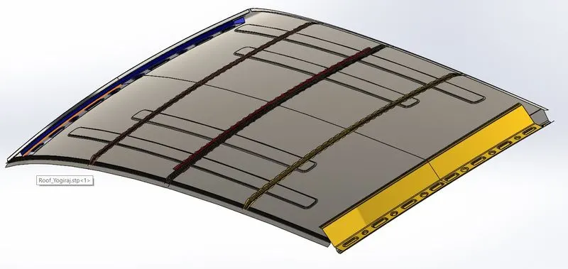
Roof challenge
Aim:
To Design the Roof of an automobile considering the necessary design requirements.
Objective:
To develop the essential flanges and reinforcements for the input Styling data using the master section. Designing of Front roof rail, Rear roof rail, Bow roofs and the central reinforcement roof.
To perform the following tests:
- Head Distortion Criteria
- Snow Load Criteria
- Draft Analysis
- Section Inertia Analysis
Introduction:
Roof:
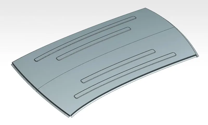
It is that component of an automobile which is placed on the top portion of the main structure of the car.
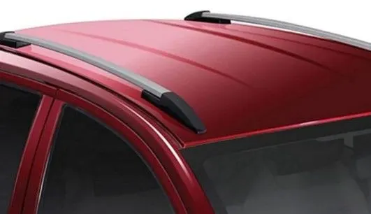
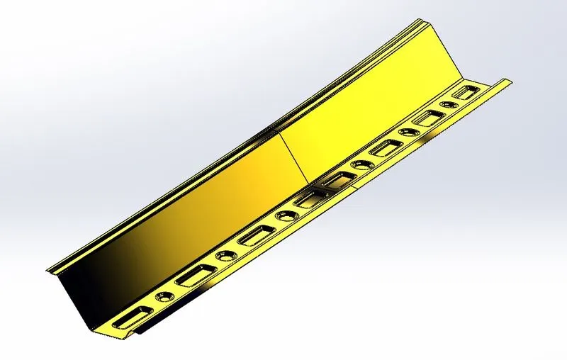
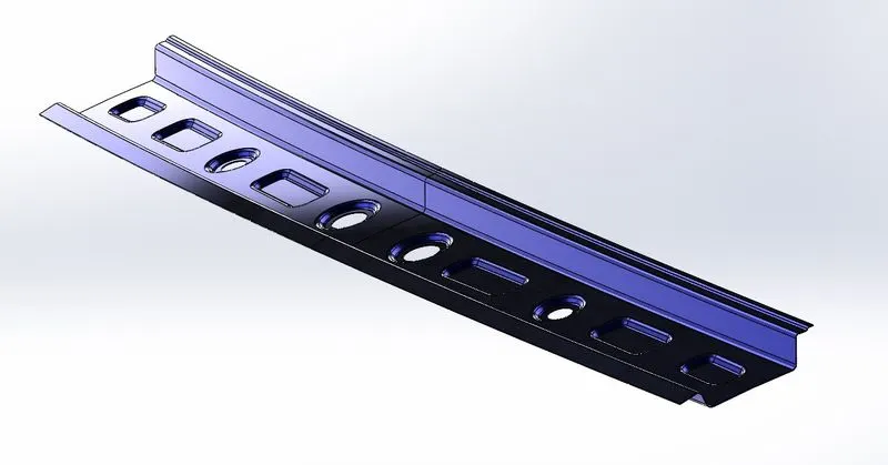
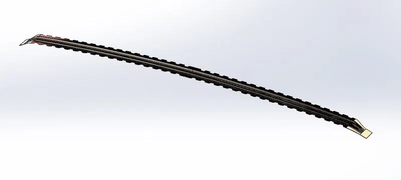
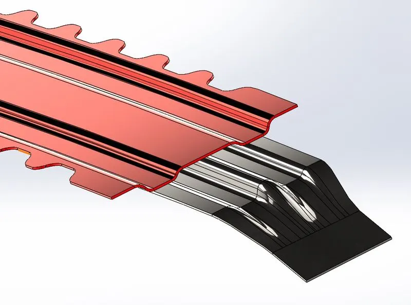
Fig:1-Automobile Roof
The main function of the roof is to protect the passengers from Sun, wind, rain, dust and other external components. The Roofs can be made up of Soft or Hard rigid material. The Soft tops are made up of Vinyl, Canvas and other textile materials. Hard top roofs are made up of Steel, Aluminium, Plastic and carbon fibre components. Roof also provides area for carrying the luggage and it improves the aesthetic look of the car from the top. The roof should be designed such that during a hazardous accident, if the car flips upside down, then the roof should be able to sustain the impact.
Design Aspect of Roof:
Rollover crash test:
The rollover crash test is performed by National Highway Traffic Safety Administration (NHTSA) essentially on SUV's, Minivans and Pickups. It is performed to optimize the roof design so that it is able to withstand the impact during a rollover. A rollover hapenens when there is a dramatic effect on the vehicle balance when the car travereses a curve which eventually shifts the Center of Gravity to one side of the vehicle.
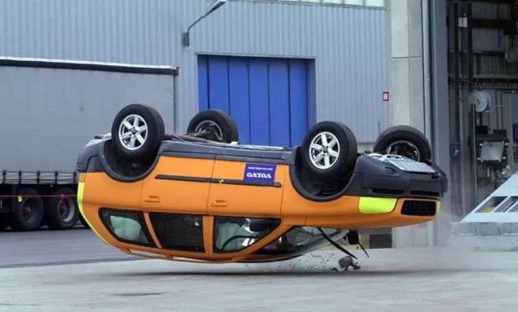
Fig:2-Rollover crash test
By performing the rollover test the car is optimized to absorb the forces and energy such that there is minimal deformation in the sitting compartment.
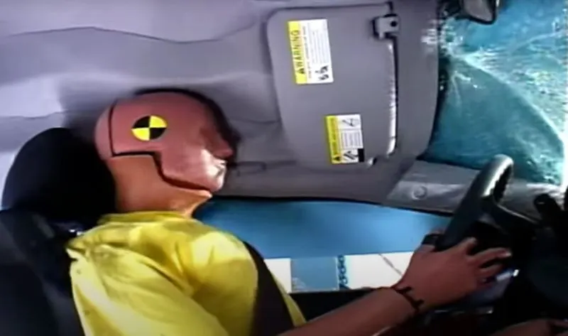
Fig:3-Minimal deformation in the sitting space
Roof Crush Test:
In this test load is applied on the roof of the car to optimize its design for a rollover crash. A load is applied for a duration of 120 ms and the protrusion of the roof is analyzed. The time taken by the roof to recover and come back to its original position is also optimized. During this test all the windows and the doors are closed. The body or the chasis is fixed on a hard and horizontal surface to replicate the automobile condition during a rollover. The load v/s displacement graph is plotted. If the displacement crosses the critical value then the thickness of the rails is increased or more mastic points are introduced.
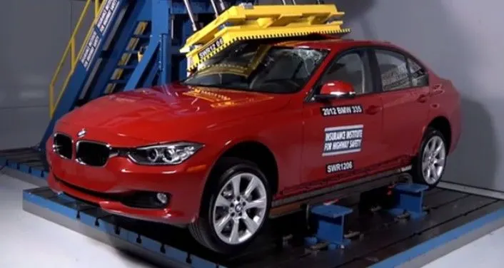
Fig:4-Roof crush test
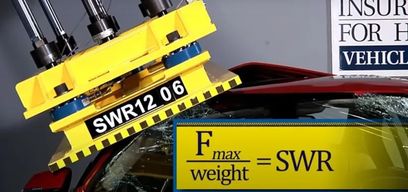
Fig:5-Strength to weight ratio
In the Roof crush test, the strength to weight ratio (SWR) should be greater than 4 according to the crash test standards.
Roof Design:
Input Data:
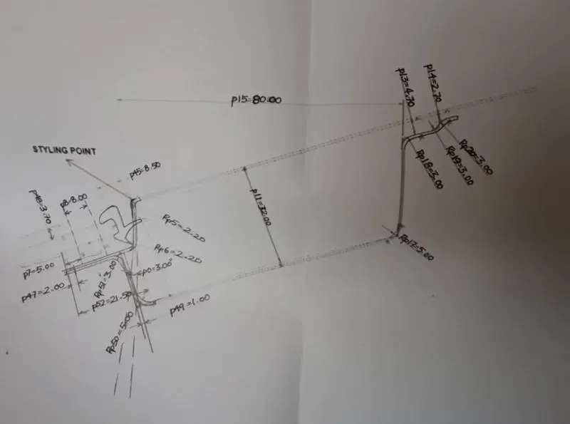
Fig:6-Master section of Front roof rail
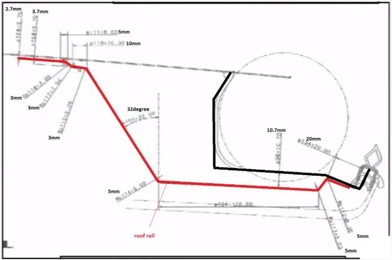
Fig:7-Master section of Rear roof rail
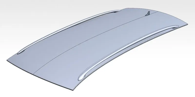
Fig:8-Roof styling skin
Roof Design in NX CAD:
1. Ditch area:
This is the key part of the roof which saves the vehicle during the rollover. It is the part to which all the reinforcements and rails are attached using the mastic sealants for improving the strength of the roof. It is designed considering the standards for headroom clearance, curvature, etc. All the necessary flanges are provided to this component for its attachment with the rails and reinforcements. This part is given a thickness of 0.75 mm inwards in NX CAD.
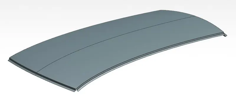
Fig:9-Development of ditch area in NX CAD
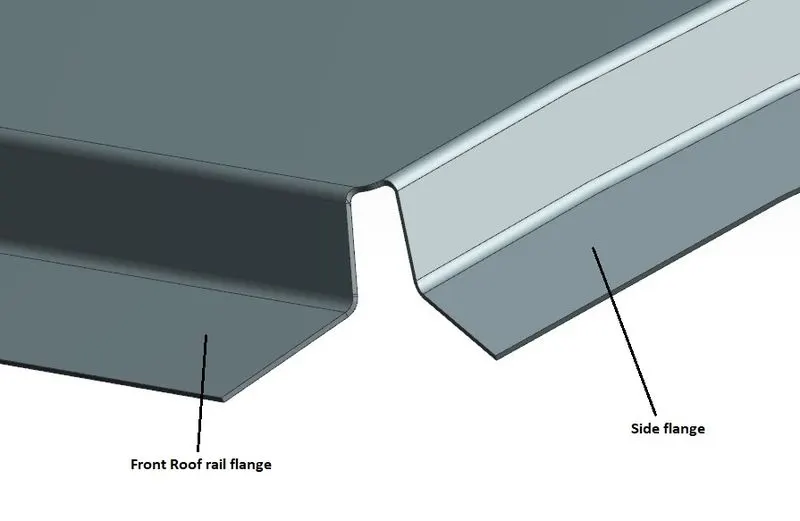
Fig:10-Flanges for front roof rail and bow roof end
The flanges are created with a minimum angle of 3 degrees so that the part can be manufactured efficiently by deep drawing. This is done so that the tool should not get stuck inside the work part. Proper angles and dimensions are required to maintain the standard for Visibility criteria.
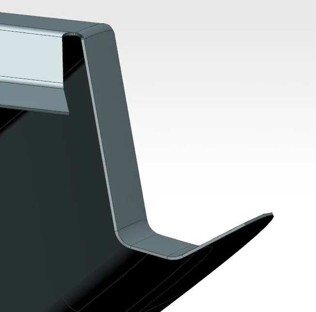
Fig:11-Rear Flange
2. Front Roof Rail:
The Front roof rail is a reinforcement material which is positioned towards the front of the roof. It is used to connect the windshield glass with the body side outer. This rail is designed based on the roof data and it should follow the Head room clearance criteria. The front roof rail should not obstruct the driver's vision nor should it should reduce the sitting area.
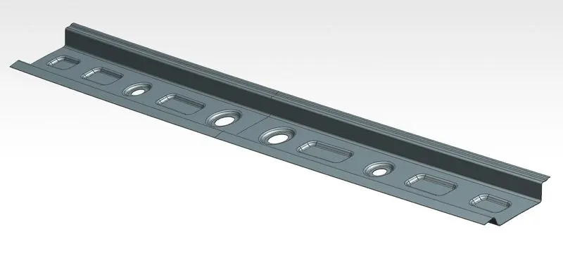
Fig:12-Front roof rail
Additional embosses are given to the rail to increase its strength.
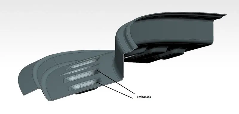
Fig:13-Embosses in Front roof rail
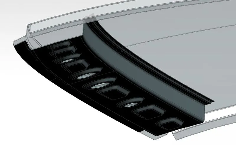
Fig:14-Positioning of Front roof rail
3. Rear Roof Rail:
The rear roof rail is another reinforcement material which is positioned at the back of the roof. It is used to join the backdoor with the body side outer. The rear roof rail is poitioned at the back to increase the strength of the rear roof side. It is modeled in such a way that the material requirement is minimum and the parts are easily deep drawn.
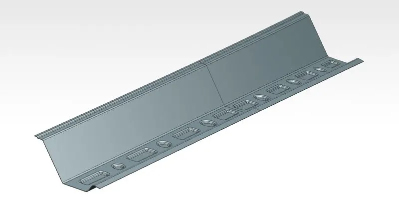
Fig:15-Rear Roof Rail
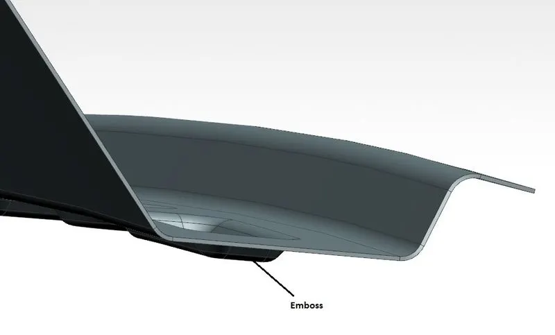
Fig:16-Embosses in rear roof rail
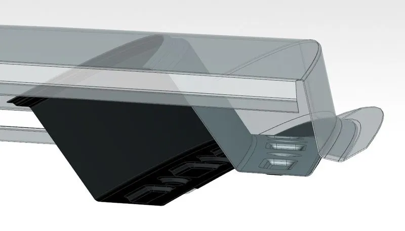
Fig:17-Positioning the rear roof rail
4. Bow roof:
These rails are placed at the areas of minimum radius of curvature inorder to increase the strength of the roof. Generally two-three bow roofs are present in the roof design to increase the strength of the roof. In my roof design I have used 3 Bow roofs namely Frontal bow roof (Bow roof 1), Mid bow roof (Bow roof 2) and rear bow roof (Bow roof 3).
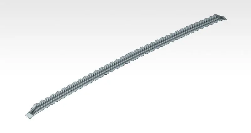
Fig:18-Frontal Bow Roof
The bow roof is designed such that it can be attached with the side flanges of the roof.
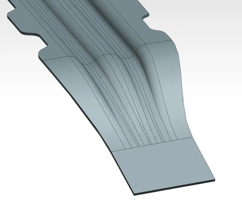
Fig:19-Bow roof end
The mastic points are created to attach the bow roof with the inner side of the roof using the mastic sealants. The mastic points are useful in reducing the Noise, Vibration and Harshness issues locally.
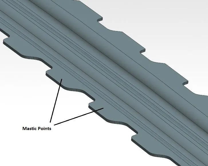
Fig:20-Mastic Points
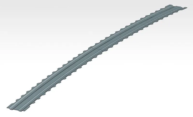
Fig:21-Mid Bow roof
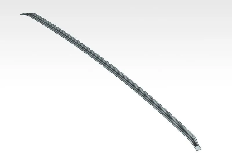
Fig:22-Rear bow roof
5. Central Reinforcement Roof Rail:
This is a reinforcement roof rail positioned below the Mid bow roof to increase the strength of the roof. This is joined using mastics with the inner roof and the mid bow roof is spot welded with the Central reinforcement roof rail.
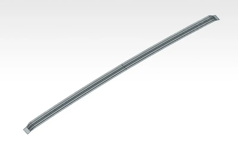
Fig:23-Central Reinforcement roof rail
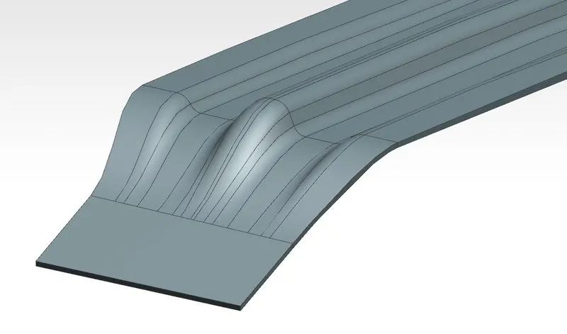
Fig:24-End part of the Central roof rail
The central roof rail is placed between the mid bow roof and the inner side side of the roof.
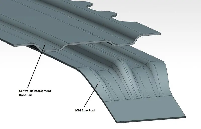
Fig:25-Central roof rail and mid bow roof
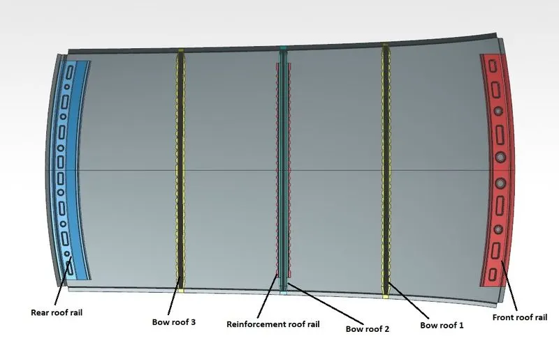
Fig:26-Layout of rails and ditch area
Heat Distortion Criteria:
It is an analysis which is used to study the curvature. This is used to justify the positioning of the bow roofs which are to be fixed to the ditch area. The formula is used to predict the effective positioning of the bow roofs.
Bow roof prediction formula:
W = [1.73 x 10^(-3) x L] + [1.85 x 10^(-8) x (R^2)/t] + [ 1.10x10^(-3) x l] - 2.68
L=Roof length in X- direction (mm) where roof dimension in 0-Y
R=2(Rx*Ry)/(Rx+Ry)
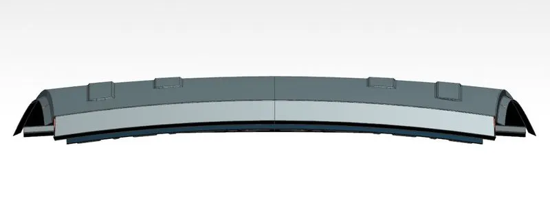
Rx=Curvature in x
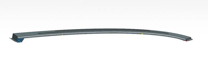
Ry=Curvature in y
t=Roof plate thickness (mm)
l=Bow Span (mm)
The positioning of the bow roof is approved if the value of W is below 2.7 mm.
A horizontal line (0Y) is drawn which connects the extreme points. This line is offsetted by 300 mm in the negative y direction. This -3Y line is again offsetted bi-directionally by 100 mm. Four vertical lines are drawn which are symmetrically placed between the rail-pairs. These 4 lines are again offsetted by 100 mm.
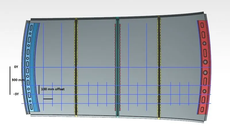
Fig:27-Sketch for Head Distortion Criteria
The 5 points formed at each pair is projected on the roof surface.
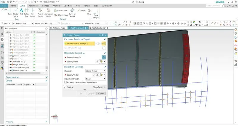
Fig:28-Projecting points on the body
Arcs are formed in X and Y direction. After creating the arc its respective radius of curvature is noted.
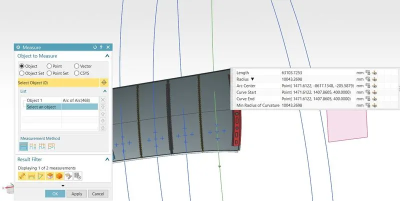
Fig:29-Radius of curvature
For the arc between front roof rail and bow roof 1, the radius of curvature in Y direction, is Ry=10043.26 mm
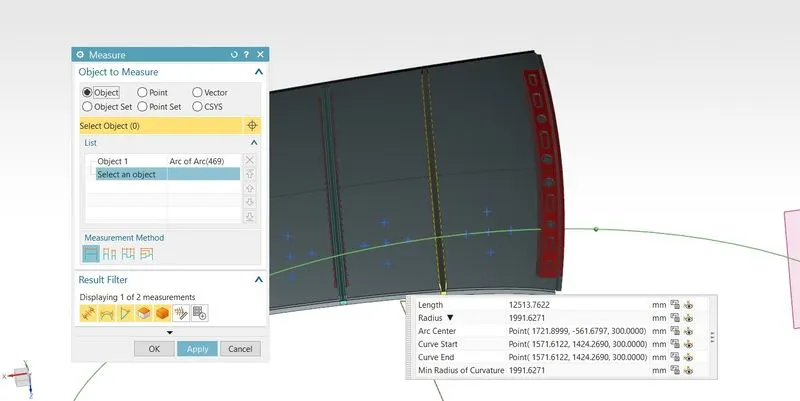
Fig:30-Radius of curvature, Rx=1991.62 mm
Similarly Rx and Ry for all the 4 locations are measured.
Bow roof span (l) is the distance between the rails in x direction
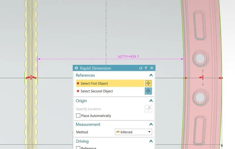
Fig:31-Bow roof span
For the first pair, l=439.1 mm, similarly the rest spans are measured.
L is the Roof length in X direction
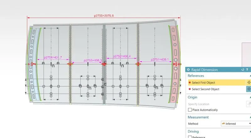
Fig:32-Roof Length, L= 2076.8 mm
t is the thickness of the roof plate.
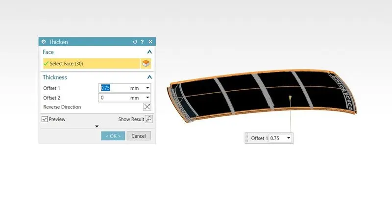
Fig:33-Roof plate thickness= 0.75 mm
By using all the values, W is calculated for each pair.
Heat Distortion Criteria Table:
| Sr. No. | Position | Rx (mm) | Ry (mm) | R (mm) | l (mm) | L (mm) | t (mm) | W | Result |
| 1 | FRR & BR1 | 1991.62 | 10043.26 | 3346.30 | 439.1 | 2076.8 | 0.75 | 1.67 | Pass |
| 2 | BR1 & BR2 | 6488.67 | 4898.76 | 5582.69 | 408.4 | 2076.8 | 0.75 | 2.13 | Pass |
| 3 | BR2 & BR3 | 10241.75 | 4043.65 | 5797.97 | 408.3 | 2076.8 | 0.75 | 2.19 | Pass |
| 4 | BR3 & RRR | 4580.90 | 4347.60 | 4461.20 | 431.7 | 2076.8 | 0.75 | 1.87 | Pass |
Note:
FRR-Front Roof rail
BR1-Bow roof 1
BR2-Bow roof 2
BR3-Bow rood 3
RRR-Rear Roof rail
Result:
For all the pairs, the value of W is less than 2.7 hence, the positions of bow roofs are justified by the Head Distortion Criteria.
Draft Analysis:
This analysis is used to check the draft angles of the part designed in the software. It should be ensured that there are no negative drafts. If there are negative drafts then the manufacturing of the part by deep drawing will not be feasible. The tool will get stuck inside the work part if the angle is negative or less.
Draft analysis of parts in NX CAD:
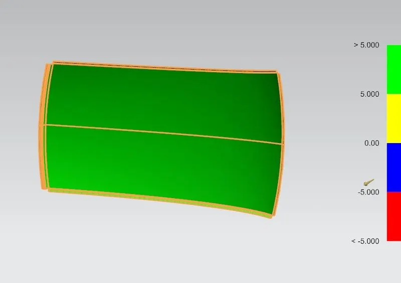
Fig:34-Ditch area
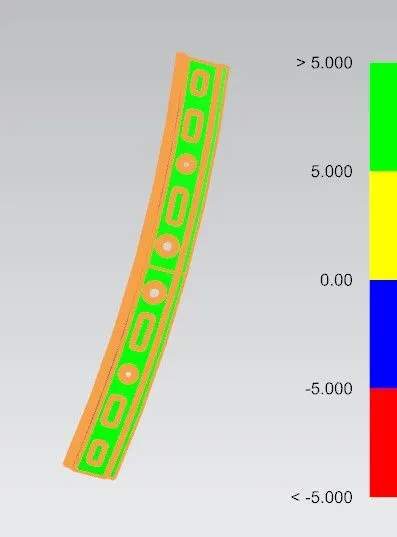
Fig:35-Rear Roof rail
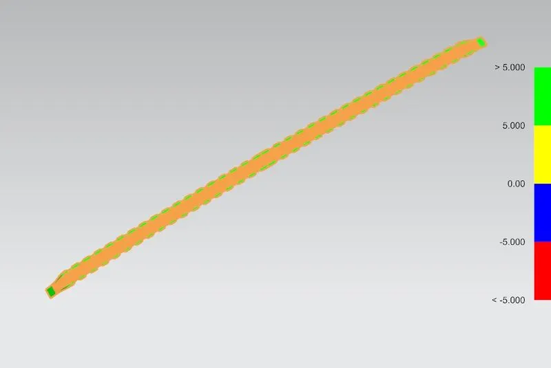
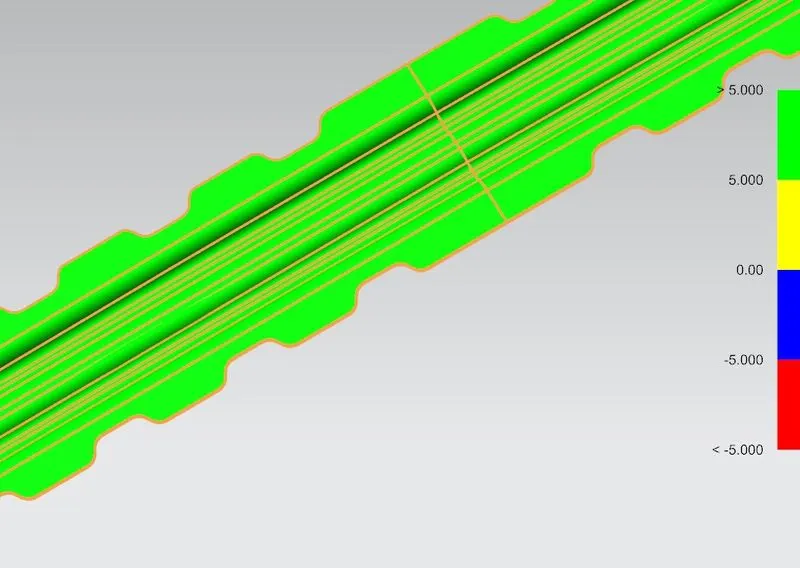
Fig:36-Bow roof 1
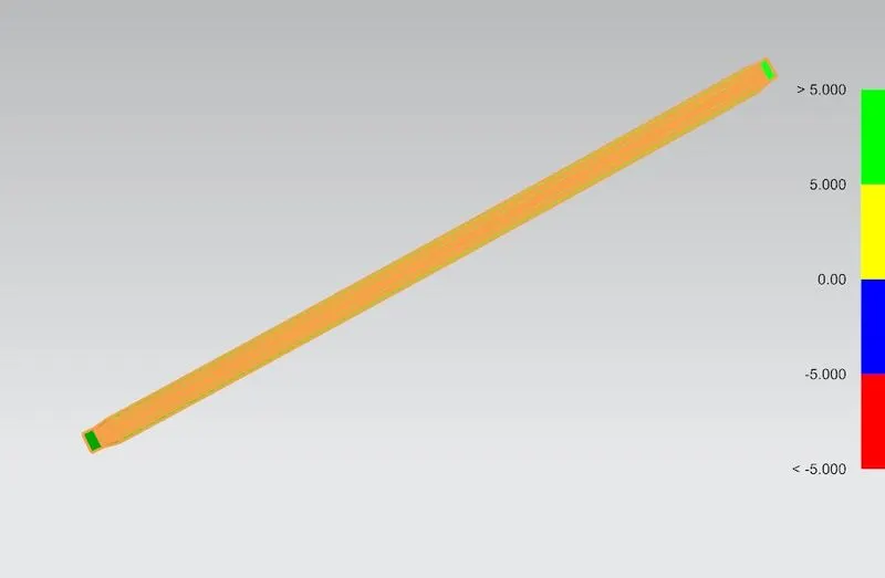
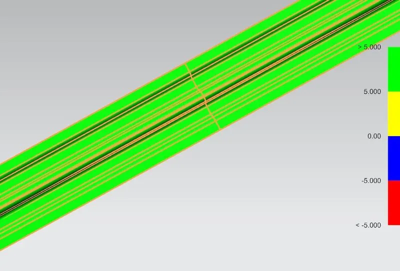
Fig:37-Bow roof 2
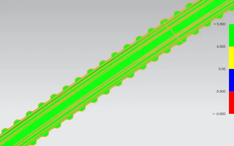
Fig:38-Reinforcement roof rail
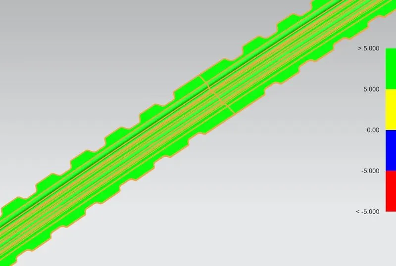
Fig:39-Bow roof 3
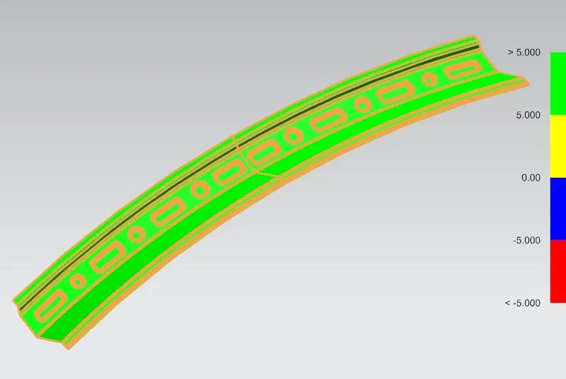
Fig:40-Rear Roof rail
Result:
For all the components the draft is greater than 5 degrees with respect to the drawing Y direction. Green colour indicates that all the components can be manufactured by deep drawing.
Section Inertia Analysis:
This analysis is used to find the moment of inertia of the section formed by the rails and the reinforcements. Section Inertia analysis tool in NX CAD finds the Principal moment of Inertia, circumference, area and center of gravity of the section sketch under consideration.
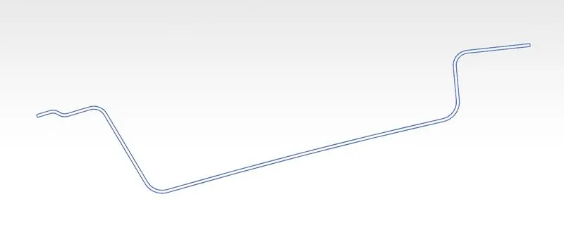
Fig:41-Section sketch of Front Roof rail
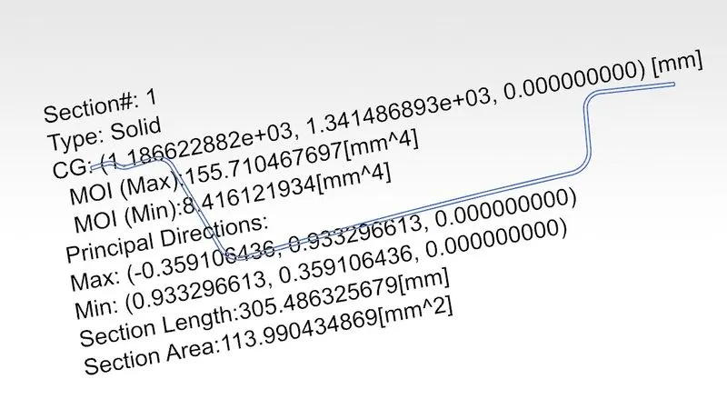
Fig:42-Minimum moment of Inertia, I=8.416 mm^4
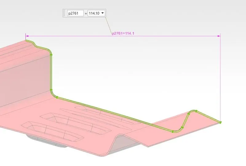
Fig:43-Section length
Section length, Y=114.1 mm
Section modulus, S=I/0.5Y=0.1475 mm^3
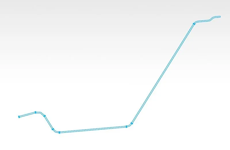
Fig:44-Section sketch of Rear Roof rail
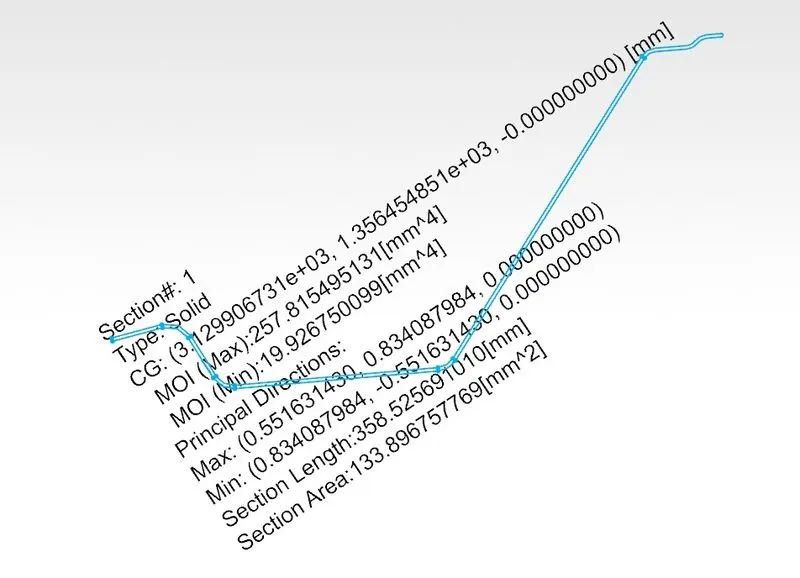
Fig:45-Minimum moment of Inertia, I=19.926 mm^4
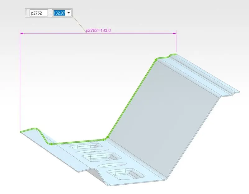
Fig:46-Section length
Section length, Y=133.0 mm
Section modulus, S=I/0.5Y=0.299 mm^3
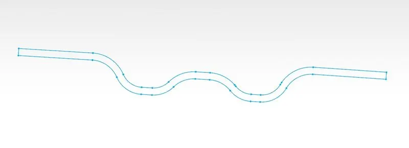
Fig:47-Section sketch of Bow roof 1
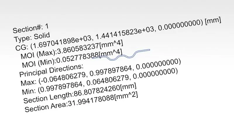
Fig:48-Minimum moment of Inertia, I=0.052 mm^4 (Used for 1st pair of Snow load criteria)
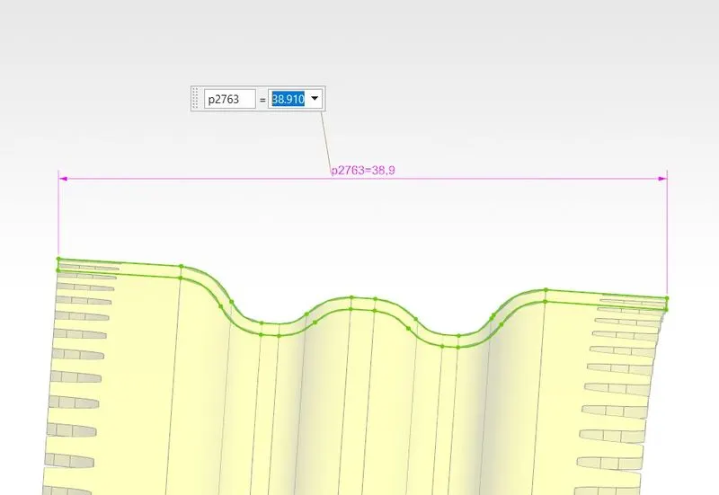
Fig:49-Section length
Section length, Y=38.9 mm
Section modulus, S=I/0.5Y=0.0026 mm^3
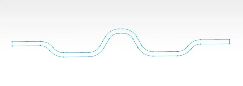
Fig:50-Section sketch of Bow roof 2
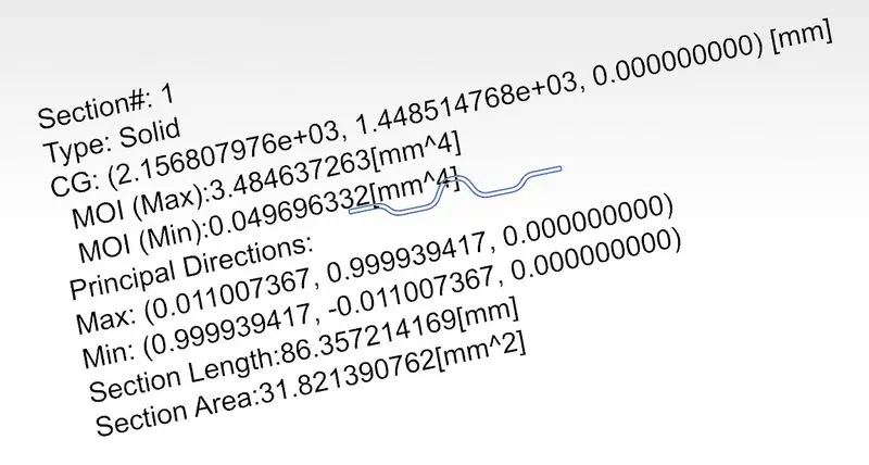
Fig:51-Minimum moment of Inertia, I=0.049 mm^4
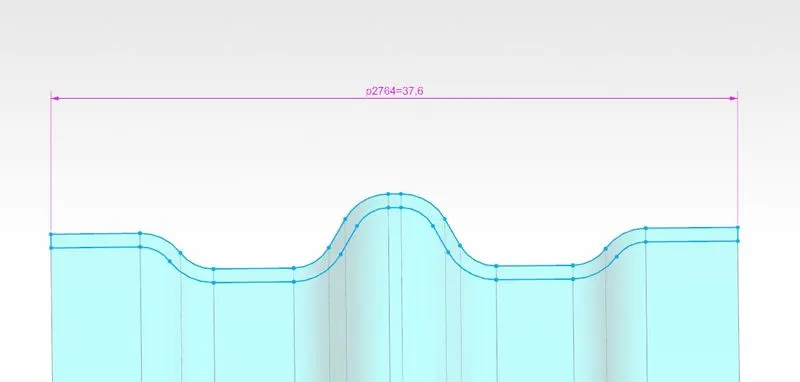
Fig:52-Section length
Section length, Y=37.6 mm
Section modulus, S=I/0.5Y=0.0026 mm^3
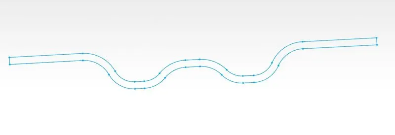
Fig:53-Section sketch of Bow roof 3
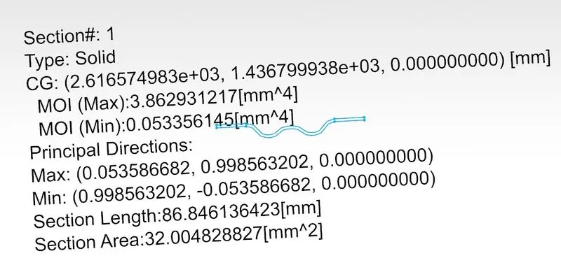
Fig:54-Minimum moment of Inertia, I=0.053 mm^4 (Used for 3rd pair of SNC)
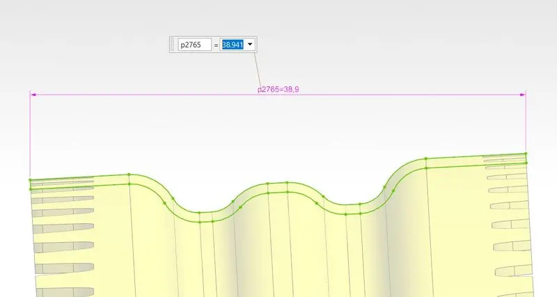
Fig:55-Section length
Section length, Y=38.9 mm
Section modulus, S=I/0.5Y=0.0027 mm^3
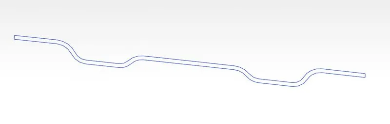
Fig:56-Section sketch of reinforcement roof rail
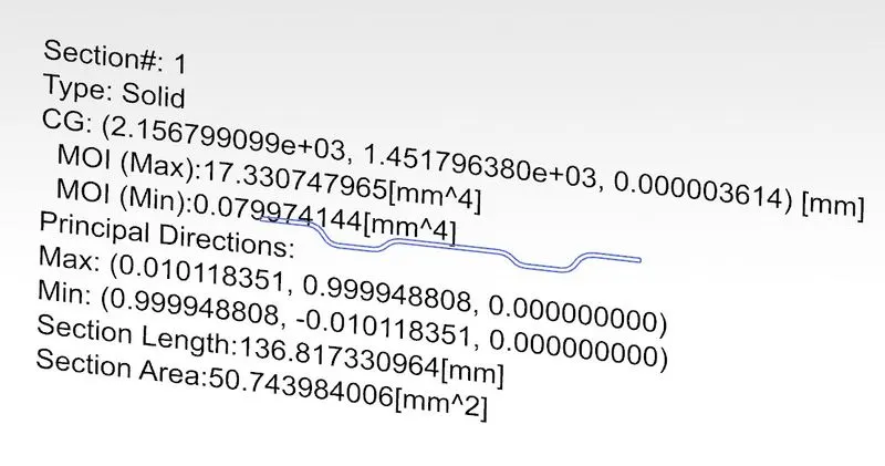
Fig:57-Minimum moment of Inertia, I=0.079 mm^4
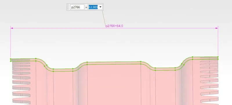
Fig:58-Section length
Section length, Y=64 mm
Section modulus, S=I/0.5Y=0.0012 mm^3
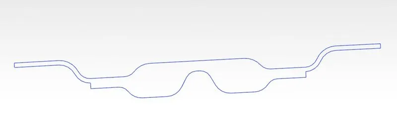
Fig:59-Combined section sketch of reinforcement roof and bow roof 2
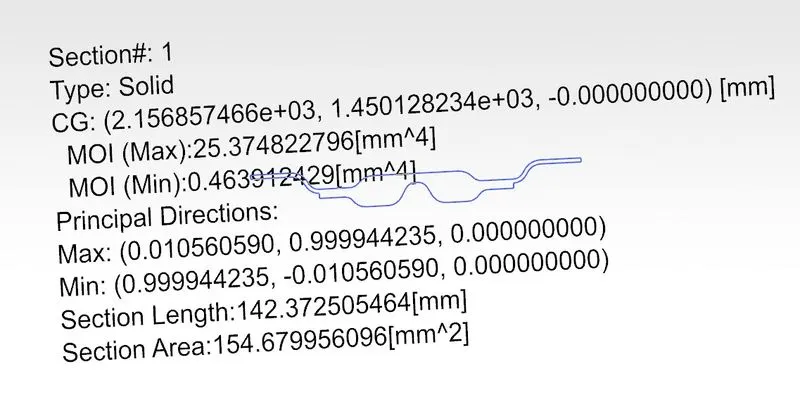
Fig:60-Minimum moment of Inertia, I=0.463 mm^4 (Used for second pair of SNC)
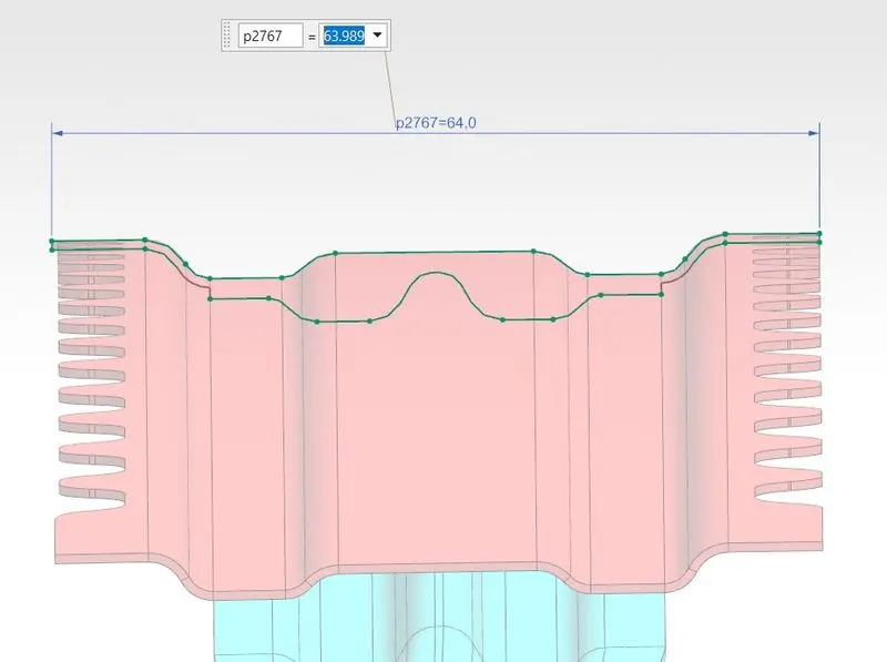
Fig:61-Section length
Section length, Y=64 mm
Section modulus, S=I/0.5Y=0.0072 mm^3
Result:
The section modulus is a measure of strength of the component. The strength of all the roof rails was computed.
Snow Load Criteria:
This analysis is used to ensure that the roof does not exhibit permanent deformation under a distributed load or snowed load. It uses Radius of curvature and minimum moment of inertia of the sections for finding Qr. If the value of Qr is less than 3.1 then the roof is likely to undergo a permanent deformation. The design is optimized such that Qr is always greater than 3.1.
Snow Load Prediction Formula:
Qr = [Iy x t2] / [α x s x [(Rx + Ry)/2]2 x 10-8]
α = My x Lx2 x 10-12 , My = Y(Ly-Y)
Judgement condition:
Qr ≥ 3.1
250 ≤ s ≤ 380
t = Roof plate thickness (mm)
Ly = Total length of the roof in Y direction
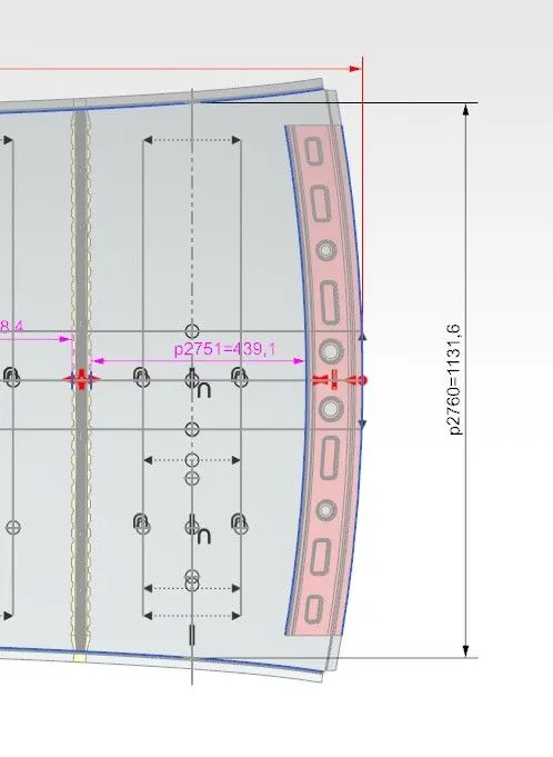
Lx = Distance between left and right points measured vertically
Y = Distance between rail centers
s = Distance for which Roof BOW bears divided load (mm)
s = L1/2 + L2/2
Iy = Geometrical moment of inertia of Roof BOW (Y cross-section )(mm4)
Rx = Radius of curvature measured in X direction
Ry = Radius of curvature measured in Y direction
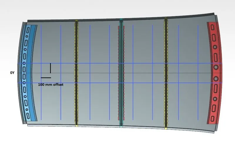
Fig:62-Sketch for snow load criteria
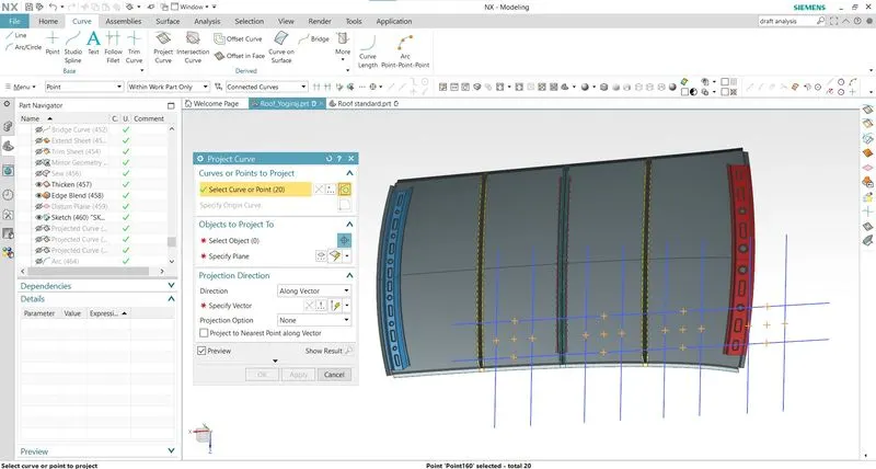
Fig:63-Projecting the points on the body
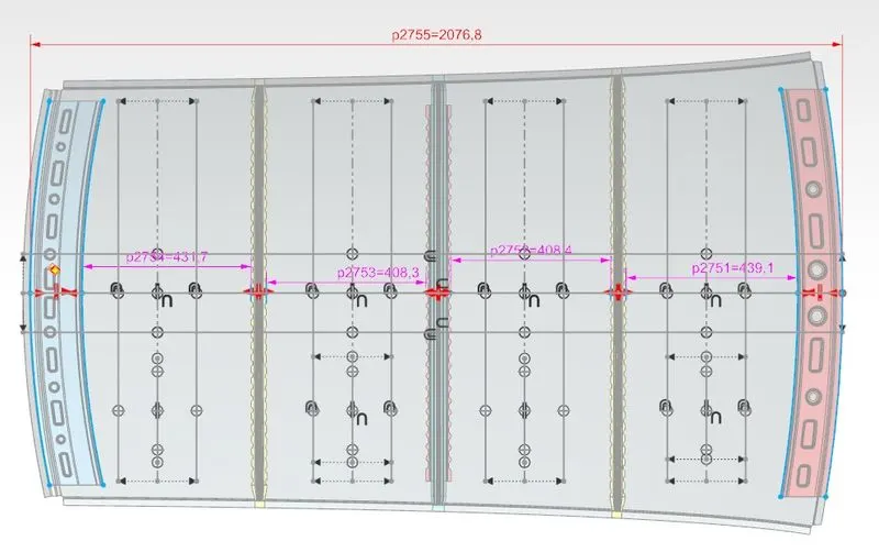
Fig:64-Roof length, Ly=2076.8 mm
Calculation of s:
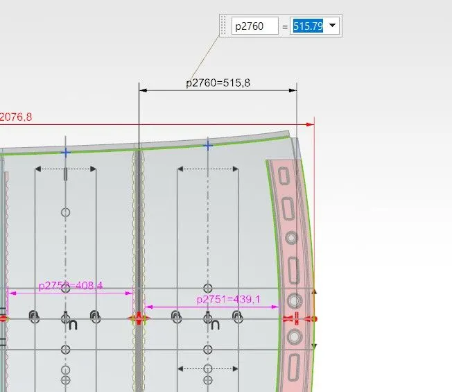
Fig:65-Y for pair 1= 515.79 mm
L1 and L2 for all 3 pairs: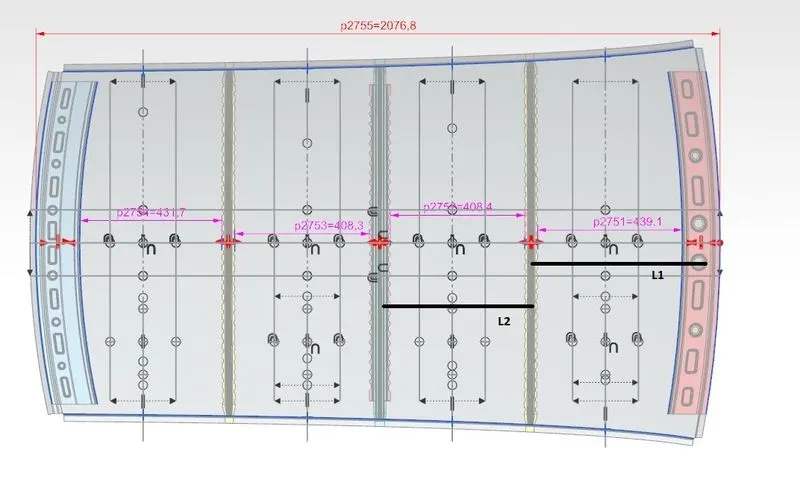
Fig:66-For pair 1
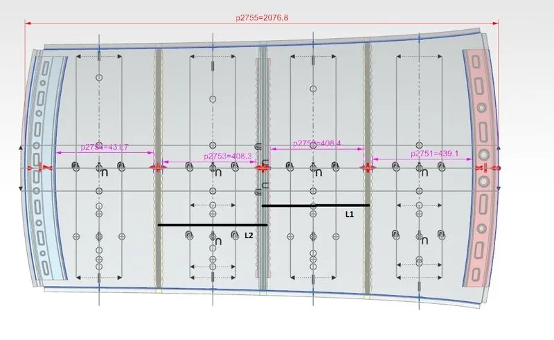
Fig:67-For pair 2
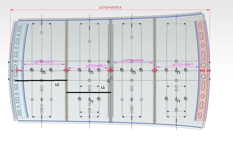
Fig:68-For pair 3
Table for s:
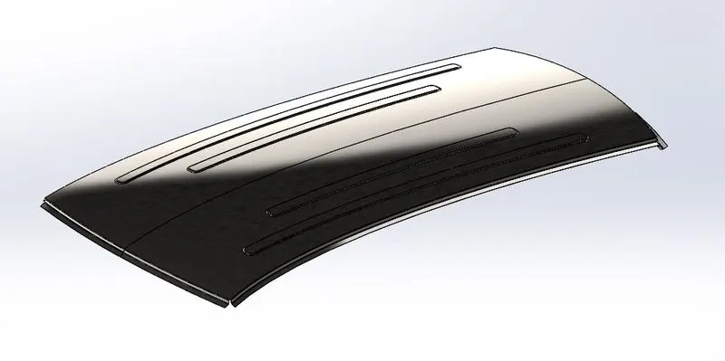
The value of s should lie between : 250>or=s Since the value of s is not under the standard range, the positioning of the bow roofs can be altered. Fig:69-Lx for pair 1 = 439.1 Similarly Lx at each point is measured. Table for SNC: Result: The design does not pass the Snow load criteria hence the positioning of bow roofs should be altered and the thickness can be increased. Embosses on roof: Additional Embosses are provided to increase the strength of the ditch area. Fig:70-Embosses on roof Roof design in NX CAD: Fig:71-Front view Fig:72-Side view Roof in SolidWorks: The file is exported as STEP. Fig:73-Ditch area Fig:74-Rear roof rail Fig:75-Front roof rail Fig:76-Bow roof Fig:77-Bow roof and reinforcement roof rail Fig:78-Final assembly (Inner view) Conclusion: The roof of the automobile was designed in NX CAD and various tests were performed to determine the efficacy of the design.
Sr. No.
L1 (mm)
L2 (mm)
s (mm)
Result
1
515.8
459.8
487.4
Fail
2
459.8
459.8
459.8
Fail
3
459.8
517.7
488.7
Fail
Sr. no.
Position
Rx (mm)
Ry (mm)
R (mm)
Lx (mm)
Ly (mm)
Y (mm)
Iy (mm^4)
My (mm^2)
1
FRR & BR1
2850.50
4367.84
3609.17
1131.6
2076.8
515.8
0.052
805163.8
2
BR1 & BR2
6409.45
5276.22
5842.83
1084.3
2076.8
459.8
0.463
743496.6
3
BR2 & BR3
10667.17
6222.24
8444.70
1059.9
2076.8
459.8
0.053
743496.6
4
BR3 & RRR
16368.69
4009.93
10189.31
1044.1
2076.8
517.7
-
-
t (mm)
α
Qr
Result
0.75
1.031
4.464*10^-4
Fail
0.75
0.874
1.890*10^-3
Fail
0.75
0.835
1.024*10^-4
Fail
0.75
-
-
-