Hood design-Week 2
Aim:
To Design and Assemble the Hood and all its components considering the Design Standards.
Objective:
The main Objective of this Project is to Design the Hood or Bonet Components which include the Outer Panel, Inner Panel and the Reinforcements by following the master section and using the skin data. After desigining the components they have to be properly assembled using the Latch Trajectory. To perform Draft analysis and Section Modulus Analysis.
Introduction:
Hood:
The Hood is that Part of an Automobile which acts as a Cover which is hinged at the front portion of a Front-Engine Car. It functions as a door which covers the Engine Compartment.
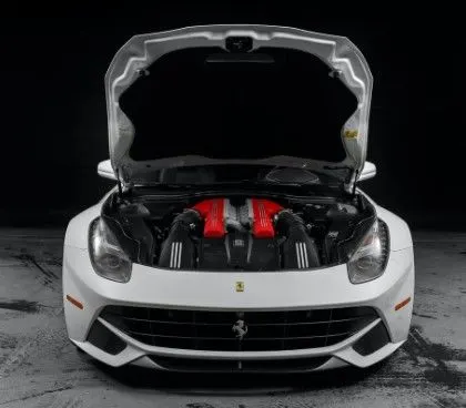
Fig:1-Hood Image
Hood Design Criteria:
1) Hood Opening Angle:
The extent to which the Hood or the Bonnet will open is standardized according to the region. The average heights of people are different in different countries and this height standard is used in determining the opening angle of the Hood.
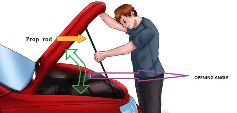
Fig:2-Hood Opening Angle
The Average Height of Indian Men is 5ft 5 inch and the opening angle is close to 60 Degrees. However, in Netherlands the average height is 6ft 1/2 inch and the opening angle is close to 80 Degrees.
The Opening Angle can be changed by predefining the length of the Support rod or Gas Stay.
Hood Stay:
A Hood Stay is an apparatus for an Engine room of a car, which can safely keep an Engine hood in an open state even if an external force is abruptly generated due to vibratiom, wind and can facilitate opening/closing operation of the Engine Hood. There are two types of Hood stay, namely, Gas Stay and Support Rod.
A) Gas Stay:
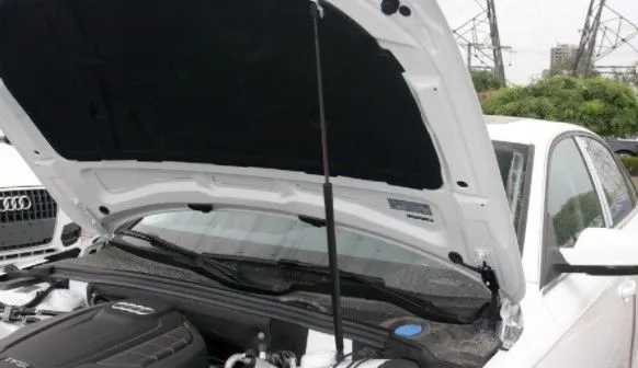
Fig:3-Gas Stay
The Gas Stay is a device which is used to keep the hood in an open position by means of an actuator which is activated by the gas. In this device no man power is required and it is more convenient. The weight of the Gas stay is more than the support rod hence, additional reinforcements or brackets are provided to increase the strength locally.
B) Support Rod:
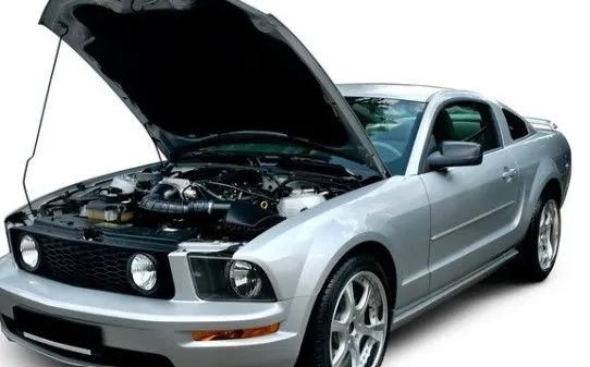
Fig:4-Support Rod
The Support Rod is a Rod which is used to keep the Hood of the car in open position. It can be hinged on the Engine compartment and held by the Hood or it can be hinged at the Hood and can be mounted on the Engine Compartment. This is simple and cost effective but human effort is required which is more than that in Gas Stay use. The support rod is purposely bent inorder to increase its stiffness and to prevent wobbling. Length from the line conncecting support rod retaining point with retaining point on the Body side to maximum bending point cannot be more than 35mm to ensure the strength of the rod.
2) Pedastrian Safety:
A pedestrian can be defined as a vulnerable road user that is at risk when it comes to roads. Thus the safety of such being is essential. The pedestrian safety and protection norms are aimed to do so. It will ensure that the new cars meet a minimum requirement of safety for the pedestrians. It’s one of the phases of Bharat New Safety Vehicle Assessment Program (BNVSAP). The major reasons for pedastrian accident are distracted driving, speeding, intoxicated driving, poor reaction time and reverse parking.
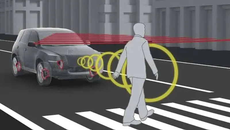
Fig:5-Pedastrian Safety
Pedastrian safety tests:
Globally various NCAPs (New Car Assessment Programme) are present that performs the pedastrian safety tests on new vehicles and rate them accordingly. The Euro NCAP has five parameters for pedastrian safety test for new vehicles.
1. Head Impact:
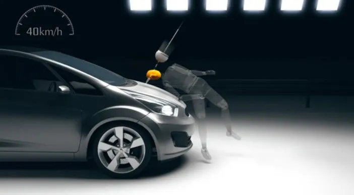
Fig:6-Head Impact (Euro NCAP)
The Head Impact test is carried out for a vehicle speed of 40 km/h. It gives an estimate of the potential head injury in the fateful event of a vehicle striking an adult or a child, a head form impactor is used in a series of impact tests and the impact sites are then assessed for and rated accordingly. This test will give essential information about the deformation clearance, energy-absorbing structures and deployable protection systems such as pop-up bonnets and external airbags in a new vehicle.
2. Upper Leg Impact:
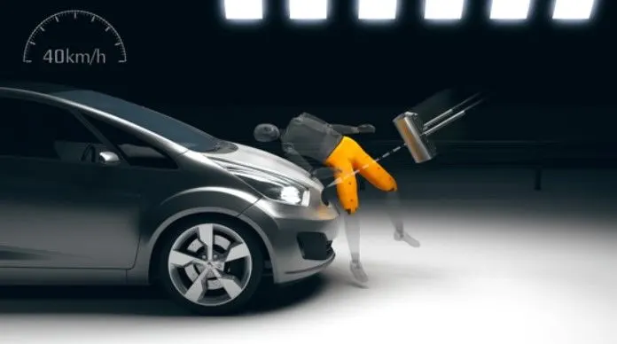
Fig:7-Upper leg impact (Euro NCAP)
The facility carries out the test at the vehicle speed of 40 km/h. An adult upper leg form impactor is used in a series of impact tests and then the impact sites are assessed. The protection is then rated as good, adequate, marginal, weak or poor. The test procedure allows to check the energy-absorbing capacity of the structures of a vehicle and also check whether the geometry of the vehicle allows mitigation of injuries.
3. Lower Leg Impact:
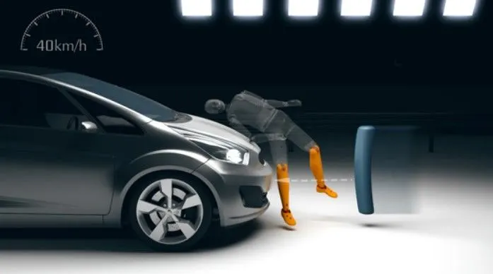
Fig:8-Lower leg impact (Euro NCAP)
Euro NCAP carries the test at the same speed standard as the above ones. It uses an adult leg impactor and a series of tests are carried out. Impact sites are then assessed and the protection rating is offered.
4. AEB Pedastrian:
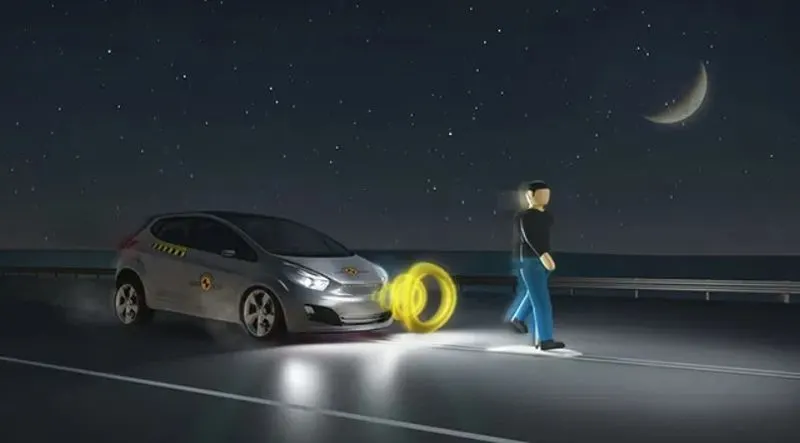
Fig:9-AEB Pedastrian (Euro NCAP)
AEB stands for Autonomous Emergency Braking. For this test, the NCAP uses a specially-designed pedestrian form which has articulated limbs to replicate the walking motion of a human. Cars are assessed on the basis of how forgiving the front-end design is in case of impact. AEB pedestrian tech may not be able to completely avoid a collision in some cases. The tests are done in the day as well as night to ensure vulnerable road users are protected all the time.
5. AEB Cyclist:
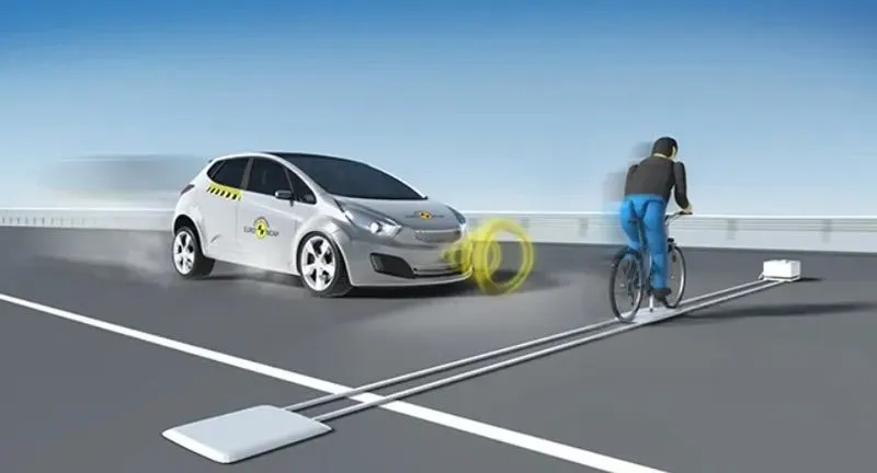
Fig:10-AEB Cyclist (Euro NCAP)
For this test, Euro NCAP uses a specially designed cyclist form which will replicate the actual cyclist on the road. Euro NCAP offers the highest rating if the collision is completely avoided. The vehicle is also awarded if the speed is reduced as any reduction in speed of impact can significantly reduce the injury to the vulnerable user.
Head Impact Criteria:
The Euro NCAP Safety Assessment Program includes a test protocol for pedastrian protection. The protocol covers lower leg, upper leg and head impact tests as shown in Fig.11.
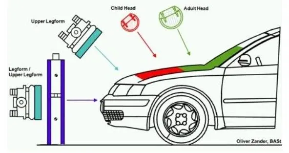
Fig:11 Impact Positions
Wrap Around Distance
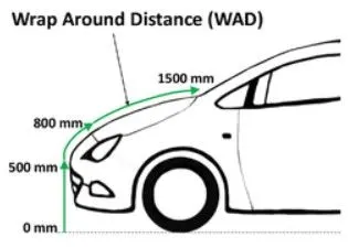
Fig:12-Wrap Around Distance
WAD (Wrap-Around Distance) means the distance from the ground to the point on the hood along the vehicle front structure.
Test Area:
The test area should be the area surrounded by the front test line, rear test line and side test lines.
Front test line:
The rear side line was chosen out of two lines to be assigned to the front test line. One line was the line
where WAD was 1,000mm. The other line was located 165mm backward from the Bonnet Leading Edge
Reference line.
Rear test line:
The front side line was chosen out of two lines to be assigned to the rear test line. One line was the line
where WAD was 2,100mm. The other line was located 82.5mm forward from the line where the impactor
contacted the bonnet when the impactor contacted both the windscreen and bonnet, assuming that both
the wiper arms and other equipment are removed.
Side test line:
The lines are located 82.5mm inside from the Bonnet Side Reference line.
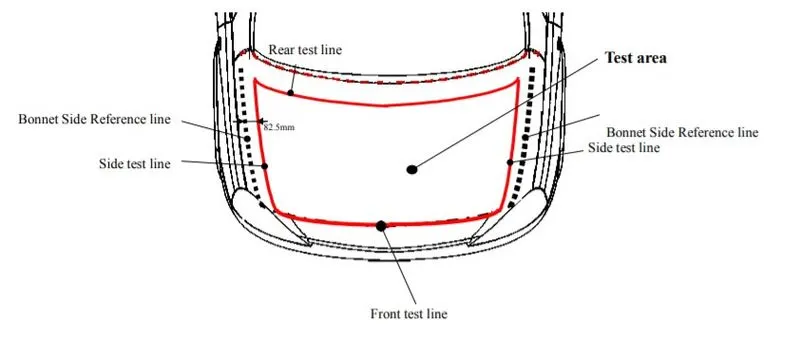
Fig:13-Test Area
Ground Reference Plane:
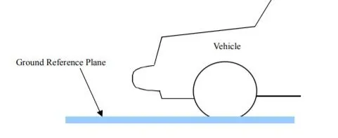
Fig:14-Ground Reference Plane
A horizontal plane that passes through all tire contact points of a vehicle while the vehicle is in its normal ride state.
Bonnet Side Reference Line:
The geometric trace of the highest points of contact between a straight edge, held parallel to the lateral vertical plane of the vehicle and inclined 45 deg. is traversed down the side of the front structure, and the
side of the front structure.
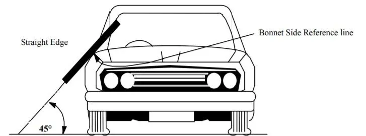
Fig:15-Bonnet Side reference
In that test protocol, semi-spherical headforms are used (3.5 kg for the child headform and 4.5 kg for the adult headform). The headforms are launched such that the angle at impact is 50° ± 2° (child headform) and 65° ± 2° (adult headform), at a velocity of 11.1 ± 0.2 m/s (which corresponds to an accident with a vehicle speed of 40 km/h). The measurements from the accelerometers mounted in the headforms are processed to calculate the corresponding HIC values, which are used in the evaluation/assessment according to the test protocol. The HIC is defined as
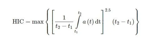
which corresponds to the maximum average acceleration value over time duration t2−t1">t2−t1, during the impact event.
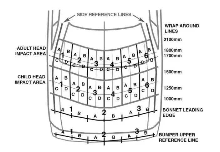
Fig:16-Impact and Distribution area
Inorder to prevent severe head injuries, the head impact area for adults and children is subjected to less thickness. The reinforcement and the projections in these areas are also reduced.
3) Noise Vibration Harshness (NVH):
Noise, Vibration and Harshness also known as noise and vibration, is the study and modification of the noise and vibration characteristics of vehicles, particularly cars and trucks. NVH testing and NVH analysis solutions are ideal for optimizing noise and vibration of the vehicles, such as reduction, design, and quality assurance of the interior and exterior noise.

Fig:17 NVH Testing Illustration
Noise:
Noise is unwanted sound or unwanted disturbance in an electronic signal. Acoustic noise is energy transmitted to the air that causes an audible disturbance. Tools such as acoustic intensity mapping and combustion/mechanical noise separation can be used to identify the best method of noise reduction.
Vibration:
Vibration is an oscillation that causes noise and disturbance. Vibration is generally of concern due to the physical effects which can cause disturbance to people, disruption in electrical systems, and failure or breakdown in mechanical systems. Shakers and controllers are techniques used to test vibration issues.
Harshness:
Harshness is generally used to describe the severity and discomfort associated with both vibration and noise. It is a qualitative system based on desired characteristics rather than on quantifiable measurements.
NVH issues are caused by the mechanical and electrical systems of the car. The interaction of the car with the road surfaces and its passage through the air also contributes towards NVH. The main NVH sources are engine, drivetrain and tyres. Tyres are the main source of noice because of the vibrations created by their rotation.
Reducing NVH:
- Engine, exhaust and suspension noise components are mounted on rubber bushes rather than creating a metal to metal contact. The softer components acts as dampers and reduces the noise.
- To isolate the main structure of the car from the source.
- Using steering dampers to absorb shocks.
Design Methodology:
There are currently two main design methodologies employed for the protection of pedestrians in impacts against car hoods. They can be categorized as “passive” and “active” designs. In an active hood design, the Head Injury Criterion (HIC) requirements are met by designing the hood assembly with added countermeasures to reduce the impact accelerations. Example, a pedestrian airbag which deploys over the stiff A-pillar and over the lower part of the windshield.
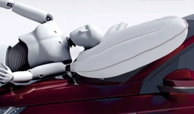
Fig:18-Pedastrian Airbag
In a passive hood design, the HIC requirements are met by designing the hood assembly such that structural compliance reduces the peak accelerations during impact. The structural requirements to achieve increased pedestrian impact protection increase the complexity of the automotive hood design process considerably. The challenge is that the structural stiffness of the hood design needs to be balanced such that during impact, the structural response is neither too stiff, nor too flexible (as contact with rigid components under the hood must be avoided). The dynamic impact targets combined with conventional structural stiffness requirements and the objective of lightweight design pose an interesting challenge in the design of vehicle hood structures. This challenge led to various studies on innovative hood designs and multi-material solutions also including fiber-reinforced composites.
Hood Design:
Input Data:
Hood Thickness Information:
Inner Panel Thickness = 0.75mm
Outer Panel Thickness = 0.75mm
Reinforcement Thickness = 1.5mm
Master Sketch:
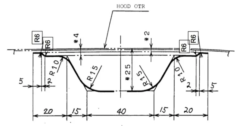
In the middle region of 40mm the Engine will be mounted. The protruding size is then reduced at the extremities to account for the housings and other mountings. The angle is kept 45 degrees because the part will be deep drawn. For the stamping process if negative draft is provided then stamping will be interrupted as the form tool will not come out.
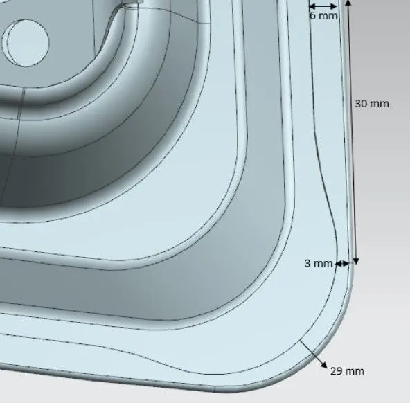
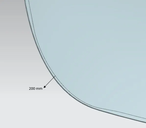
Hemming Data:
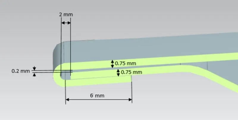
Rear Relief:
Front Relief:
Hood components Designed in NX CAD:
1. Inner Panel:
The Inner Panel is the part of the hood which exists between the Hood Outer Panel and the Engine Compartment.
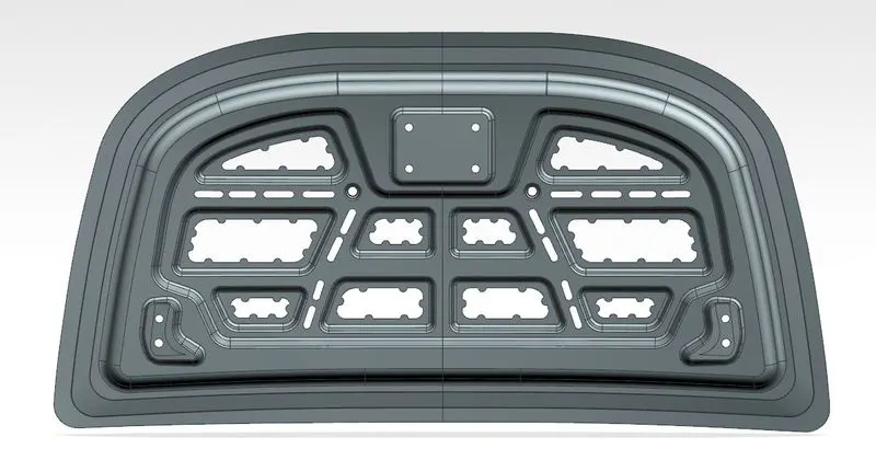
Fig:19-Inner Panel Front View
Energy Dissipation:
Considering the Safety Standards and the Head Impact Criteria the Inner Panel is provided with embosses and cutouts. The embosses helps in improving the strength of the Inner Panel. The Embosses and the cutouts are oriented in such a way that the energy is dissipated outwards. After the impact between the Pedastrian and the Inner panel, the person colliding should experience the least force and this will reduce the chances of head injury. Also the force which gets inside the cabin reduces gradually and it is a safety feature for the driver and the passengers.
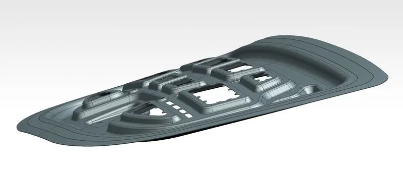
Fig:20-Embosses in Inner Panel
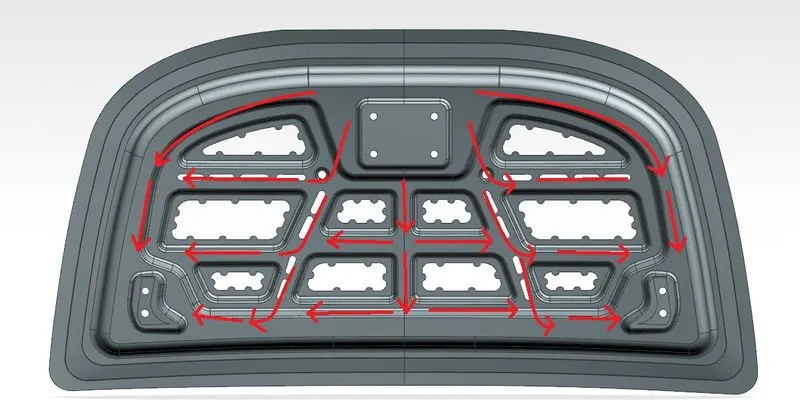
Fig:21-Energy Dissipation in Inner Panel
Mastic Points:
Mastic Points are the Circular regions provided in the inner pannel. These points are used to join the Inner Panel and the Outer Panel by using Mastic Sealant. Initially the Mastic sealant is in the form of a paste and it hardens after a Hot Furnace Bath. The Mastic Sealant has the ability to increase the strength of the Hood locally in the Diameter of 80mm. The mastics are positioned such that most of the region of the Hood is effectively covered. This is an important criteria to reduce the Noise, Vibration and Harshness issues.
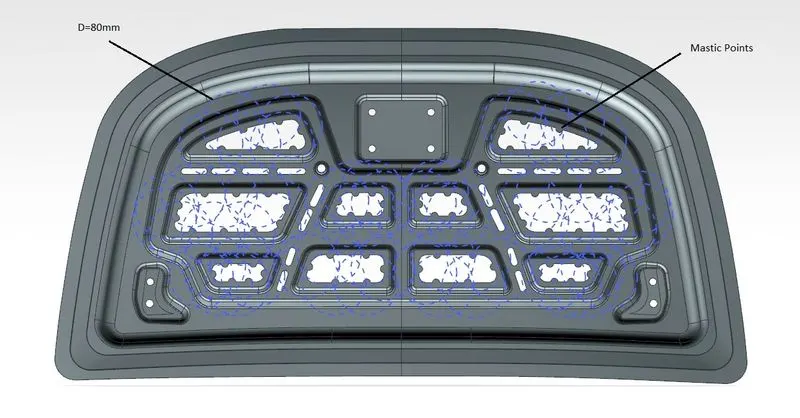
Fig:22-Mastic points in the Inner Panel
Clearance between Outer and Inner Panel:
The Distance between the mastic points and the Outer Panel should be kept less than 5mm. This is done to ensure proper application of the paste and joining of the two panels.
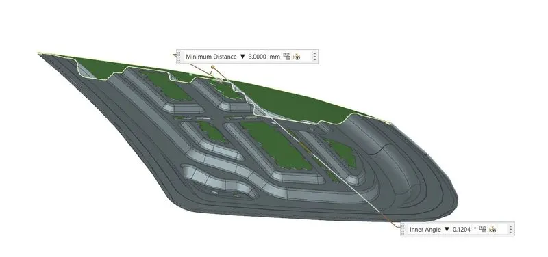
Fig:23-Section View of Outer-Inner Panel Assembly
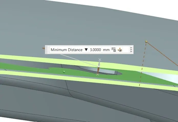
Fig:24-Distance kept = 3mm
Latch Trajectory:
It is the Circle which specifies the path of the opening and the closing of the hood. First, the Hinges are placed at the lower extreme ends of the inner pannel after mirroring the hinge assembly. An axis, connects the hinge axis of the two hinges. This axis should be kept parallel to the X-axis of the assembly for proper placement of the hinges and opening/closing mechanism.
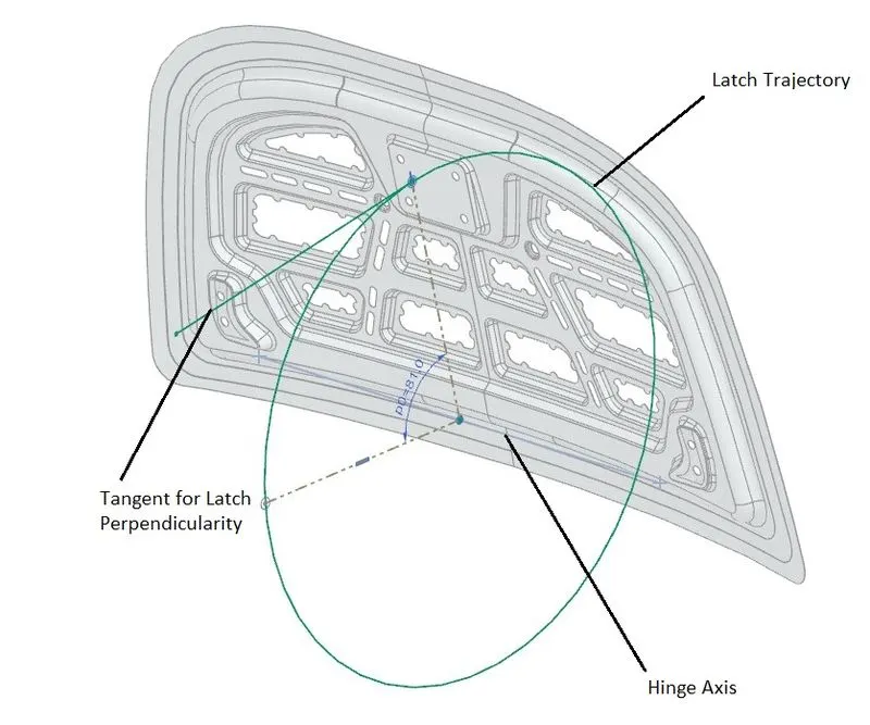
Fig:25-Latch Trajectory
After Placing the hinges, Embosses are created to fix the hinges on the Inner Panel
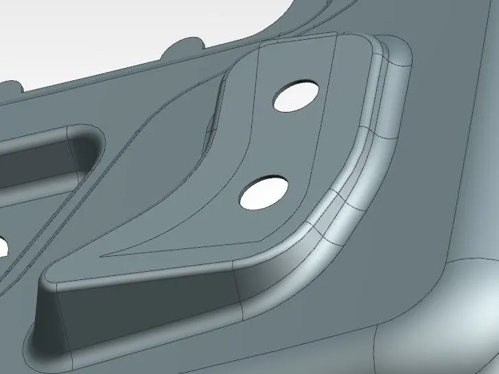
Fig:26-Hinge Embosses
Now a Tangent is constructed such that the striker is placed in the middle plane and the Latch always maintains perpendicularity.
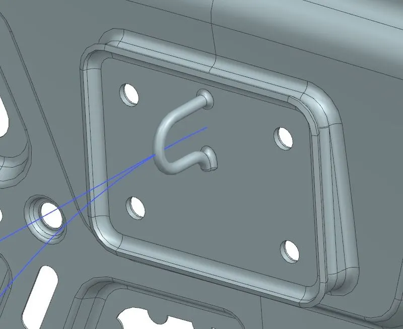
Fig:27-Perpendicularity condition
After Placing the Striker, Embosses are created to fix the Striker to the Inner Panel.
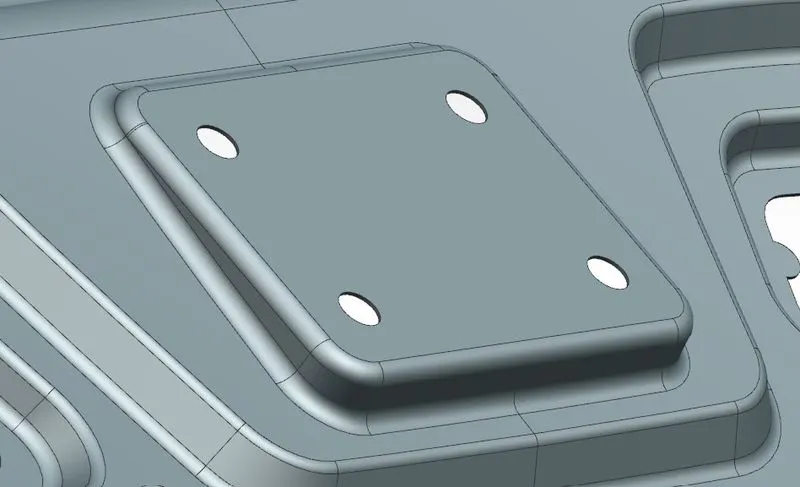
Fig:28-Emboss for Striker
Hinge and Striker Reinforcement:
After adding the Hinges and Striker to the Hood Assembly, the strength of the Hood is lowered due addition of weight. Inorder to compensate for this, additional material is added to the inner panel to imrove its strength. These materials are called as Reinforcements. Commonly used reinforcement material is Glass Fibre as it also helps to reduce the NVH issues.
The two Reinforcements are:
1-Hinge Reinforcement:
The Thickness of the Hinge Reinforcement is 1.5mm.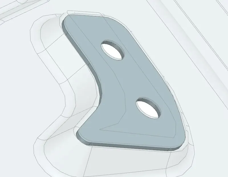
Fig:29-Hinge Reinforcement
2-Striker Reinforcement:
The thickness of the Striker Reinforcement is 1.5mm.
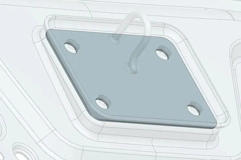
Fig:30-Striker Reinforcement
2. Outer Panel:
The Outer panel is the Upper styling part of the Automobile. This outer panel data is used to design the Inner Panel of the car. It is placed above the Inner Pannel which covers the main Engine Compartment.
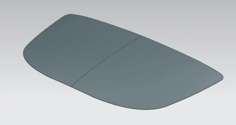
Fig:31-Outer Panel in NX CAD
Hemming:
Hemming is a process which is used to join the Outer and the Inner Panel in the Automotive Industry. It is done by bending the outer panel across the inner panel edges by using the Rollers. Multiple rollers make several passes and this process is completed. This process is prefered over spot welding techniques which creates residual stresses.
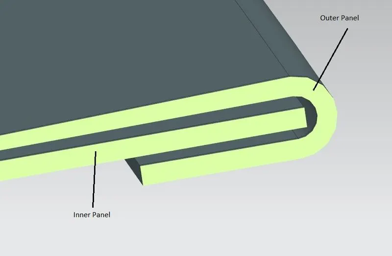
Fig:32-Hemming
The rollers generally complete 3 passes to complete the hemming operation. At the Corner points of the Hemming, the stresses are high. Inorder to reduce the stress generation and the force the Outer panel is given relief at the rear and the front section to optimize the design of the hood after performining the simulation studies.
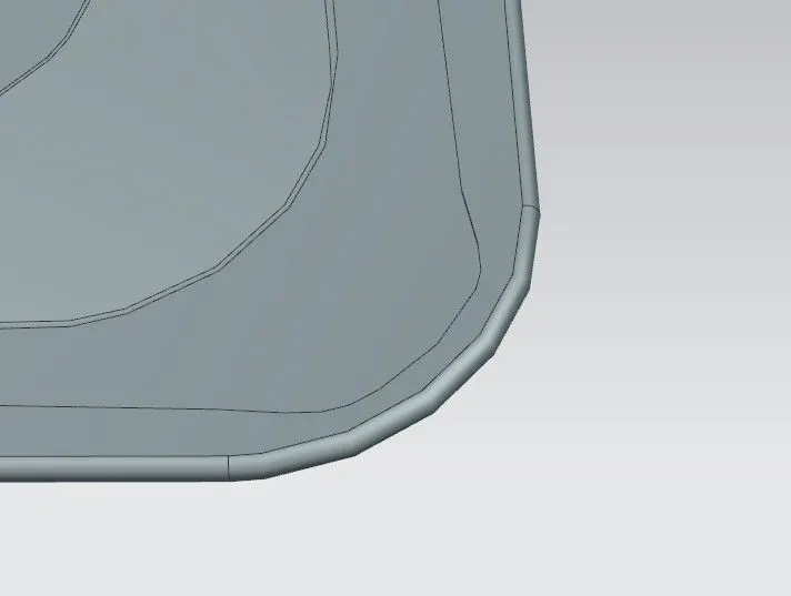
Fig:33-Rear Relief
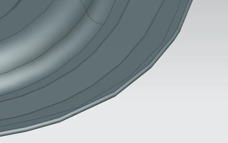
Fig:34-Front Relief
Deep Drawing:
It is a sheet metal manufacturing process in which a sheet metal blank is radially drawn into a forming die by the mechanical action of a punch. It is thus a shape transformation process with material retention. The process is considered "deep" drawing when the depth of the drawn part exceeds its diameter. This is achieved by redrawing the part through a series of dies. The flange region (sheet metal in the die shoulder area) experiences a radial drawing stress and a tangential compressive stress due to the material retention property.
Single Acting Die Assembly:
The blank is produced on a separate press. The blank holder pressure prevents wrinkling.
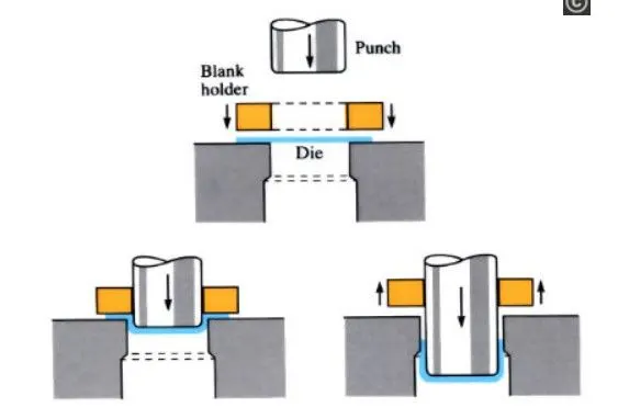
Fig:35-Single Acting Deep Drawing
Double Acting Die Assembly:
The blank is produced in the same die. The outside punch acts as a blank holder.
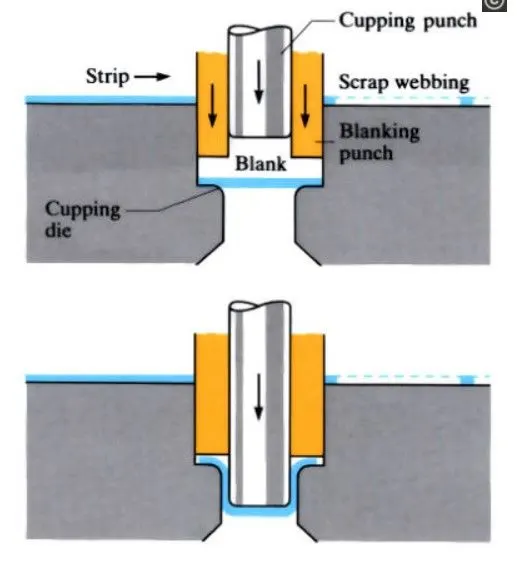
Fig:36-Double Acting Deep Drawing
Final Hood Assembly in NX CAD: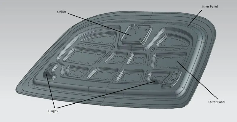
Fig:37-Hood Assembly
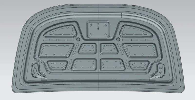
Fig:38-Front View
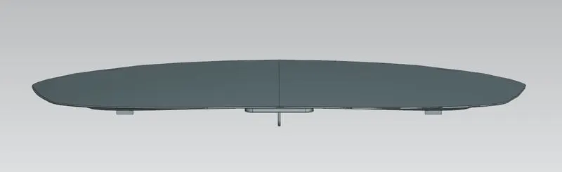
Fig:39-Top View
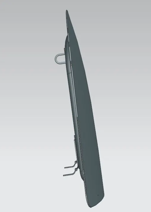
Fig:40-Side View
Draft Analysis:
It is the process of checking the draft angles of the part designed in the software. It should be ensured that there are no negative drafts or the angles in the inner panel of the basic hood. If there is a negative draft shown by red region then it will not be possible to manufacture the part by deep drawing as the tool will get stuck inside the part. The Protruding angle should be maintained at 5-7 Degrees for effective manufacturing.
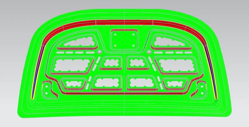
Fig:41 Green Region Shows positive Draft Analysis for the basic inner panel design
Section Modulus Analysis:
This Analysis is done to find the moment of inertia of the section formed by the outer surface of the inner and the outer panel. A section is created by joining the opening sketch and ignoring the thickness.
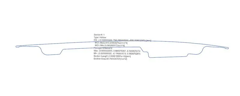
Fig:42-Section Sketch
This analysis is used to determine the moment of inertia of the section which can be used to optimize the volume value of the Hood.
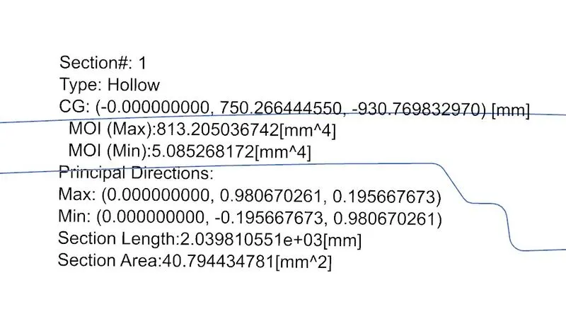
Fig:43-Section Inertia Analysis Results
Conclusion:
The Complete Hood was designed and assembled considering all the Design standards. Performed Draft analysis and Section Modulus Analysis to test the efficiency of the Hood Design using NX CAD.