Section Modulus calculation and optimization
Aim:
To perform Section Modulus Analyisis on the Hood designed in NX CAD
Objective:
The main objective of this project is to perform the Section modulus analysis for the Hood Design and to improve the design by analyzing the Section Inertia Analysis Results.
Introduction:
Section Modulus:
It is defined as the geometric property of the given cross-section of any shaft, beam or structures under consideration. It is also called as Polar Modulus or Torsional Sectional Modulus. It is the direct measure of the strength of the shaft section or the beam section.
There are two types of Section Moduli:
Elastic section Modulus (S) and Plastic Section Modulus (Z). For the bending of steel and Automotive sheet metal Design by Deep Drawing process, Elastic Section Modulus is taken into consideration.
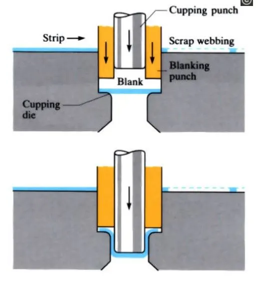
Fig:1-Bending of Steel Sheets
Formula:
Section Modulus is defined as the ratio of the Moment of Inertia to the Distance of the neutral axis from the outer fibres.
S=I/Y
where,
S= Section Modulus
I=Moment of Inertia
Y=Distance between Neutral axis and outer fibres
Some Common Cross sections and their Section Moduli:
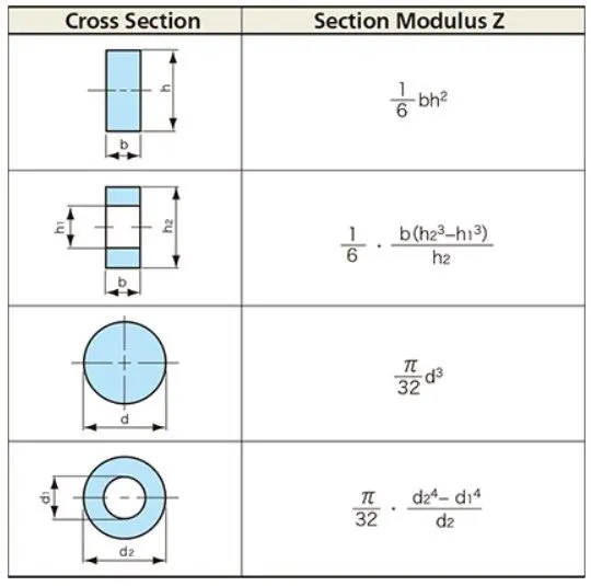
Fig:2-Common Section Moduli
Significance of Section Modulus:
Section Modulus is used to analyze the strength of the sheet metal. More the section modulus harder is the component. For manufacturing of the sheets in Automotive industry Steel is used to manufacture the components. Door beams, roofs and even body panels created during auto manufacturing are made of steel on most cars today. Steel is also used in a variety of areas throughout the body to accommodate the engine or other parts. For a given Hood Design if the Section Modulus is higher then its Strength is higher.
Section Inertia Analysis in NX CAD:
This analysis is used to find the Principal Moment of Inertia, Circumference, Area and Center of Gravity of the Sections.

Fig:3-Section Inertia Analysis (NX CAD)
Analysis for Side Crash:
For side crash, the middle section of the Hood Inner Pannel and Outer Panel is projected on the YZ Plane. The Outer surface of the Inner Panel and the Outer Panel is used to create the sketch by ignoring the thickness. The gaps between the sketch are joined by using a spline curve. For section modulus calculation the minimum or the threshold moment of inertia is used.
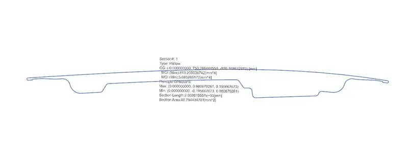
Fig:4 Sketch for Side Crash
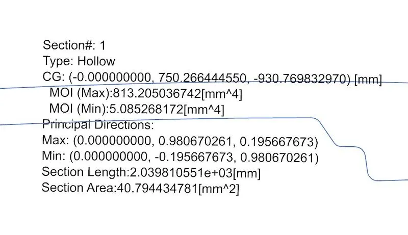
Fig:5-Results for side crash
The minimum moment of inertia, M is 5.0852 mm^4.
For a unit distance from the neutral axis, Y=1mm
The Section modulus is:
S=5.0852/1=5.0852mm^4
Analysis for Frontal Crash:
For Frontal crash the section is taken in the XY Plane by projecting the curves on this plane and completing the Sketch to obtain a closed loop.
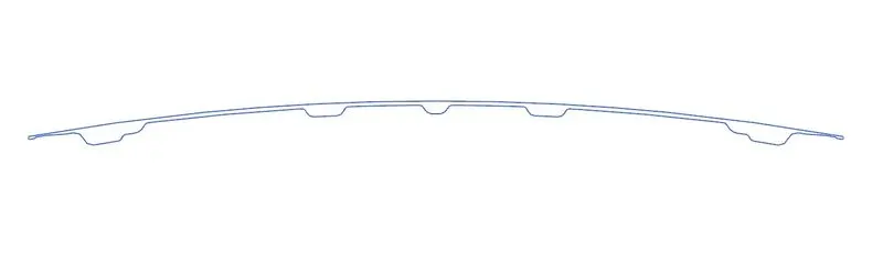
Fig:6-Sketch for Frontal Crash
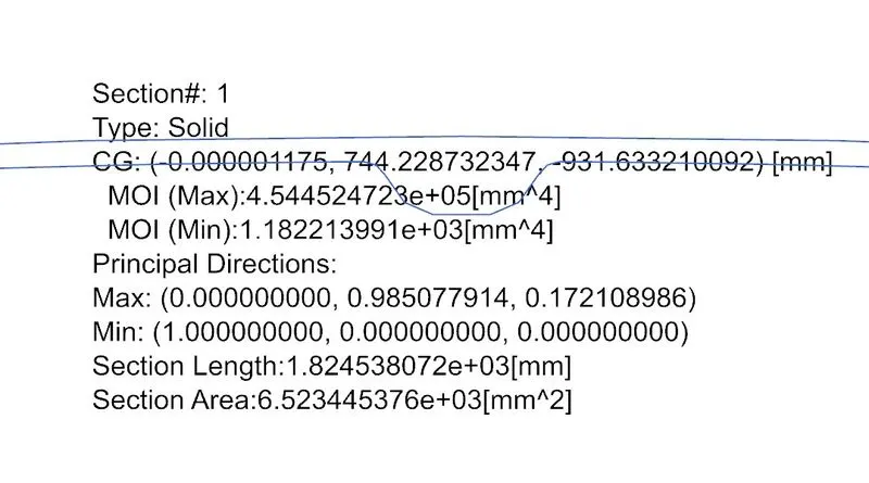
Fig:7-Results for Frontal Crash
The minimum moment of Inertia, M is 1.1822e+03mm^4.
For a unit distance from the neutral axis, Y=1mm
The Section modulus is:
So=5.0852/1=1.1822e+03mm^3.
Modified Design:
The design is changed by increasing the cross sectional area and increasing the radius of the outer fillets.
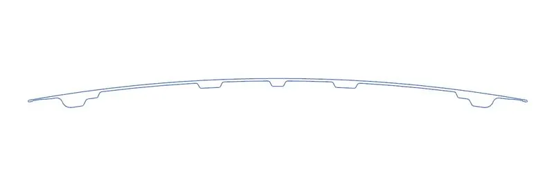
Fig:8-Modified Sketch
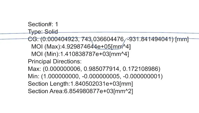
Fig:9-Results of Modified Sketch
For the modified design,
the minimum moment of inertia, M is 1.4108e+03mm^4
For a unit distance from the neutral axis, Y=1mm
The New Section modulus is:
Sn=5.0852/1=1.4108+03mm^3.
Increase in the Section Modulus:
Change in Section Modulus=Sn-So=(1.4108e+03)-(1.1822e+03)=0.2286e+03mm^4
Conclusion:
Performed Section Inertia Analysis for the Hood Design and modified the design which increased the Section Modulus, thereby increasing the Strength of the Hood.