Fender Design Challenge
Aim:
To Design the Front Fender of an Automobile considering the Design Standards.
Objective:
The main objective of this project is to Design the Front Fender of the car using the Skin data and the Master section.
The Fender should have following mountings:
- Drip
- A-Pillar
- Sill
- Bumper
- C mounting
- Splash mountings
Introduction:
Body in White (BIW):
Body in white or BIW is the complete assembled body shell ready for painting. It is made up of sheet metal parts most commonly used sheet metal is Steel.

Fig:1-BIW Welding Line
Classification of BIW:
BIW is classified into three main components:
1) Underbody:
This section of the BIW remains close to the ground. It is exposed to tough roads, dust, mud, rust, etc.
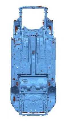
Fig:2-Underbody
2) Upperbody:
This section of BIW consists of all the parts above the base platform of the BIW. Key components of Upper Body are A, B, C, D Pillars, Cant Rail, Side panels, Roof Panel, etc.
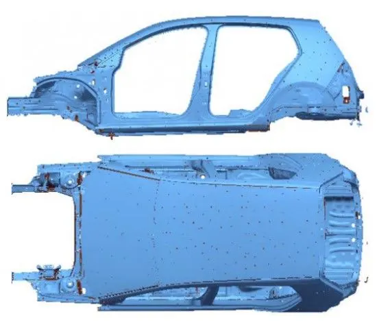
Fig:3-Upperbody
3) Closures:
These consists of all the components which are not part of the main body structure. These are not welded or bolted on to the underlying structure of the vehicle. In simple words these are components which can undergo opening and closing in a BIW Layout. Main Closures are Hood (Inner/Outer Panel), Doors, Fuel door, Tailgate and Fender. Fender however is fixed to the main BIW structure but it is considered as a closure component.
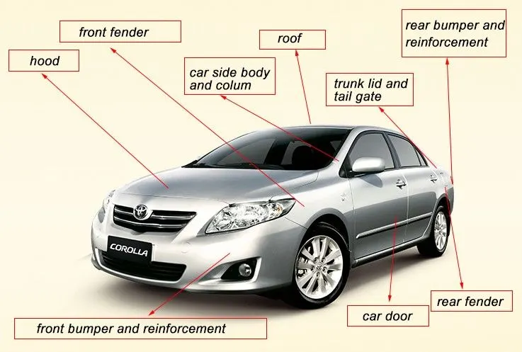
Fig:4-Closures Layout in COROLLA
Fender:
Fender is the part of the Vehicle Body which frames the wheel well (Fender Underside). The term Fender is a US English word and it is a Closure component.
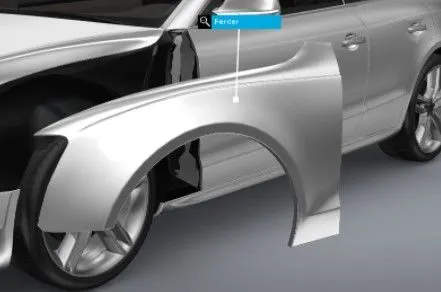
Fig:5-Fender
When the car is under motion, the tires pick up stones and other particles and throw them in all directions. The main purpose of the Fender is to prevent sand, mud, rocks, liquids and other road spray from being thrown into the air by the rotating tire. This prevents injuries to pedastrians and contain the motion of the particles. It prevents chipping inside the Engine compartment.
Most of the passenger cars have four Fenders, which is present above every wheel. If the vehicle has a narrow car body then the front fender is an exposed curve over the top of the tire. For wide body cars that cover the tire, the fender forms a wheel well which surrounds the tire and it is not directly visible from above the car body.
Types of Fenders:
Based on Position:
1. Front Fender:
This Fender is placed at the front part of the car. It is present above the front wheels on both sides of the Hood or Bonet of the car.
2. Rear Fender:
This Fender is placed above the rear wheels. These Fenders are integrated with the body.
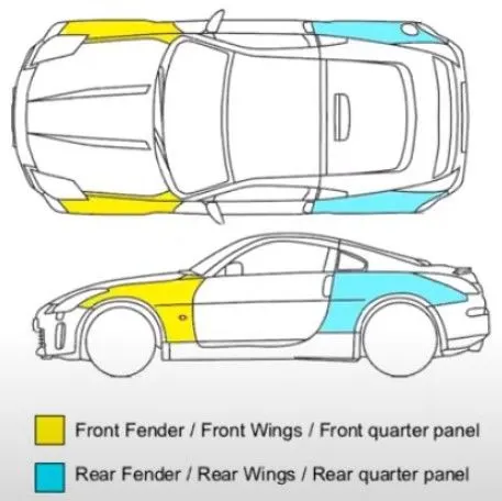
Fig:6-Front and Rear Fender
Based on Shape:
1. Full Bumper type:
These types of Bumper require more material and a single blank sheet is used to manufacture these Fenders.
2. Half-Bumper type:
At the same time two identical Half Bumper type Fenders can be manufactured by using a single blank of metal. These fenders are prefered over full bumper type because of their low cost of production. The weight of this Fender is lower than the earlier one and the fuel efficiency of the vehicle increases as the remaining portion is composed of High quality plastics in place of Steel.
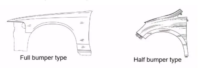
Fig:7-Full and Half Bumper type Fenders
Design Asepect of Fender:
Crash tests are preformed for Frontal Crash and Offset Crash of an Automobile to improve the car quality for safety of the passengers and the pedastrians. The Fender Designer has to ensure that most of the energy is dissipated outwards during the crash and the passengers are safe with least impact on them.
In an offset crash only one side of a vehicle's front end, not the full width, hits the barrier. As a result, a smaller part of the structure has to manage the crash energy, and intrusion into the occupant compartment is more likely.

Fig:8-Frontal Offset Test (EURO NCAP)
The Fender is designed such that it collapses outwards after the crash.


Fig:9-Crash test Results
Manufacturing of Fender:
1. First the applicable cold coiling is specfied. Then based the material specification the flat cold coiling will be cut into Iron flat plates of required sizes.
2. Then the iron plates are extended. It is trimmed, punched, flanged and the shaping process is completed. Holes are pierced for the mountings.
3. Blanking: The Iron plate is stamped out to required outline blank followed by punching.
4. Panel beating assembly welding: This includes the spot welding of the nuts and other components.
5. Finally the basic part is coated with paint and protective coatings.
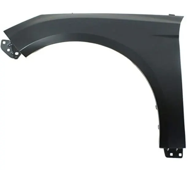
Fig:10-Manufactured Fender
Fender Design:
Input Data:
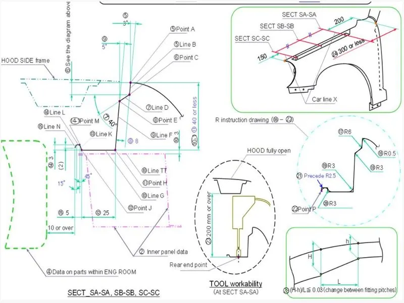
Fig:11-Mater Section to create the drip area
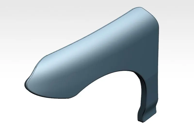
Fig:12-Fender Skin
Thickness of the Fender is 0.65 mm.
Mountings of Fender:
1. Drip Area:
It is a mounting region which is provided to connect the Fender with the Engine compartment. The basic design considerations of the drip area for all the OEMs (Original Equipment Manufacturer) are same. The Drip area should be at a distance of 200 mm from the Cowl Top Region and 150 mm from the front housing unit. Cowl is the space between the Hood and the Windshield. The basic length of the Fender varies from car to car.
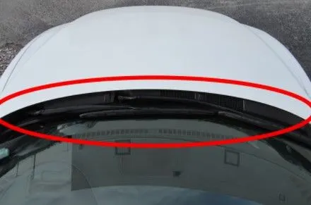
Fig:13-Cowl Region
For maximum productivity the Hood Side Drip depth must be 40 mm or less than that. It is the effective depth for stamping of the component. Also, if the depth exceeds 60mm it leads to Spring back effect. The Spring back effect is phenomenon in which the Hood side region deforms repeatedly due to Vibrations. The Land area is also given a width 0f 35-40mm for effective working of tools to be operated in the inner drip area region.
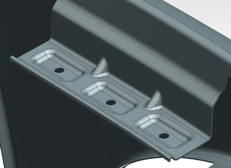
Fig:14-Drip area in NX CAD
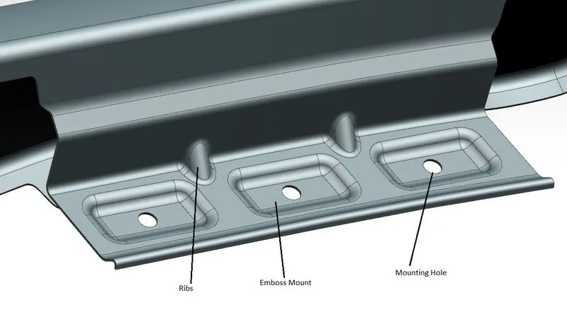
Fig:15-Drip area points
Mounting holes are provided to mount the fender with the engine compartment. Ribs are additional protrudings which adds to the strength of the design. Embosses are created to punch the holes and for increasing the local strength.
2. A-Pillar Mounting:
This mounting is provided to connect the Fender with the A-Pillar of the BIW layout. It has a mounting hole and rib.
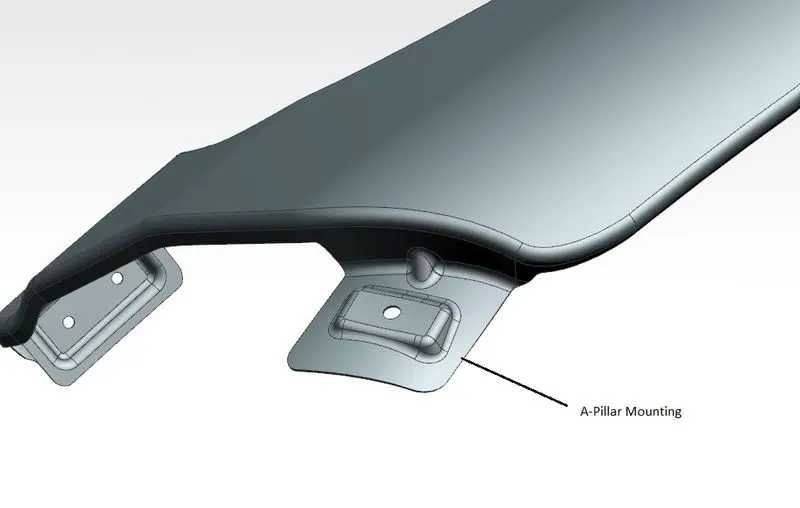
Fig:16-A-Pillar Mounting Position
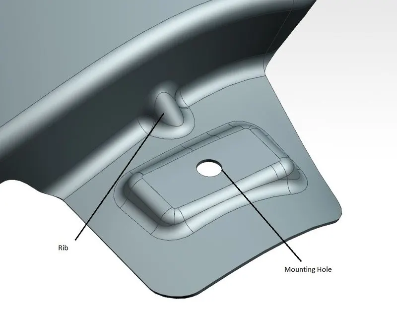
Fig:17-A-Pillar Mounting
3. Bumper Side Mounting:
This mounting enables the connection of the Fender with the Bumper of the Automobile.
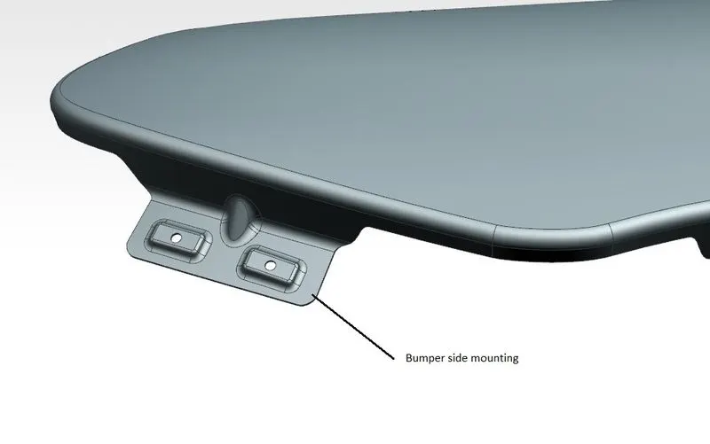
Fig:18-Bumper side mounting position
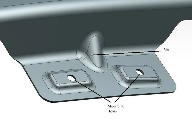
Fig:19-Bumper Side Mounting
4. Sill Mounting:
This mounting is provided to join the Fender with the Sill of the Car. The Sill is a part of the car frame located at the bottom of the doors.
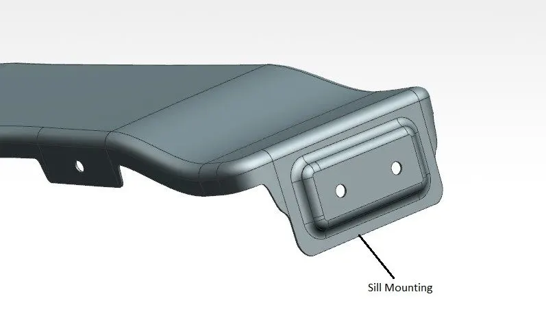
Fig:20-Sill Mounting Position
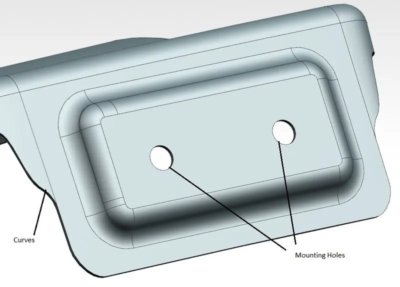
Fig:21-Sill Mounting
It is ensured that all the parts are provided with smooth curve regions with no sharp corners to reduce the stress generation.
5. Baffle Mounting Area:
This mountings are present to attach the Baffle to the Fender. The Baffle is a plastic part which is used to protect the wheel arch area from the dust, mud, sand and other particles. Baffles mainly obstruct the fluid flow or changes its direction. Since, the Baffle is a Plasic Part there is no need to provide embosses for the Mounting Holes for Baffle Points.
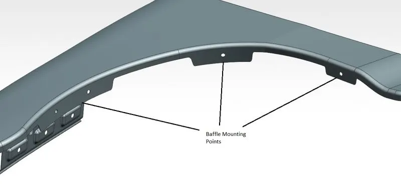
Fig:22-Baffle Points
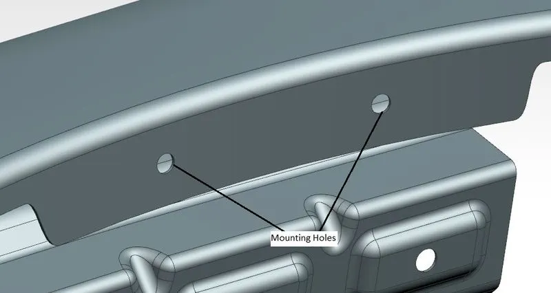
Fig:23-Baffle Mounting
Fender Views:
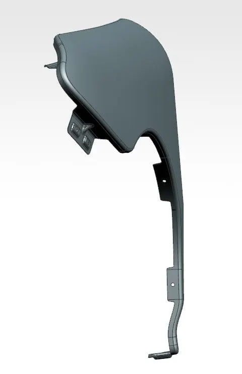
Fig:24-Front View
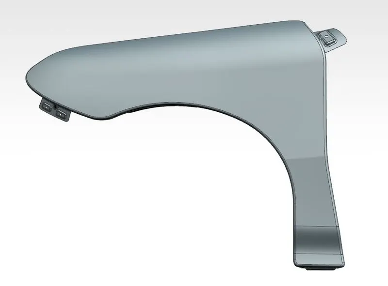
Fig:25-Side View
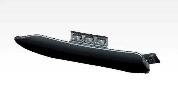
Fig:26-Top View
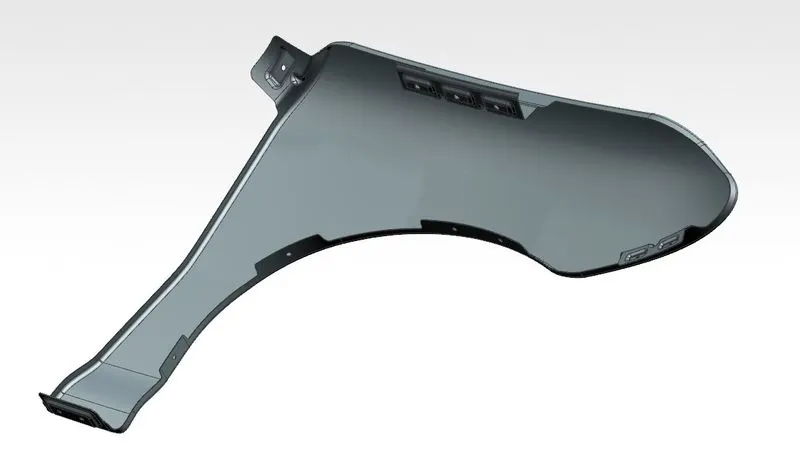
Fig:27-Inner View of the Fender
Conclusion:
The Front Fender was Designed with all the mountings considering the Design standards in NX CAD.