Roof challenge
Automotive Roof Design
Aim: To design & develop the Roof of a car with its components by following the master section and design parameters.
Objective:
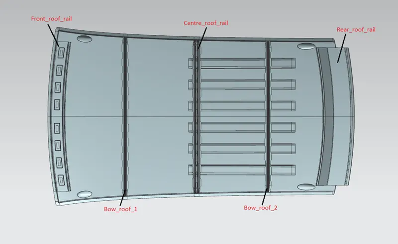
- For the given Car Roof styling, design and develop the essential flanges and reinforcements, namely the Front Roof Rail, Rear Roof Rail, Centre Roof Rail and Bow-Roofs.
- Do a Section Inertia study for the Master sections created for the Front Roof Rail, Rear Roof Rail, Bow Roof Rails and Centre Roof Rail
- Do a curvature study on the roof and perform calculations for Heat Distortion and Snow load criterion to determine and justify the position of the Bow-roofs.
Introduction:
An automobile roof is the portion of an automobile that sits above the passenger compartment, protecting the vehicle occupants from sun, wind, rain, and other external elements. Under the styling surface that is seen on the outside, there are many other structures under the roof which contribute to its strength and stability. The roof of the car is made up of multiple parts that provide support and strength to the roof component. The roof panel is attached to the BIW of the car with the help of front and rear roof rail. This attachment is done with the help of sealants. The actual roof sheet and the roof rails support the roof sheet. There are 3 primary roof rails in a car the front, the centre, and the rear, while additional roof rails are called Bow roof rails. The number of bow roof rails depends on the size of the roof. Longer the roof, more the number of bow roof rails. Other dimensions like strength and material are governed by the factors like headroom, overall space, visibility, ergonomics and the rules and regulation of the states where it is sold. Some roofs have a window on them and are called sunroofs, while convertibles have special mechanisms that allow the roof to be retracted and be stowed away through a wide array of methods depending on the design.
Roof Parts
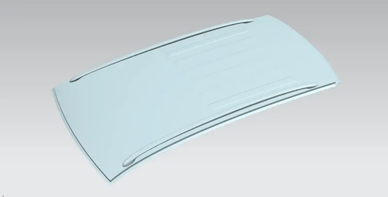
ROOF OUTER PANEL:
FRONT ROOF RAIL:
Front roof rails are used in the assembly of a roof in which it provides mounting provisions to windshield glasses and. It is designed with support requirements, visibility criteria, and headroom space in mind. The major design factor considered is the headroom clearance. The front roof rail also provides provisions for mounting the inside rear-view mirror. It is usually made from Body Side Outer scrap and therefore the thickness of the rail is 0.75 mm. A draft angle of 3-5 degrees is provided keeping in mind the deep drawing operation. The Wind Shield end flange is the exact offset of the roof surface. The bottommost flange is decided after taking into consideration the visibility criteria and the Headroom Clearance of the passenger. Spot Welds are applied at Wind Shield end of the rail and the other end is joined with the roof using Mastic Sealants which also contributes to increased strength.
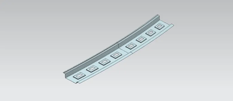
BOW ROOF RAIL:
The bow roof rails provide additional support to the roof and they are positioned in such a way that they provide maximum support to the roof. Care must be taken so that they do not intrude into the headroom requirements of the car. Bow roof rails are an optional feature provided as required by the design. Small cars may have none while large ones may have 3 or more, they may also be integrated into the centre roof rail in some cases. The roof is fixed to the roof rails with the use of mastics while the ends are spot welded.
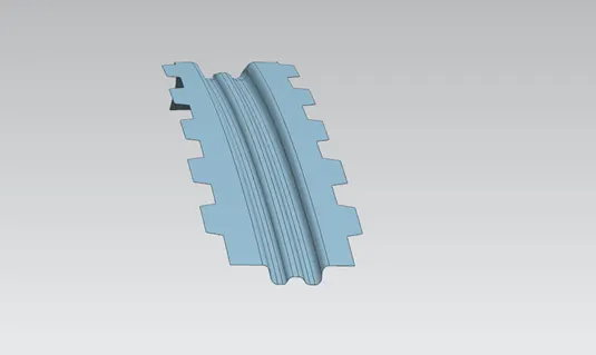
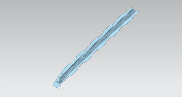
CENTRE ROOF RAIL (REINFORCEMENT CENTER):
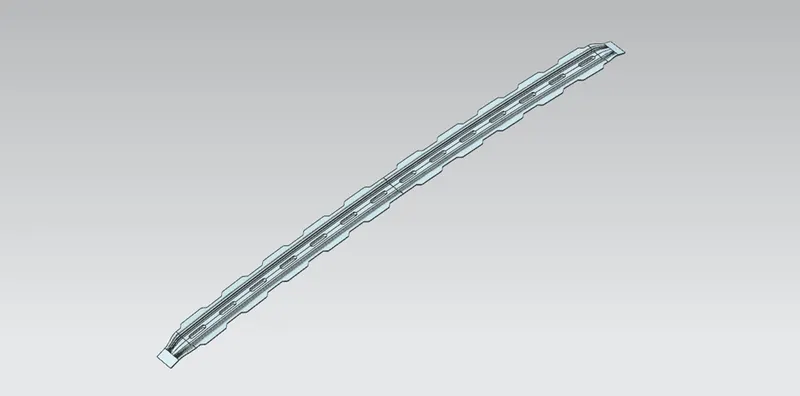
The reinforcement centre is used as a cross member between bodyside LH & RH respectively. Similar to other Rails design, we have to take into consideration the Headroom Clearance and the visibility criteria while designing the Centre Roof Rail and Bow Roofs. But unlike the Front and Rear Roof Rails, Spot Welds are not applied for joining these rails to the roof. Instead, Mastic sealants are introduced at both the ends since Centre Roof Rail and Bow Roofs are fully positioned under the Styling surface of the Roof. For increasing the strength of the rails, embossing is done. To reduce the weight of the material used, a different styling has been followed with a thickness of 0.75 mm.
REAR ROOF RAIL:
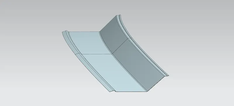
It is the support which is joined to the Back Door and the Body Side Outer and the inner panels. It is also usually made from Body Side Outer scrap and therefore the thickness of the rail is 0.75 mm. Similar to the Front Roof Rail design, we have to take into consideration the rear Headroom Clearance and the rear visibility criteria while designing the Rear Roof Rail. Inputs from the backdoor design is also taken to accommodate the required clearance. Spot Welds are applied at the Back door end of the rail and the other end is joined with the roof using Mastic Sealants. The Rear roof rail is used to provide strength to the roof panel front and it also acts as a link between windshield glass, roof panel, and headliner.
ASSEMBLED ROOF:
MOMENT OF INERTIA:
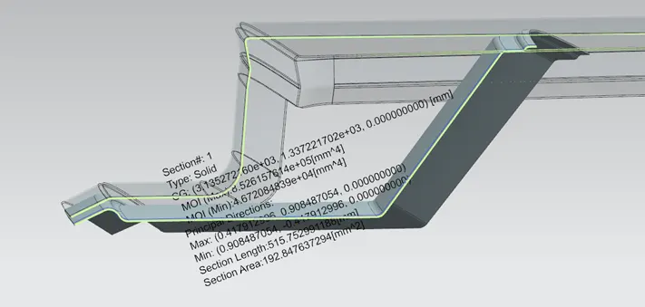
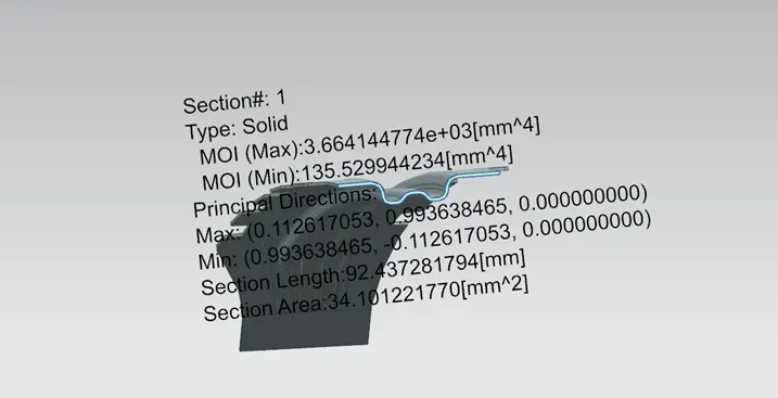
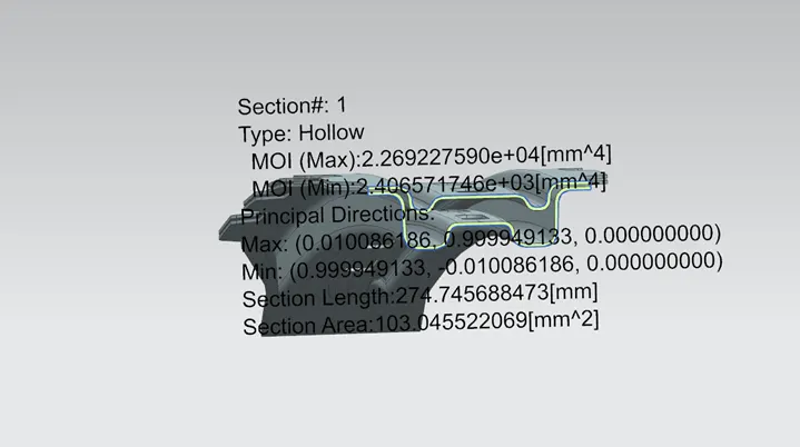
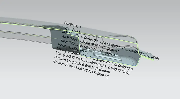
Section moment of inertia is used to predict the amount of deformation and deflection of a part. A higher moment of inertia is preferable as it reduces the amount of deflection for a given force. The thickness of the part and the addition of flanges and embosses increase the section inertia of the part. Here the master sections of the roof and roof rails and their section analysis are given.
Section inertia of the Front Roof Rail, Rear Roof Rail, Bow Roof Rails and Centre Roof Rail are as follow
Front Roof Rail
Bow Roof Rails 1 & 2
Centre Roof Rail
Rear Roof Rail
Analysis:
It is done to justify the positioning of the Bow Roofs. There are mainly three criterions to fulfil
- Roof Crush Test
- Heat Distortion Test
- Snow Load Criteria
1. Roof Crush Test: Roof Crush Testing is done only after the part or prototype is manufactured in physical conditions.
2. Heat distortion condition: Heat distortion temperature is the temperature at which the metal softens and deforms under a specific load. Roof of a car is probably the only component which is exposed to sun for almost all the time, so this study is done to check the ability of the roof to withstand high temperature with respect to the positioning of the reinforcements which contribute to increased strength.
Prediction Formula:
W = [1.73 x 10^ (-3) x L] + [1.85 x 10^ (-8) x (R^2)/t] + [ 1.10x10^(-3) x l] - 2.68
Judgement Condition: OK< 2.7> 3.1
Where,
L = Roof Length in X-Direction [mm] (Roof dimension in 0-Y)
R = Roof curvature
R= 2(Rx*Ry) / (Rx+Ry)
Rx = X curvature
Ry = Y curvature
t = Roof plate thickness (mm)s
l = Bow Roof Span (mm)
Curvature study of the roofs are mentioned below for calculation purpose
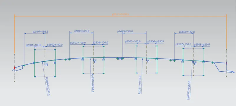
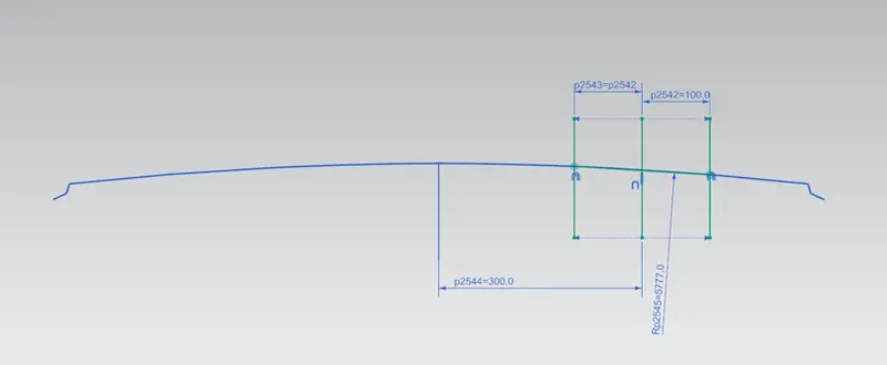
Taken all the Rx values for calculation as same as the above method

When applying the corresponding measurements into the formula, the criterion is met for all the reinforcements
3. Snow Load Criteria: Snow load criteria study is done to check the ability of the roof to withstand snowfall and bounce back to its original shape without any permanent deformation once the load is removed.
Prediction Formula:
Qr = [Iy x t2] / [α x s x [(Rx + Ry)/2]2 x 10-8]
Where,
α = My x Lx2 x 10-12, My = Y(Ly-Y)
Judgement condition = Qr ≥ 3.1, 250 ≤ s ≤ 380
t = Roof plate thickness [mm]
Ly = Distance between the front and rear roof Rails on the Vehicle along with 0Y[mm]
Length of Roof panel with the centre point between Roof rail Front /Rear as the front and rear reference point.
Lx = Distance between the Left and Right end of the roof on the Roof BOW [mm]
Width of the roof panel exposed on the surface.
Y = Distance Front Roof Rail to Roof BOW [mm]
s = Distance for which Roof BOW bears divided load [mm]
s = L1/2 + L2/2
Iy = Geometrical moment of inertia of Roof BOW (Y cross-section) [mm4]
Rx = Lateral direction curvature radius of roof panel Y cross-section on Roof BOW [mm]
Roof panel curvature Radius of the Length Lx in Front view
Ry = Longitudinal Direction curvature radius of the Roof panel X cross-section on Roof BOW [mm]
Roof panel X curvature radius of length s in Side view
Curvature study of the roofs are mentioned below for calculation purpose
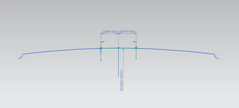
Taken all the Rx values for calculation as same as the above method

In the third condition the snow load condition is not satisfied, hence roof embose is provided to strenghten the roof.
Conclusion: The car roof has been designed by taking consideration of all the design parameters and perform the curvature study on the roof and checked for Heat Distortion and Snow load criterion. Design passed the heat load criteria but failed at some sections in snow load criteria. To overcome this, embosses are provided on the roof surface.