Radar Mast & Final Assembly of Yacht
Assembly of Yacht
OBJECTIVE:
- Design the individual part of Yacht with fully define using Solid works.
- Assembling of all the individual parts of the Yacht model by assigning suitable to constraints.
- Render the Yacht model by adding the suitable environment, decals & additional lights, cameras & background scenes.
INTRODUCTION:
Solid works: Solid works is modeling software published by Dassault System Company. This software is mainly used to create 3D model using 2D sketch. It also has the option to specify the material and look for the model which we create. It has other Add in features like photoview360 which helps in rendering of final model to make it look photo realistic. In this project we learnt about detailed design of American chopper parts and assembling them and rendering the final chopper after assembly.
Yacht: Yachts originated from the Dutch Jatch type of vessel which has designed for sports and to stay overnights with all the luxurious facilities.
DESIGN METHODOLOGY:
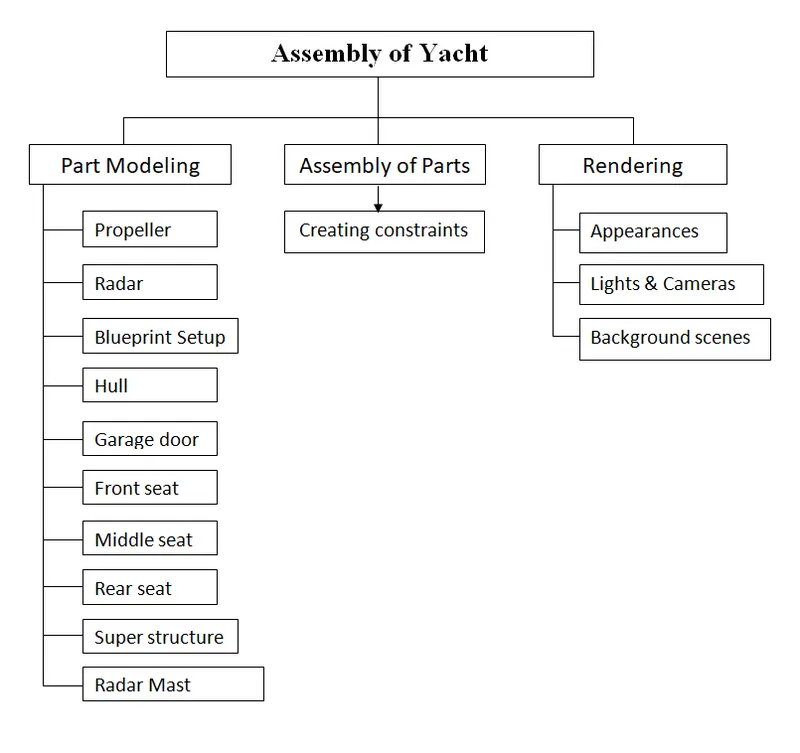
DESCRIPTION:
I) Part/Surface Modeling:
A) Part modeling: Part modeling you can create a part from a conceptual sketch through solid feature-based modeling, as well as build and modify parts through direct and intuitive graphical manipulation.
B) Surface modeling: Surface modeling gives you the ability to build out a visual representation of an object’s exterior and its contours. In other words, it’s a surface. Surface modeling plays a major role in modeling a Yacht. Most of the parts in yacht are surface modeled.
Explanation of tools and features used while designing:
Tools used:
1. Sketch: Used to create a 2D sketch by using sketch tools.
2. Line: Used to draw lines. Different types of lines are mentioned below.
-
- Centre/Construction line
- Midpoint line
3. Circle: Used to draw circles. Different types of circles are mentioned below.
-
- Centre point circle
- Perimeter circle
4. Arc: Used to draw arc. There are 3 types of arc
-
- Centre point arc
- Tangent arc
- 3 point arc
5. Rectangle: To create rectangles. Types of rectangles are mentioned below
-
- Centre rectangle
- Corner rectangle
- 3 point corner rectangle
- 3 point center rectangle
- Parallelogram
- Spline: It is a special type of sketch entity which is used to draw smooth curves through interpolation of points.
- Straight slot: To sketch a straight slot.
- Fillet: To create smooth or round edges at the intersection of two sketch entities.
- Chamfer: It is used to cut a sharp edge/face usually at a 45° angle to the adjacent principal edge/face or a cut on the edge or corner of something that makes it slope slightly rather being perfectly square.
- Trim/Extend: Trims/Extends a sketch entity to be coincident to another.
- Convert entities: To convert selected model edges or curves into sketch segments
- Offset entities: To add sketch entities by offsetting faces, edges, curves at a specified distance.
- Intersection curve: To get an intersection curve obtained from projection of two curves.
- Mirror: To mirror entities about an axis.
- Dynamic mirror: Mirrors entities dynamically. It creates mirrored entities at a same time while drawing.
- Sketch pattern: To create a pattern of sketch entities along a linear/circular reference. Types of patterns are mentioned below
-
- Centre point circle
- Perimeter circle
-
- Smart dimensions: Used to add or edit dimensions of sketches.
Features used (Part modelling) :
- Extruded Boss/Base: Used to create 3D solid from 2D sketch. It extrudes a selected sketch in one or two direction to create a solid feature.
- Swept Boss/Base: Used to create a solid body along the profile path.
- Revolved Boss/Base: Revolves a selected sketch around an axis to create a solid body.
- Extruded cut: Cuts a solid model by extruding a sketched profile in one or two direction using 2D sketch.
- Revolved cut: Cuts a solid model by revolving a sketched profile around an axis.
- Lofted cut: Cuts a solid model by removing material between two or more profiles.
- Reference plane: It is used to construct a plane when the existed planes are not suitable to create sketches/features.
- Mirror: To mirror the features about a plane.
- Combine: To combine two or more solid bodies.
- Dome: To create dome surfaces on flat surfaces.
- Split: To create multiple bodies from a single body.
- Pattern: To create a pattern of features, faces and bodies in one or two direction along a reference path. Types of patterns are mentioned below
-
- Linear pattern: To create a pattern of feature/body along a linear reference.
- Circular pattern: To create a pattern of feature/body along a circular reference.
- Curve driven pattern
- Sketch driven pattern
- Variable pattern
-
- Chamfer: To convert sharp edges into bevel edges.
- Composite curve: Used to obtain combined composite curve from two or more curves.
- Projected curve: It is a tool use to form 3D curves from two 2D curves from two different planes.
- Smart dimensions: Used to add or edit dimensions of sketches.
Features used (Surface modelling):
- Extruded Surface: It extrudes a selected sketch in one or two direction to create a surface.
- Swept Surface: Used to create a surface along the profile path.
- Lofted Surface: These surfaces are generated by multiple 3D curves or existing edges creating a smooth tangency between the selected curves.
- Filled Surface: In this command we can create a surface by providing a set of edges which forms a closed area.
- Ruled Surface: Used to insert a ruled surfaces from edges.
- Extend Surface: Used to extend the surface which is already created. We can extend the surface as same sirface or ew can extend the surface tangent to the surface.
- Trim Surface: Used to trim unwanted surface.
- Surface offset: Used to offset the surface
- Reference plane: It is used to construct a plane when the existed planes are not suitable to create sketches/features.
- Mirror: To mirror the features/surfaces about a plane.
- Combine: To combine two or more solid bodies.
- Dome: To create dome surfaces on flat surfaces.
- Split: To create multiple bodies from a single body.
- Shell: Removes material from a solid body to create a thin-walled feature.
- Fillet: To create smooth or round edges at the intersection of two sketch entities.
- Knit Surface: Used to knit (Stitch) two adjecent non intersecting surfaces to each other by considering the tolerance. This reduces the gap between the two edges of the surface.
- Text: Used to add a text on the surface.
- 3D Sketch: Used to create a 3D sketch by using sketch tools.
Designing of all parts and components are as follows:
1) Propeller:
A propeller is a fan mechanism that transmits power by converting rotational motion into thrust. Usually which is consisting of 3 or more blades.
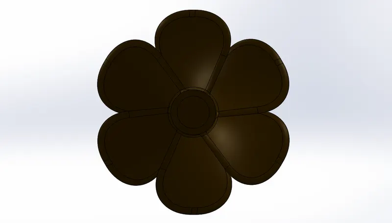 Propeller- Front view Propeller- Front view |
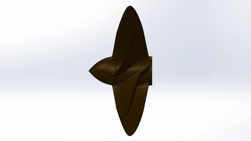 Propeller- Side view Propeller- Side view |
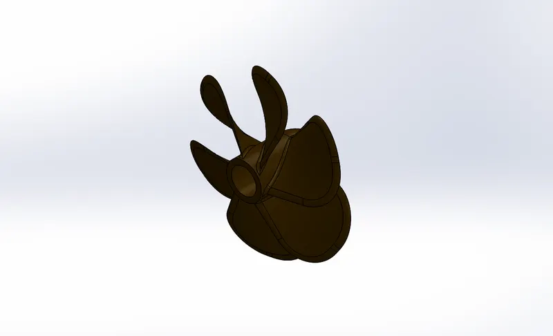
Propeller - Isometric view
Tools and feature used:
|
|
|
|
|
|
|
|
|
|
|
|
2) Radar:
Radar is a system attached on top of the ship to transmit and receive signals several meters of range. It is basically ranging and detecting system which is used in every ship.
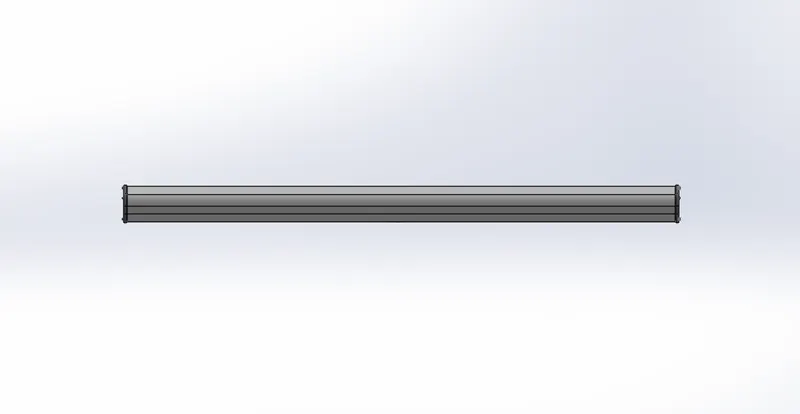 Radar- Front view Radar- Front view |
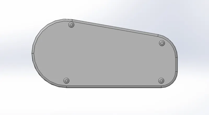 Radar- Side view Radar- Side view |
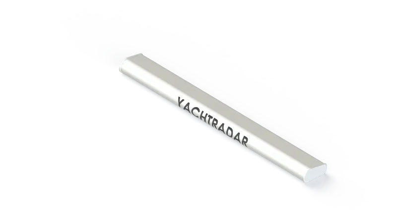
Radar - Isometric view
Tools and feature used:
|
|
|
|
|
|
|
|
|
|
|
|
|
|
|
3) Blueprint setup:
Blueprint picture is required for reference.
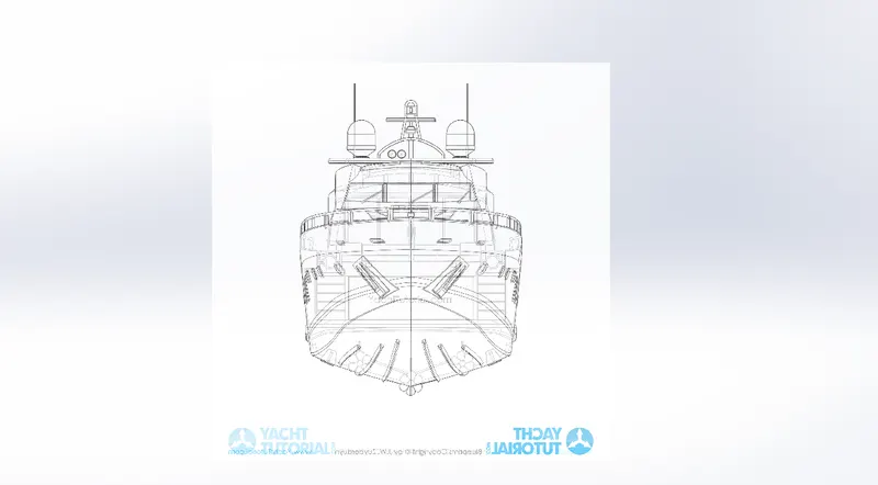 Blueprint- Front view Blueprint- Front view |
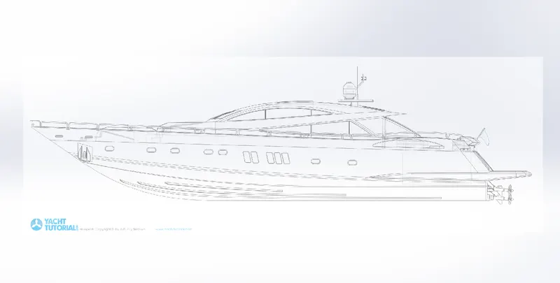 Blueprint- Side view Blueprint- Side view |
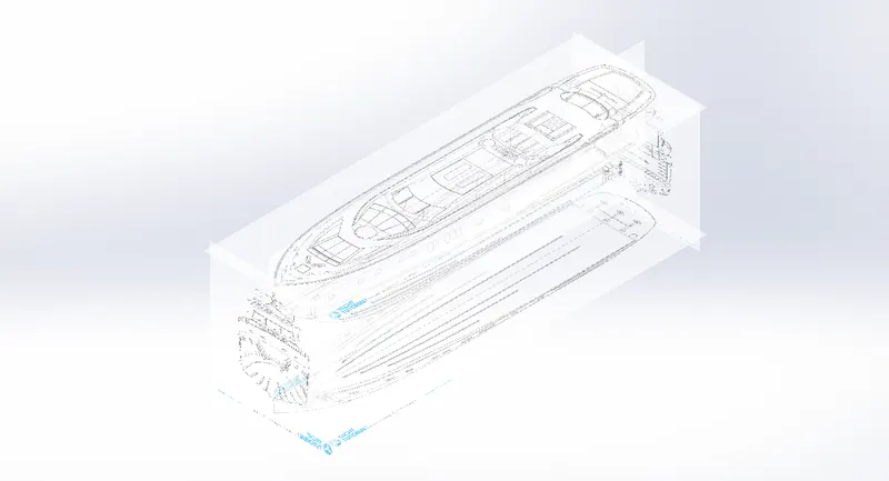
Blueprint - Isometric view
Tools and feature used:
Sketch picture: Insert the picture for reference.
4) Hull:
Hull is a part which is in contact with water body. The hull is supposed to be made watertight. he line where the hull meets the water surface is called the waterline.
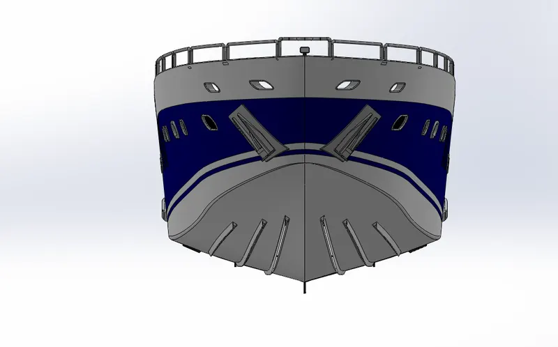 Hull- Front view Hull- Front view |
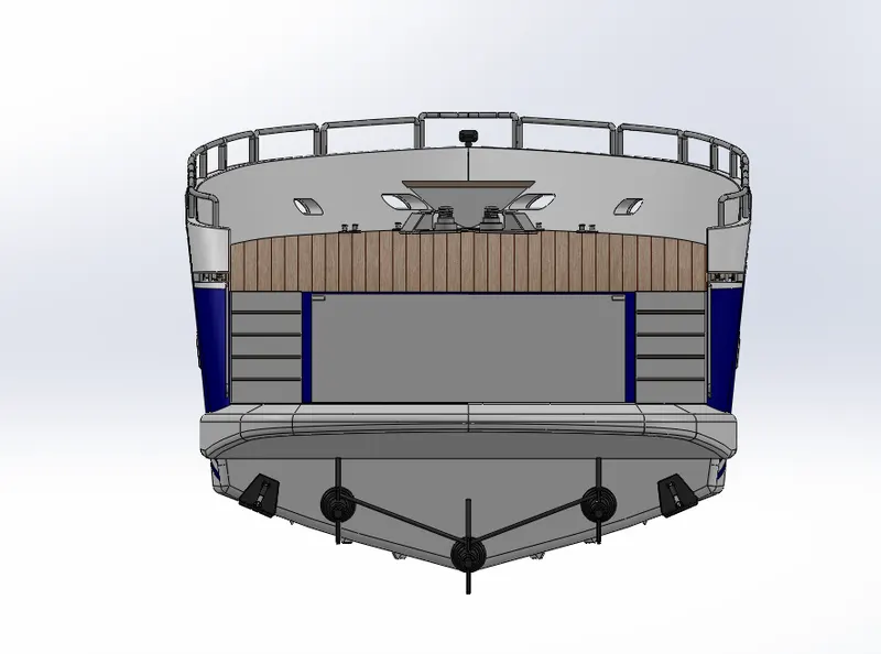 Hull- Back view Hull- Back view |
|
Hull- Side view |
Hull- Side view |
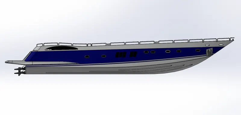
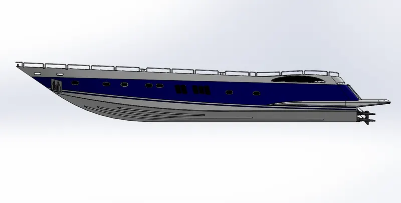
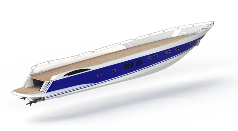
Hull - Isometric view
Tools and feature used:
|
|
|
|
|
|
|
|
|
|
|
|
|
|
|
|
|
|
|
|
|
|
|
|
|
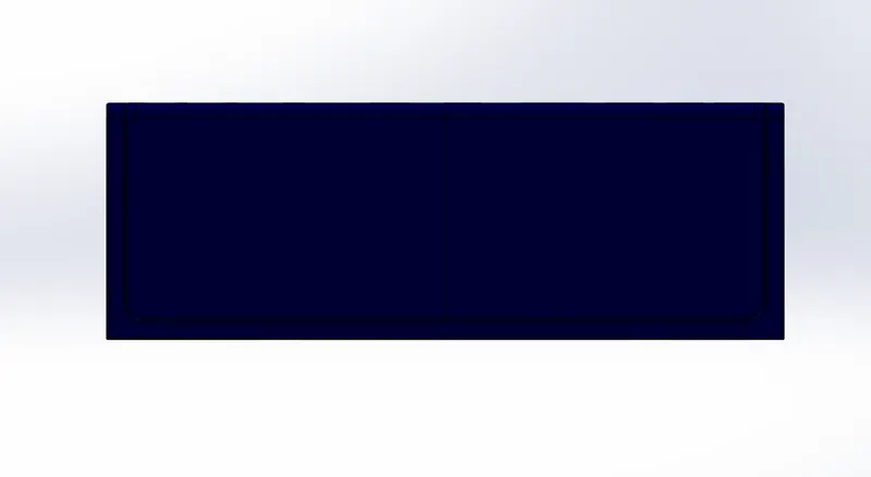
5) Garage Door:
Garage door is a big door attached behind, which either operates manually or with a motor. A garage is usually used to store automobiles in a yacht.
|
Garage door- Front view |
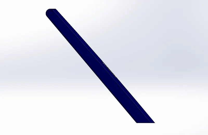 Garage door- Side view Garage door- Side view |
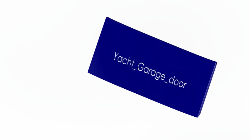
Garage door - Isometric view
Tools and feature used:
|
|
|
|
|
|
|
|
|
|
6) Front, middle and rear seats:
Seats are made for sitting purspose. Front, middle and rear seats are placed at the front, middle and rear side of the yacht respectively.
A ) Front seat
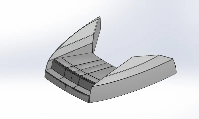 Front seat_ Isometric view Front seat_ Isometric view |
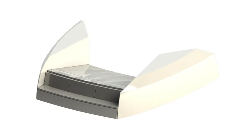 Front seat_Rendered Front seat_Rendered |
B) Middle seat
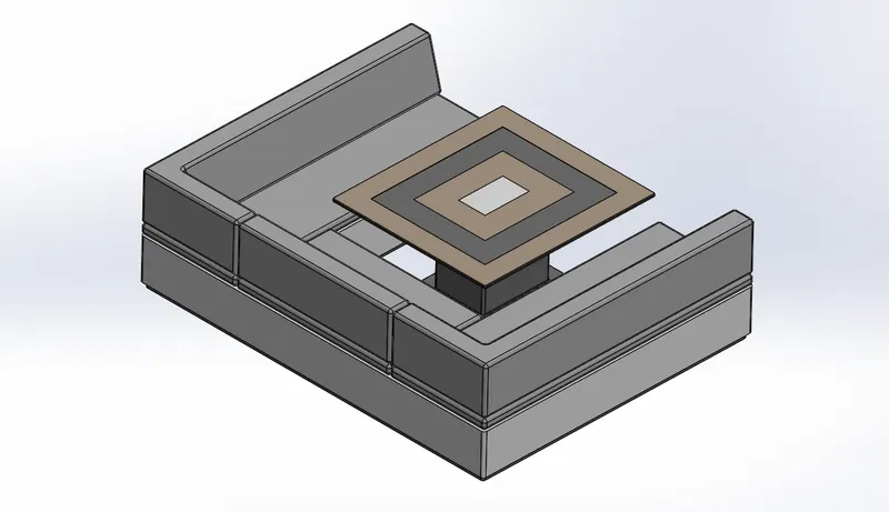 Middle seat_ Isometric view Middle seat_ Isometric view |
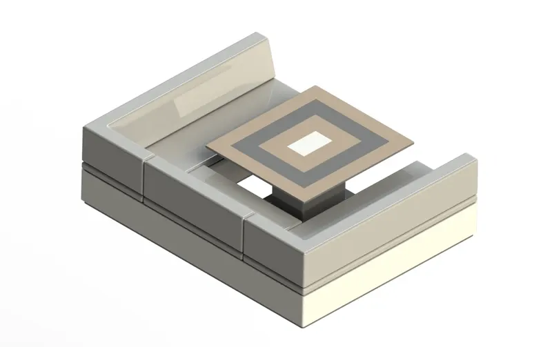 Middle seat_Rendered Middle seat_Rendered |
C) Rear seat
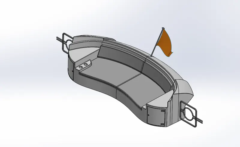 Rear seat_ Isometric view Rear seat_ Isometric view |
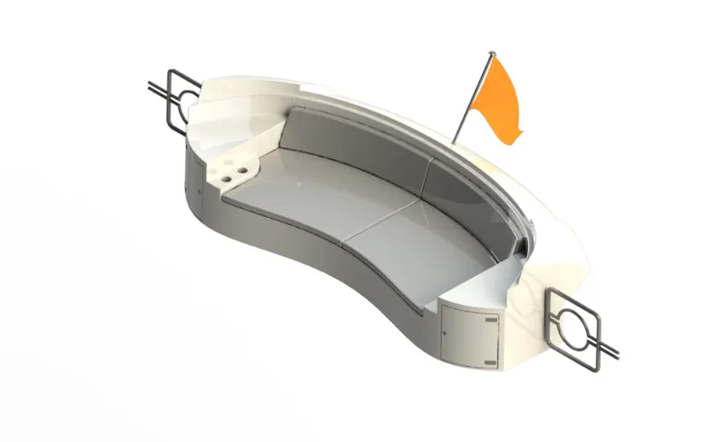 Rear seat_Rendered Rear seat_Rendered |
Tools and feature used:
|
|
|
|
|
|
|
|
|
|
|
|
|
|
|
|
|
|
|
|
|
|
|
|
7) Superstructure:
Superstructure means to add a construction to an already existing structure. In ships this is the name given to the part of the ship that emerges from the deck.
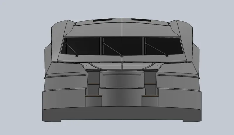 Superstructure- Front view Superstructure- Front view |
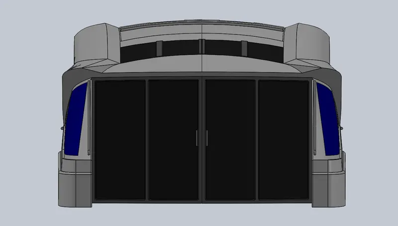 Superstructure- Back view Superstructure- Back view |
|
Superstructure- Side view |
Superstructure- Side view |
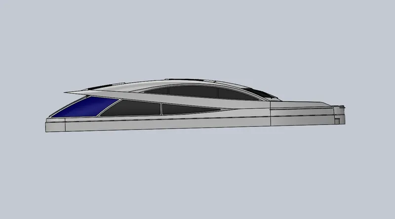
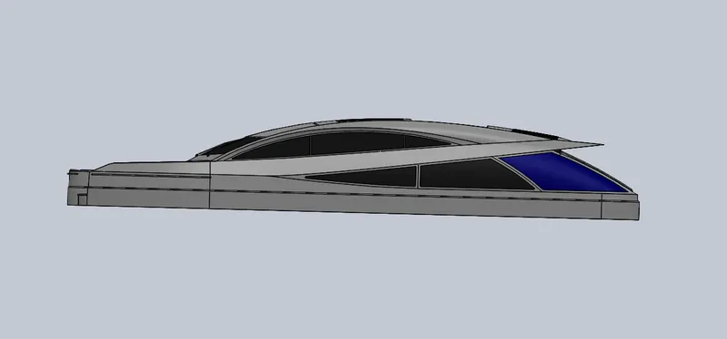
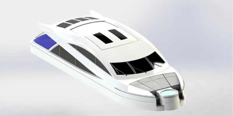
Superstructure - Isometric view
Tools and feature used:
|
|
|
|
|
|
|
|
|
|
|
|
|
|
|
|
|
|
|
|
|
|
|
|
|
|
|
|
8) Radar_Mast:
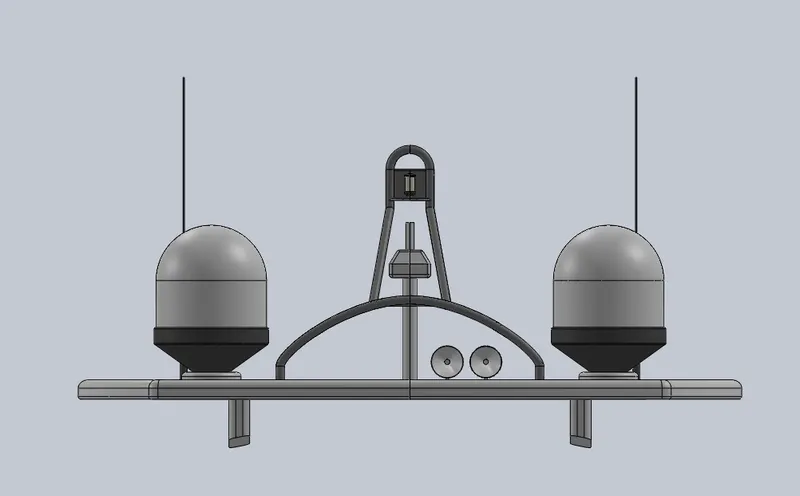 Radar_Mast- Front view Radar_Mast- Front view |
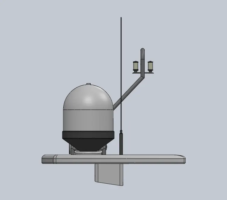 Radar_Mast- Side view Radar_Mast- Side view |
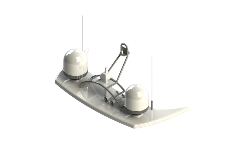
Radar_Mast - Isometric view
Tools and feature used:
|
|
|
|
|
|
|
|
|
|
|
|
II) Assembly of Yacht:
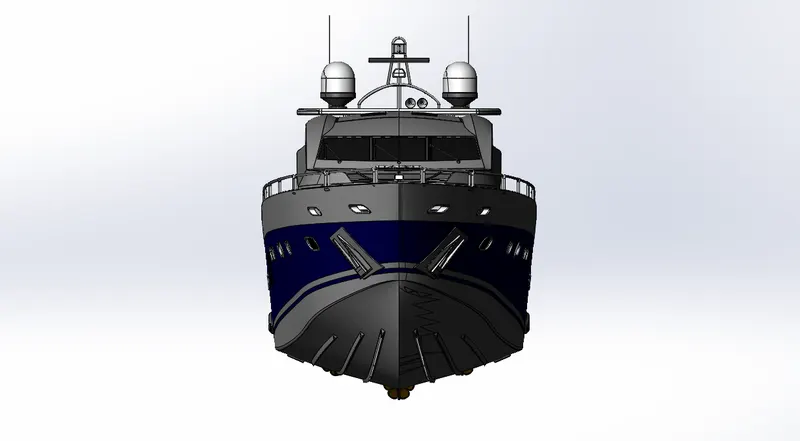
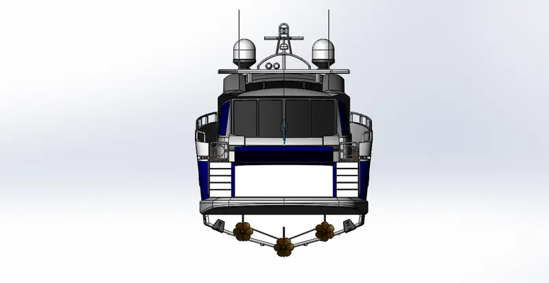
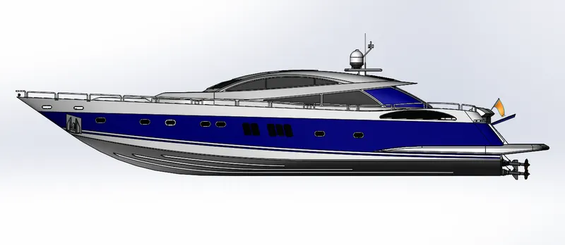
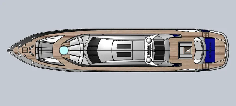
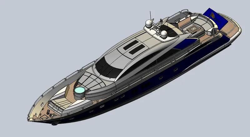
The yacht assembly is done in the assembly environment.
All the parts which are made previously are loaded in the environment and placed at their respective positions with the help of different kind of mates with suitable references for each mates such as planes or faces.
A) Front view of assembly
B) Back view of Assembly
C) Side view of Assembly
D) Top view of Assembly
E) Isometric view of Assembly
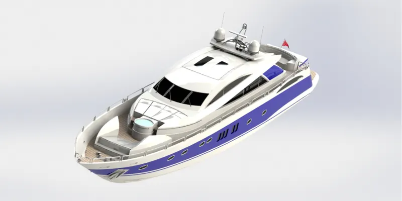
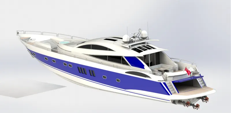
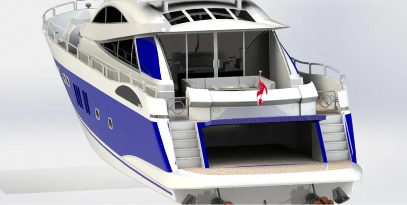
III) Rendered images of Yacht
A)
B)
C)
CONCLUSION:
In this project, each part is designed and modeled individually. All the parts are inserted into the assembly environment and the Yacht is assembled.