Photo Realistic Rendering
Assembly of Chopper model
OBJECTIVE:
- Design the individual part of American Chopper using Solid works.
- Assembling of all the individual parts of the Chopper by use of mates to constrain the Degrees of Freedom of various parts.
- Set up the suitable environment and adding the decals & Additional lights & cameras to render the Chopper model by using Photo View 360.
ITRODUCTION:
Solid works: Solid works is modeling software published by Dassault System Company. This software is mainly used to create 3D model using 2D sketch. It also has the option to specify the material and look for the model which we create. It has other Add in features like photoview360 which helps in rendering of final model to make it look photo realistic. In this project we learnt about detailed design of American chopper parts and assembling them and rendering the final chopper after assembly.
Chopper: The Chopper, It has come to represent a particular style of modified motor cycle with powerful engine, extended front end and lowered rear suspension. The basic parts in the Chopper are Engine, Chassis, Front and rear wheel, Front and rear fender, Front fork, Oil tank, Gas tank, Transmission belt, Kick stand, Front fork and Chain part.
DESIGN METHODOLOGY:
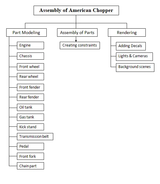
DESCRIPTION:
I) Part Modeling:
Explanation of tools and features used while designing:
Tools used:
1. Sketch: Used to create a 2D sketch by using sketch tools.
2. Line: Used to draw lines. Different types of lines are mentioned below.
-
- Centre/Construction line
- Midpoint line
3. Circle: Used to draw circles. Different types of circles are mentioned below.
-
- Centre point circle
- Perimeter circle
4. Arc: Used to draw arc. There are 3 types of arc
-
- Centre point arc
- Tangent arc
- 3 point arc
5. Rectangle: To create rectangles. Types of rectangles are mentioned below
-
- Centre rectangle
- Corner rectangle
- 3 point corner rectangle
- 3 point center rectangle
- Parallelogram
- Spline: It is a special type of sketch entity which is used to draw smooth curves through interpolation of points.
- Straight slot: To sketch a straight slot.
- Fillet: To create smooth or round edges at the intersection of two sketch entities
- Chamfer: It is used to cut a sharp edge/face usually at a 45° angle to the adjacent principal edge/face or a cut on the edge or corner of something that makes it slope slightly rather being perfectly square.
- Trim/Extend: Trims/Extends a sketch entity to be coincident to another.
- Convert entities: To convert selected model edges or curves into sketch segments
- Offset entities: To add sketch entities by offsetting faces, edges, curves at a specified distance.
- Intersection curve: To get an intersection curve obtained from projection of two curves.
- Mirror: To mirror entities about an axis.
- Dynamic mirror: Mirrors entities dynamically. It creates mirrored entities at a same time while drawing.
- Sketch pattern: To create a pattern of sketch entities along a linear/circular reference. Types of patterns are mentioned below
-
- Centre point circle
- Perimeter circle
-
- Smart dimensions: Used to add or edit dimensions of sketches.
Features used:
- Extruded Boss/Base: Used to create 3D solid from 2D sketch. It extrudes a selected sketch in one or two direction to create a solid feature.
- Swept Boss/Base: Used to create a solid body along the profile path.
- Revolved Boss/Base: Revolves a selected sketch around an axis to create a solid body.
- Extruded cut: Cuts a solid model by extruding a sketched profile in one or two direction using 2D sketch.
- Revolved cut: Cuts a solid model by revolving a sketched profile around an axis.
- Lofted cut: Cuts a solid model by removing material between two or more profiles.
- Reference plane: It is used to construct a plane when the existed planes are not suitable to create sketches/features.
- Mirror: To mirror the features about a plane.
- Combine: To combine two or more solid bodies.
- Dome: To create dome surfaces on flat surfaces.
- Split: To create multiple bodies from a single body.
- Pattern: To create a pattern of features, faces and bodies in one or two direction along a reference path. Types of patterns are mentioned below
-
- Linear pattern: To create a pattern of feature/body along a linear reference.
- Circular pattern: To create a pattern of feature/body along a circular reference.
- Curve driven pattern
- Sketch driven pattern
- Variable pattern
-
- Chamfer: To convert sharp edges into bevel edges.
- Composite curve: Used to obtain combined composite curve from two or more curves.
- Projected curve: It is a tool use to form 3D curves from two 2D curves from two different planes.
- Smart dimensions: Used to add or edit dimensions of sketches.
Designing of all parts and components are as follows:
1) Engine
Engine is a powerhouse of vehicle. An engine is a machine designed to convert one form of energy into mechanical energy. And this energy is transferred to rear wheel through chain and sprocket.
The modeling starts with the gear housing and motor housing. This housing is made with the use of basic sketch tools and extrude feature. Then cylinder is made of polygon shape and cuts are made to show fins for cooling. The cylinder is then mirrored. After mirror is done the pipes are made which connects the cylinder using sweep feature. Then the exhaust is made by using projected curve and sweep feature.
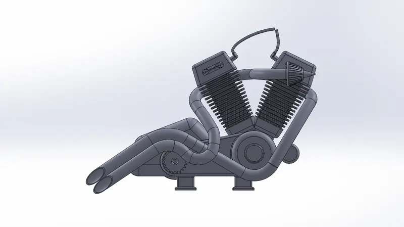 Engine- Front view Engine- Front view |
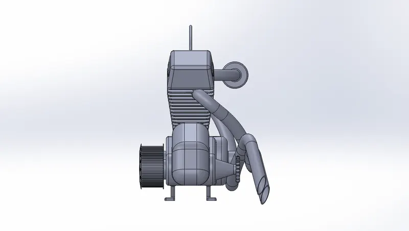 Engine- Side view Engine- Side view |
|
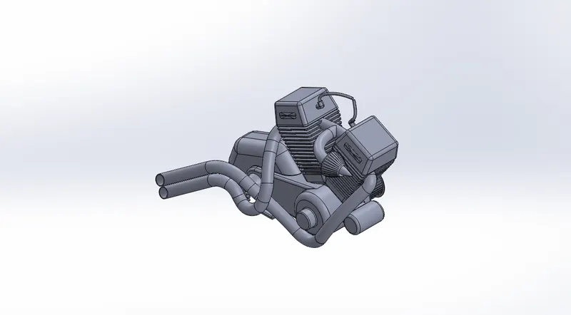 Engine- Isometric view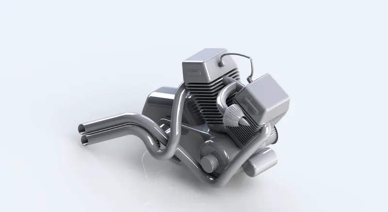
Engine- Rendered image
Tools and feature used:
Sketch picture: Insert the picture for reference.
|
|
|
|
|
|
|
|
|
|
|
|
|
|
|
|
|
|
|
|
|
2) Chassis
A motorcycle’s chassis/frame forms its skeleton. Chassis is the most vital part of the vehicle. The strength of the bike is decided by the chassis. It supports the engine, provides a location for the steering and rear suspension and supports the rider and any passenger. And also fuel tank and battery are attached to the frame. The steering head tube is located at the front of the chassis/frame that holds the pivoting front fork, while at the rear there is a pivot point for the suspension motion.
Modelling starts from the tubes of chassis. Front side tubes and back side tubes are modeled using projected curve. Then the back side plate is made. Similarly all tubes are created then the bottom plates are extruded from one tube to opposite tube. After all this done fillet, chamfer, mirror etc are done for creating final chassis model.
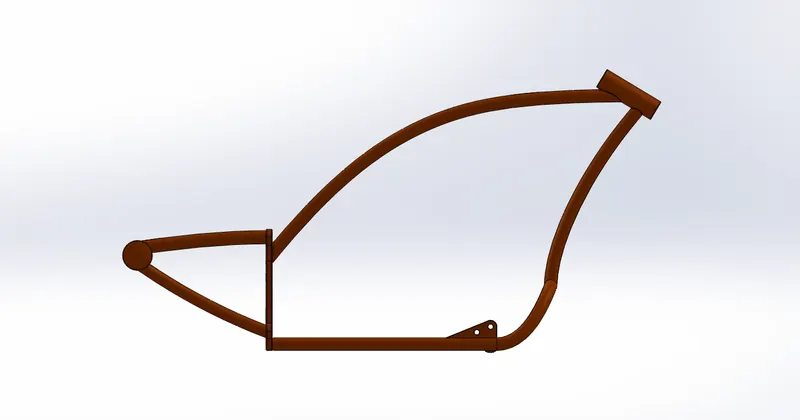 Chassis- Front view Chassis- Front view |
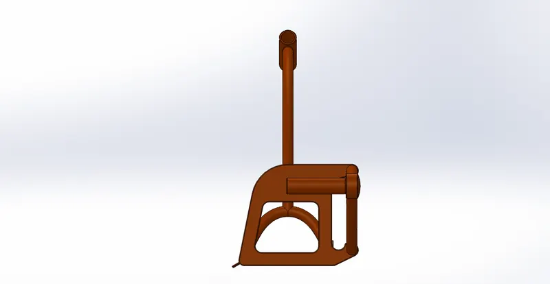 Chassis- Side view Chassis- Side view |
|
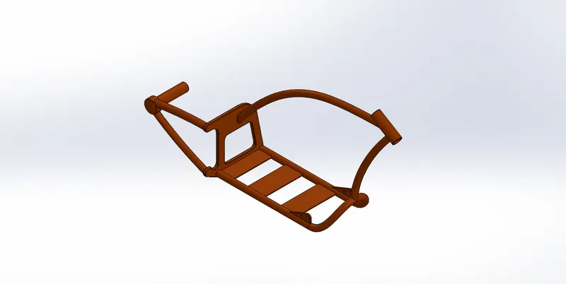 Chassis- Isometric view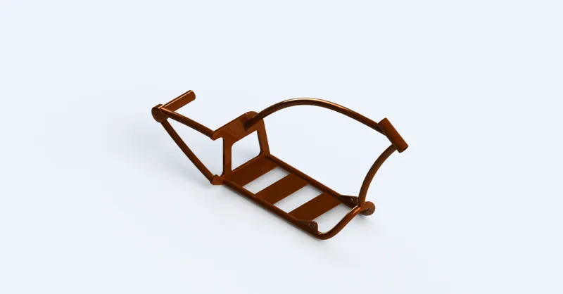
Chassis- Rendered image
Tools and feature used:
Sketch picture: Insert the picture for reference.
|
|
|
|
|
|
|
|
|
|
|
|
|
|
|
3) Front and rear wheel
A wheel is a circular part attached to rim and filled with air. And it is made up of a hard and durable material whose center has been bored a hole through which an axle bearing is placed, about which the wheel rotates when torque is applied to the wheel about its axis. Brake pad and caliper are attached to the front and rear wheel. Chain sprocket is attached to rear wheel only. In this project front wheel is smaller than the rear wheel.
The front and rear both wheels are made similarly. First the rim and hub is made by using revolve feature and then the webbing of rim is done. After that the brake pad, caliper and sprocket are made by using basic sketch tools and features.
Front wheel images:
|
|
|
|
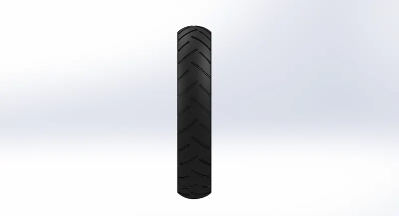 Front wheel- Front view
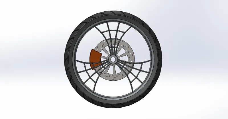 Front wheel- Side view
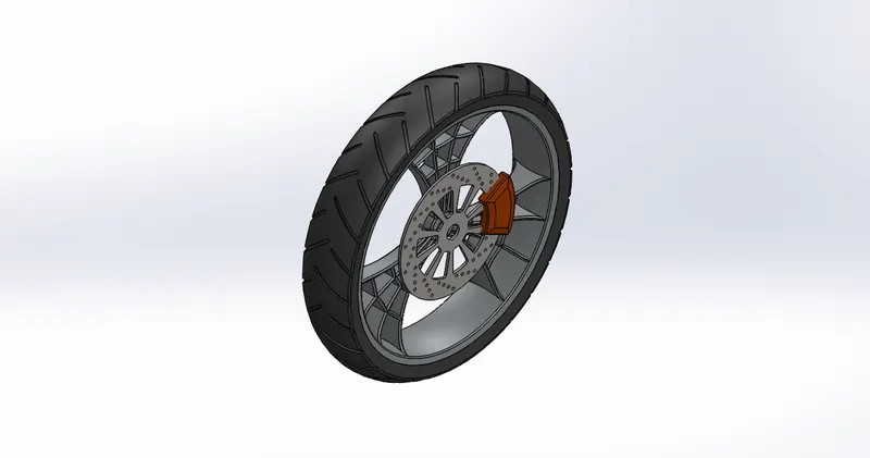 Front wheel- Isometric view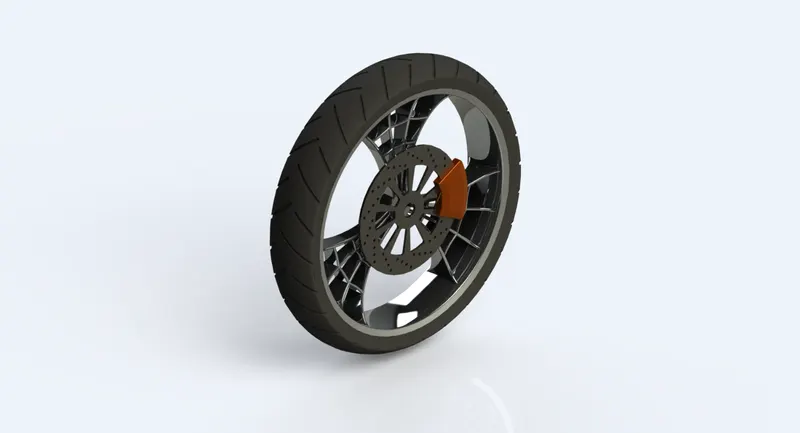
Front wheel- Rendered image
Rear wheel images:
|
|
|
|
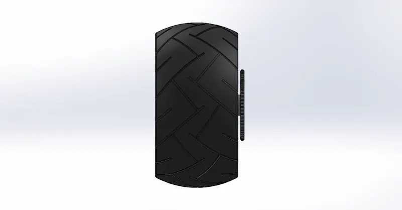 Rear wheel- Front view
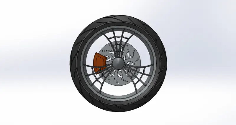 Rear wheel- Side view
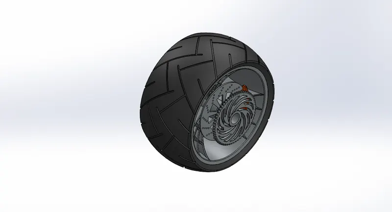 Rear wheel- Isometric view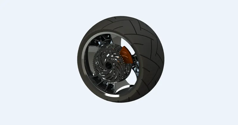
Rear wheel- Rendered
Tools and feature used:
Sketch: To create required sketches.
|
|
|
|
|
|
|
|
|
|
|
|
|
|
|
4) Front and rear fender
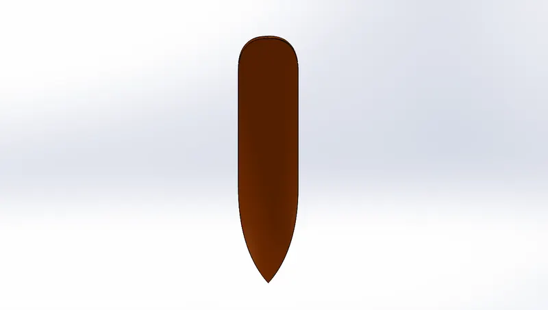
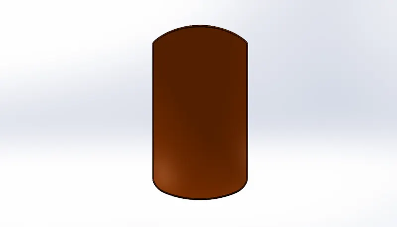
Front fender is located over the front wheel and rear fender is located over on rear wheel. Fenders are used to protect the rider and pillion/baggage from the mud, debris, water etc. which are thrown by the tires while riding.
Both the front and rear fender are basically modeled with similar method. Firstly, the sketch is revolved and then it is splitted or surface trimmed to get the required size. Then other features like fillet are used to avoid the sharp edges. Lastly shell is performed to get convex hollow part. Only the shape and size vary in both the fenders.
Front fender images:
|
Front fender- Front view |
|
|
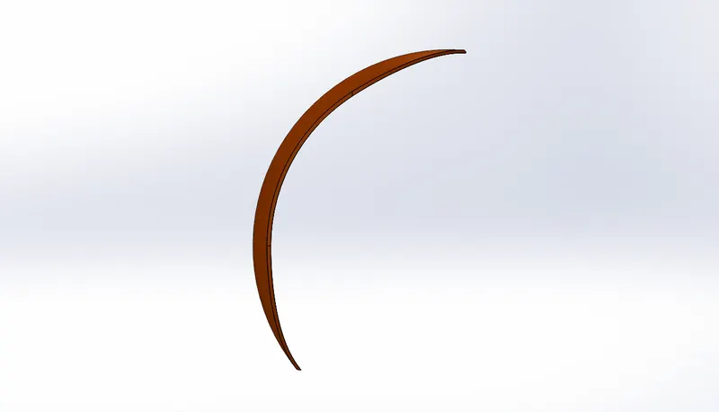 Front fender- Side view
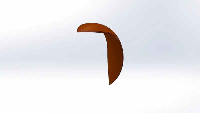 Front fender- Isometric view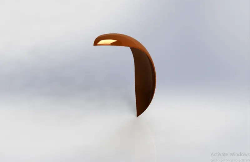
Front fender- Rendered image
Rear fender images:
|
Rear fender- Front view |
|
|
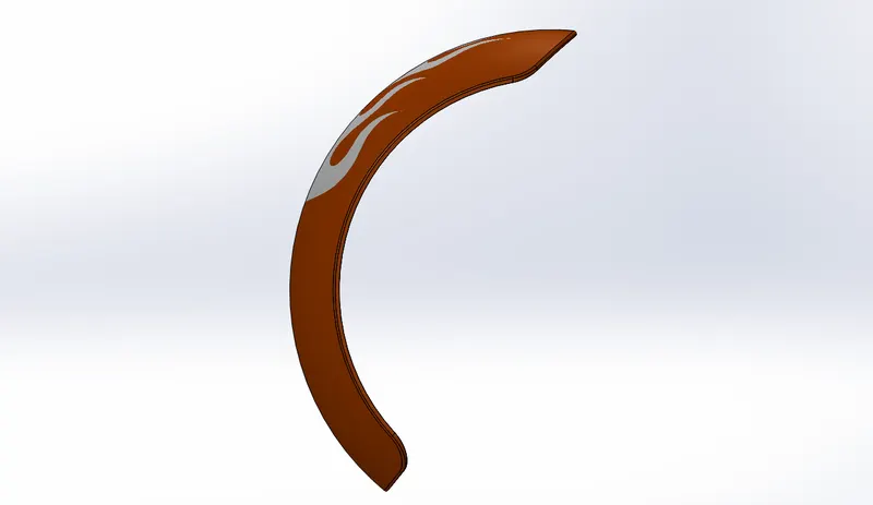 Rear fender- Side view
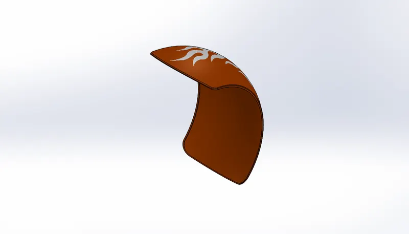 Rear fender- Isometric view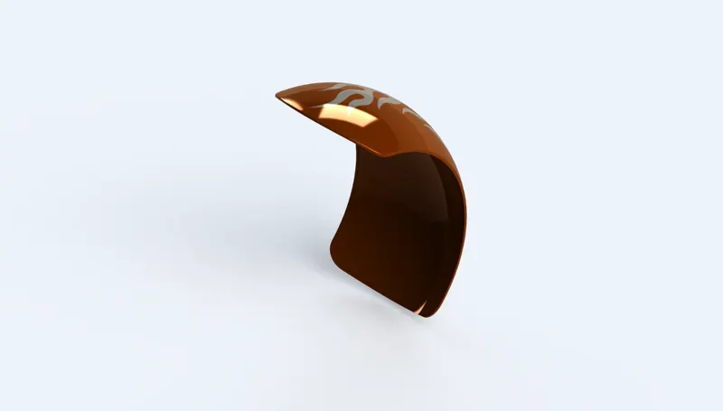
Rear fender- Rendered image
Tools and feature used:
Sketch: To create required sketches.
|
|
|
|
|
|
|
5) Front fork
Fork holds the front wheel and is fixed to the chassis. The forks can be most easily understood as simply large hydraulic shock absorbers with internal coil springs. They allow the front wheel to react to imperfections in the road while isolating the rest of motorcycle from that motion. American choppers have long forks and at extreme angles.
First create a model of fixed rod by using revolved feature. Then model the half of triple tree by extruding and then patterning the counterpart. Then part of the axle is extrude and revolved to model the light. After this the handle is made by sweeping the circular sketch along the projected curve. The grip, brake and brake wire are model similarly with the reference of projected curve. Then mirror it and combine. Then add some extra features like dome, fillet etc...
|
Front fork- Front view |
Front fork- Side view |
Front fork- Isometric view |
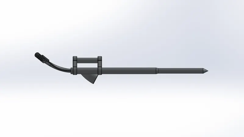
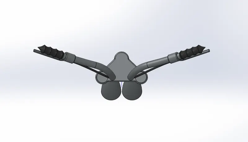
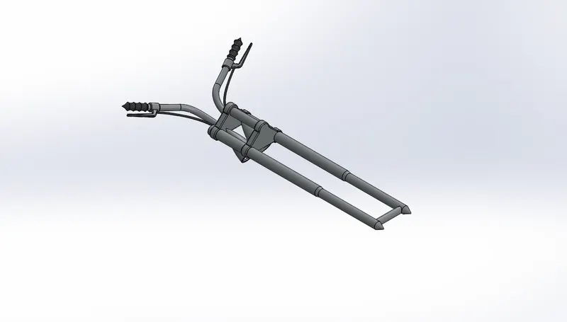
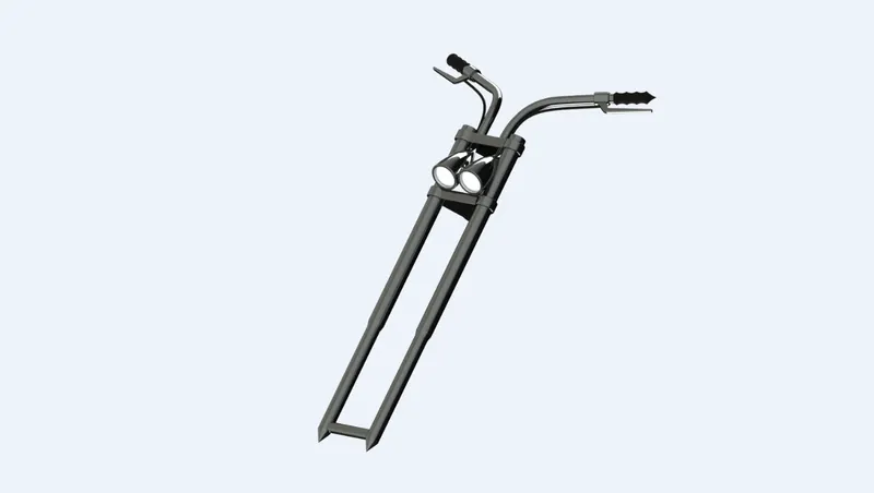
Front fork- Rendered image
Tools and feature used:
Sketch: To create required sketches.
|
|
|
|
|
|
|
|
|
|
|
|
|
|
|
|
|
6) Gas tank
Gas tank is the fuel tank which stores fuel and it is in complicated shape. And it is a safe container for flammable fluids. As it is at top of the bike it is made stylish with great aesthetic look.
The start of the modeling is from the basic shape of gas tank which is created using surface sweep and other tools. Then the end of gas tank which is bent in triangular shape is made using projected curve and surface loft. Similarly, the side surface is created using projected curve and surface loft and the seat is created by extruding. Then the bottom surface is created and closed tank is made. Then the cut-out is made for the tube of chassis. Finally the fillet is created to avoid sharp curves and then shelled to create to hollow part inside.
|
Gas tank- Front view |
Gas tank- Side view |
Gas tank- Isometric view |
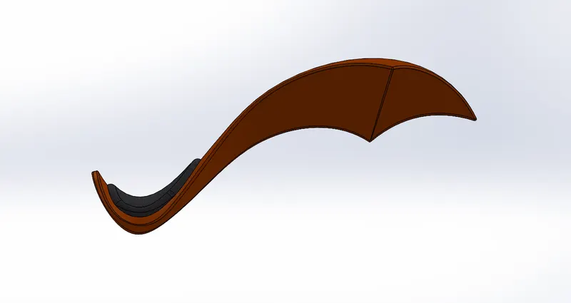
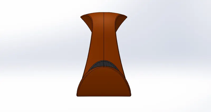
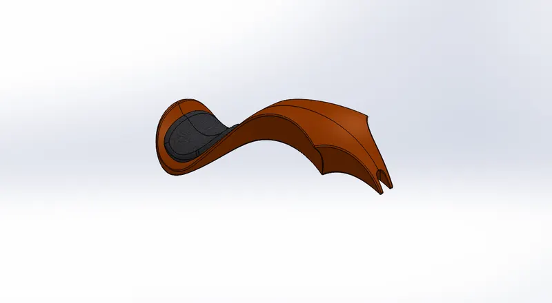
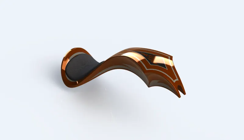
Gas tank_ Rendered image
Tools and feature used:
Sketch picture: Insert the picture for reference.
|
|
|
|
|
|
|
|
|
|
|
|
|
|
|
7) Oil tank
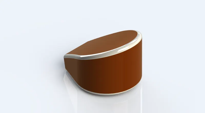
The oil tank is just a hollow box, which is used to store the oil required. The stored oil then used to engine for smooth working.
Modelling of oil tank is simple. Basic process to design is sketching the required shape, and then makes a solid body by extruding, trimming unwanted and knitting. After solid shape is formed use shell feature to make it hollow inside. Fillet the edges for removing corners.
|
Oil tank- Front view |
Oil tank- Side view |
Oil tank- Isometric view |
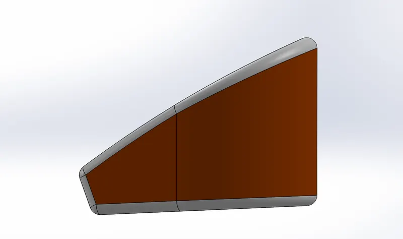
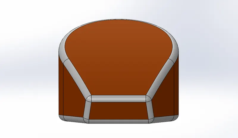
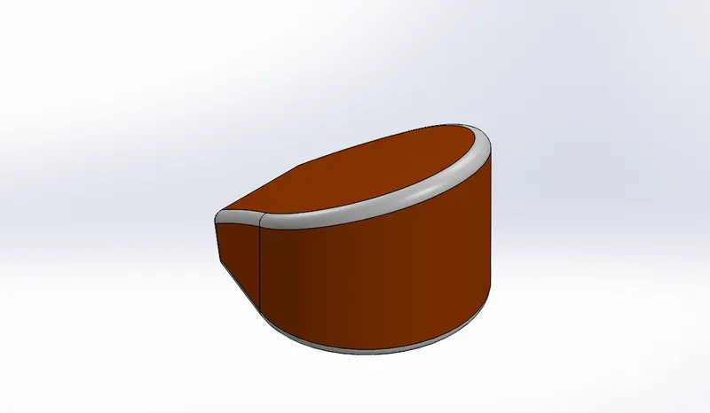
Oil tank- Rendered
Tools and feature used:
Sketch: To create required sketches.
|
|
|
|
|
|
|
|
8) Pedal
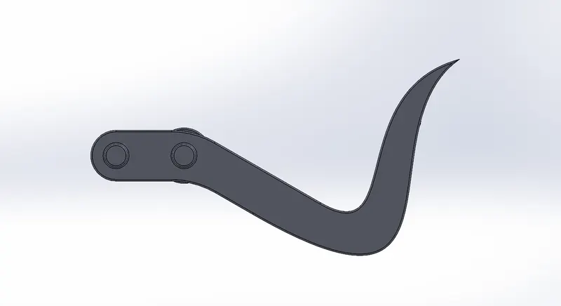
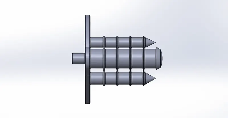
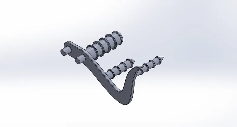
Pedal is the external part attached to the chassis. The pedal is used to place the leg on top of that to give comfort to the rider. It also gives comfort place to rest his (Rider) foot while applying pressure to brake and while changing the gear in manual bikes.
First draw the basic shape of pedal in sketch and then extrude it. Then sketch the circles for the part where rider rests his foot and extrude it. Use revolve, chamfer and fillet for aesthetic look and smoothing of part.
|
Pedal- Front view |
Oil tank- Side view |
Oil tank- Isometric view |
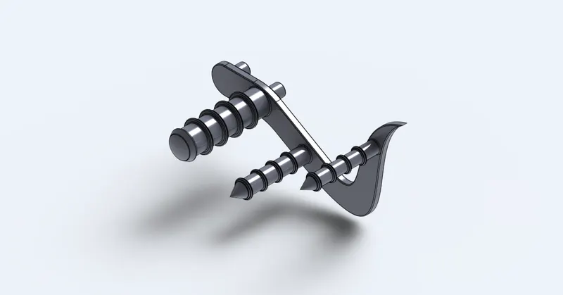
Pedal-Rendered image
Tools and feature used:
Sketch: To create required sketches.
|
|
|
|
|
|
|
|
|
|
|
|
9)Transmission belt
Transmission belt in bikes are generally used to offer noise-free, smooth transmission for long distance riding. Since comfort, smoothness and less maintenance is more important here as compared to performance or fuel efficiency, the belt drive system lends itself well to the application. It is a loop of flexible material running over the pulleys or sprocket to link two rotating shafts for transmission of power from engine to gearbox.
Two circles are sketched apart and then are joined by the line tangentially. The inner parts of circles are trimmed and the whole sketch is extruded. Fillet the borders for smooth transmission.
|
Transmission belt- Front view |
Transmission belt- Side view |
Transmission belt- Isometric view |
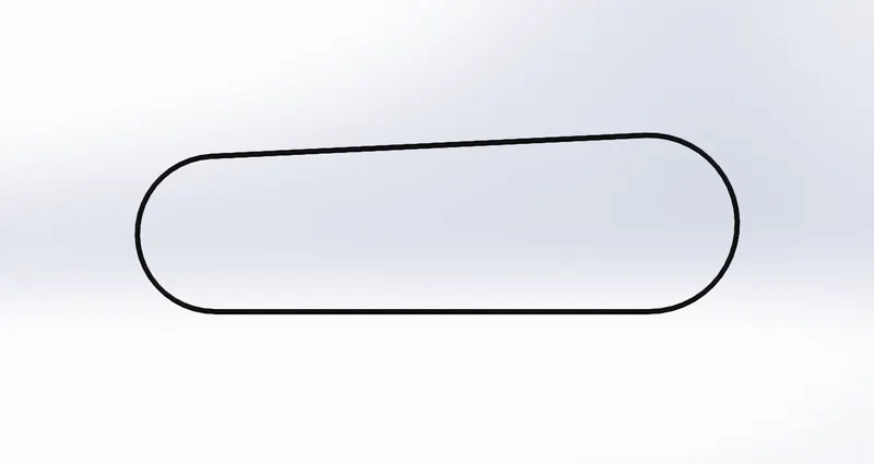
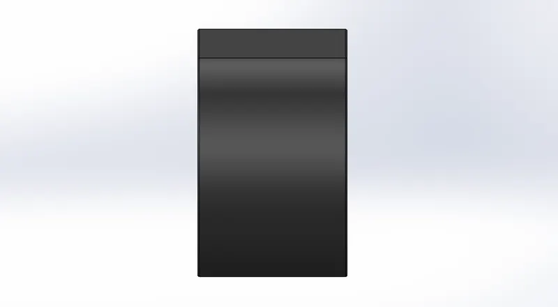
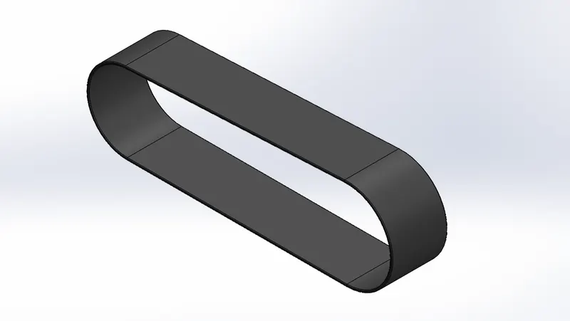
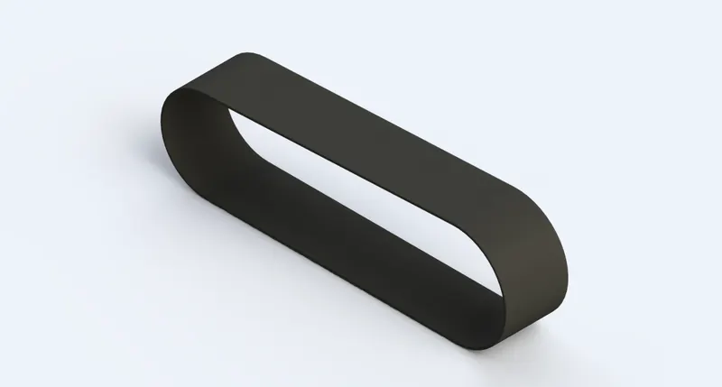
Transmission belt-Rendered image
Tools and feature used:
Sketch: To create required sketches.
|
|
|
|
|
10) Chain part
Chain is a type of transmission system that is used to transmit a power from the engine to the rear wheel. The sprocket is used to transmit the power to the chain. The sprocket is connected with the shaft with the help of key.
First the pin/roller and plate should be made and then the path or profile should be made over which the roller and plate link will be patterned the profile is made by various curvature. So as the curvature varies the pattern feature is repeated until the end of the link matches with the start. After using pattern feature check whether the links are properly matched at the end, if not, copy and constrain the link between last and first link.
|
Chain- Front view |
Chain- Side view |
Chain- Isometric view |
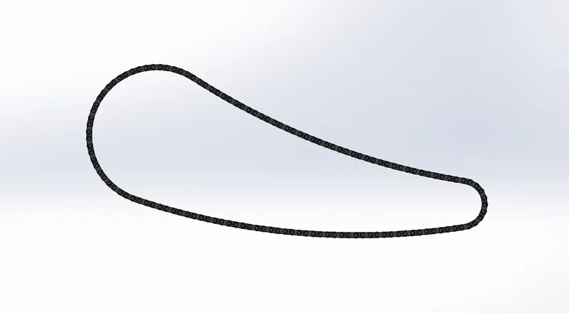
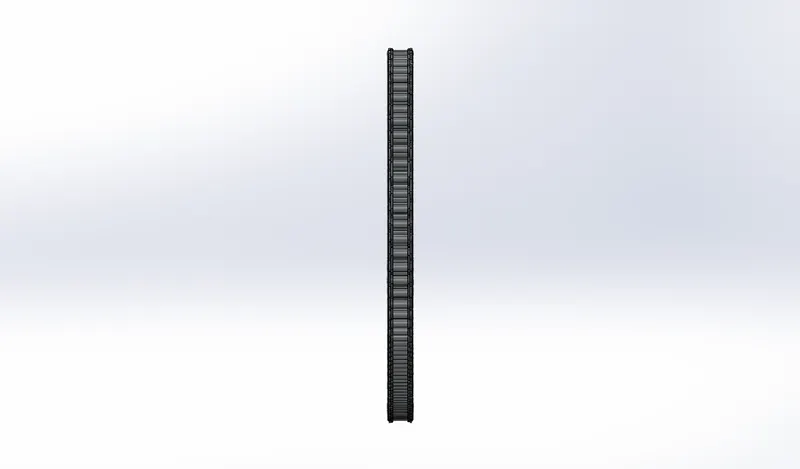
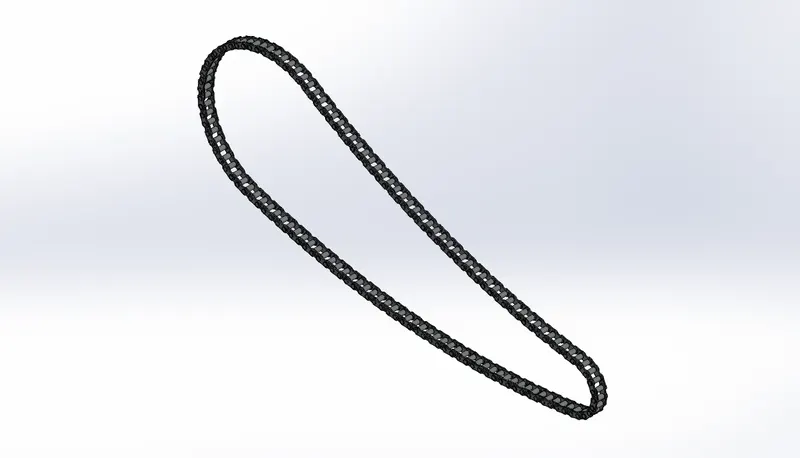
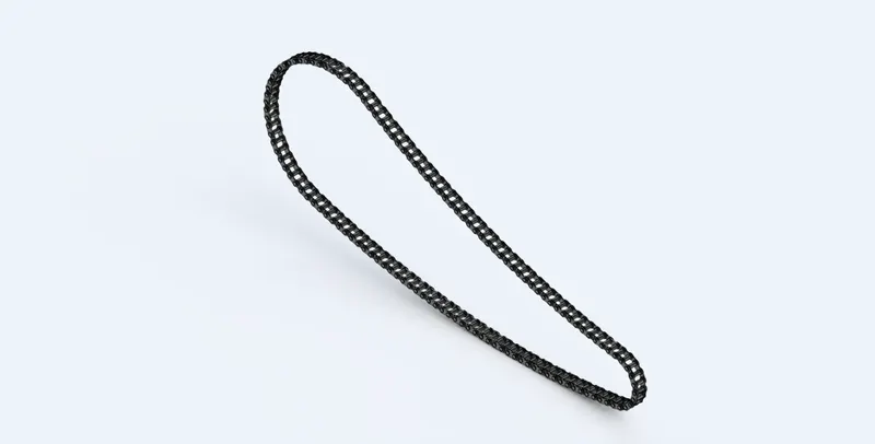
Chain-Rendered image
Tools and feature used:
Sketch: To create required sketches.
|
|
|
|
|
|
|
|
|
|
|
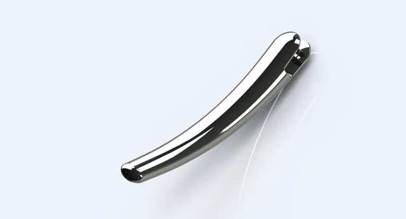
11) Kick stand
The kickstand is usually a simple metallic part that touches the ground and allows the bike to stand.
Modeling of the kickstand is can be done by creating the 2D sketch. Use basic features like extrude boss, extrude cut, loft, trim, dome and fillet to create model. Kickstand model consists of lofted profiles with dome at one end.
|
Kick stand- Front view |
Kick stand- Side view |
Kick stand- Isometric view |
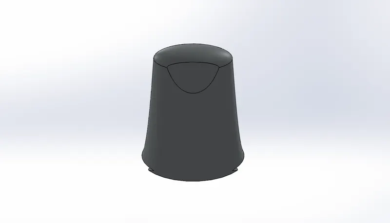
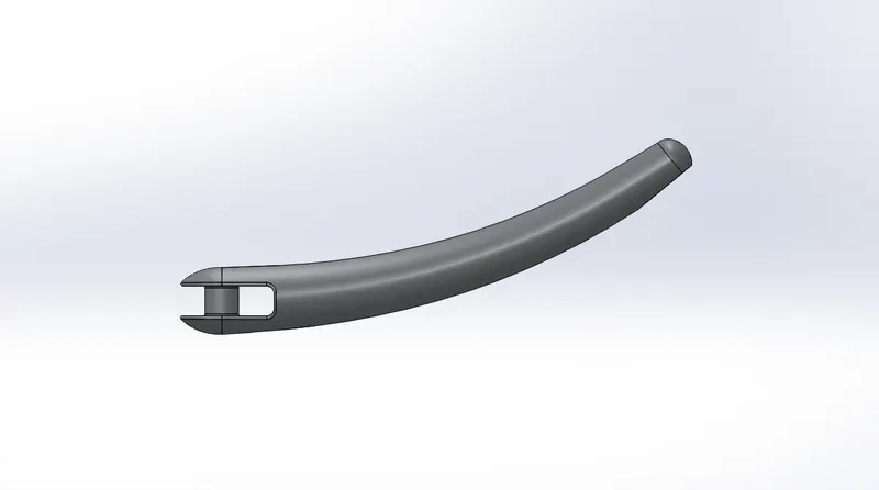
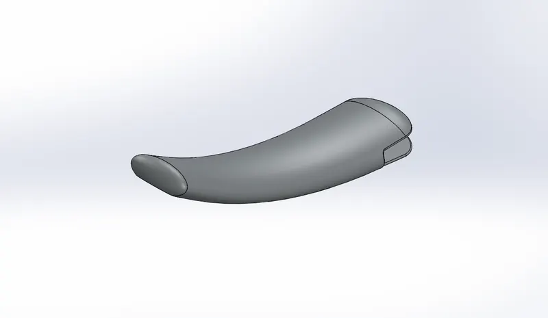
Kick stand- Rendered image
II) Assembly of Chapper
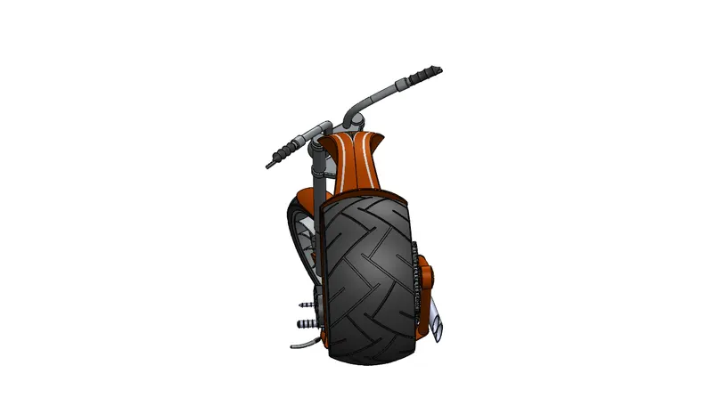
First step of assembly is done by adding all the created components nto the assembly space. Then by making vital part fixed in the space, in this case the chassis is going to be fixed. Once the chassis is fixed then all the other parts are matted together using different types of mate like coincident, concentric, distance, collinear, width etc… Once all parts are matted and assembly is done, rendering can be started.
III) Rendering
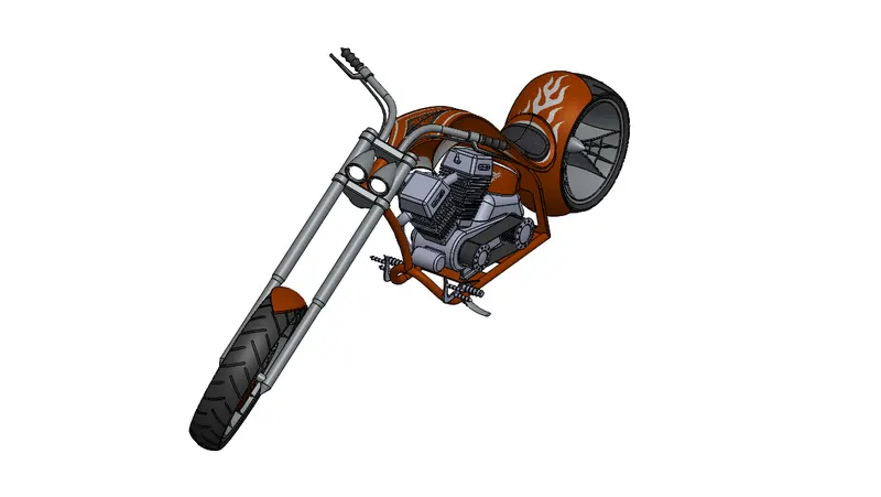
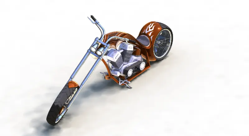
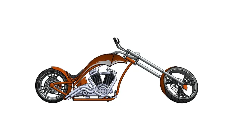
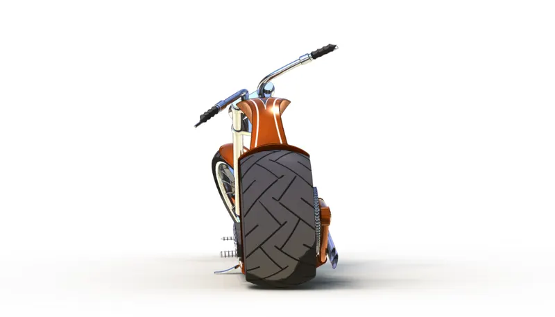
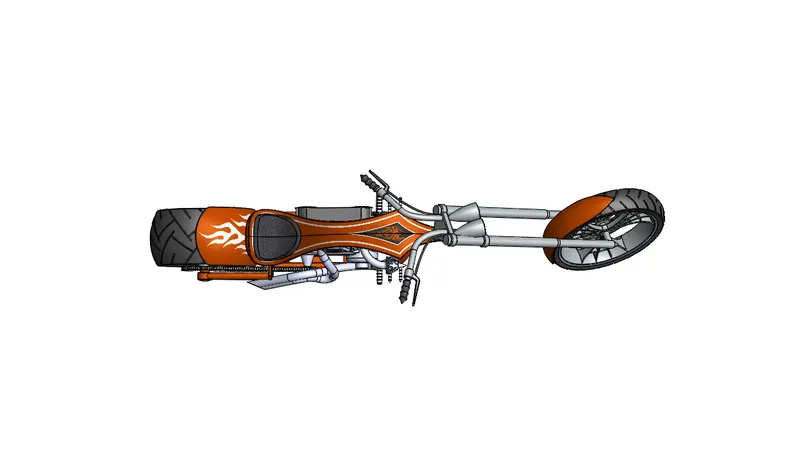
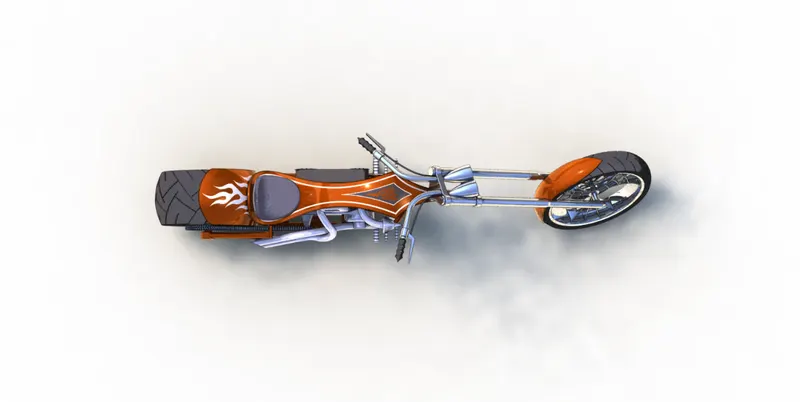
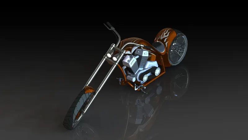
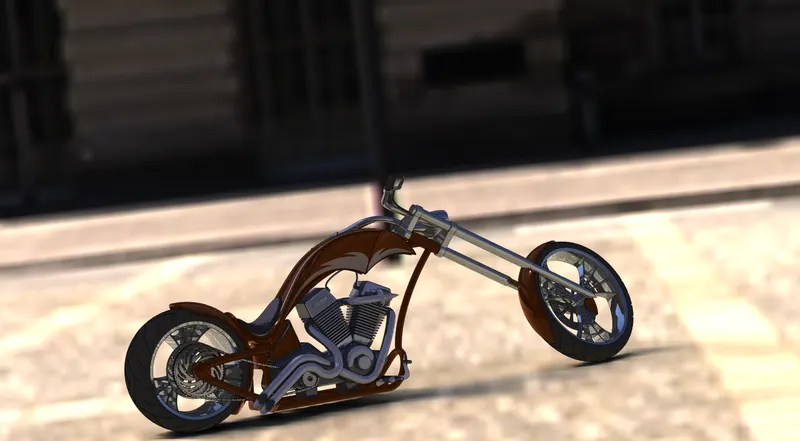
Photoview 360 or solidworks visualize is use for rendering the models. Rendering is done to make the object realistic. Adding decals, scenes, Environment, Lighting setup, appearance of any material etc. are rendering process. In this project, to render the bike the decals are added with daytime environment to obtain reflections of the parts. Different material are applied to the each object to give realistic appearance. Then the camera setup is done which shows the view from angle set in the camera. Add decals to the rear fender and gas tank and proper mapping is carried out. Check for appropriate scenes and proper light set up to make the chopper realistic in final rendering.
Assembly and rendering images:
1) Camera view
Assembly_Camera view
Rendered_Camera view
2) Front view
Assembly_Front view
Rendered_Front view
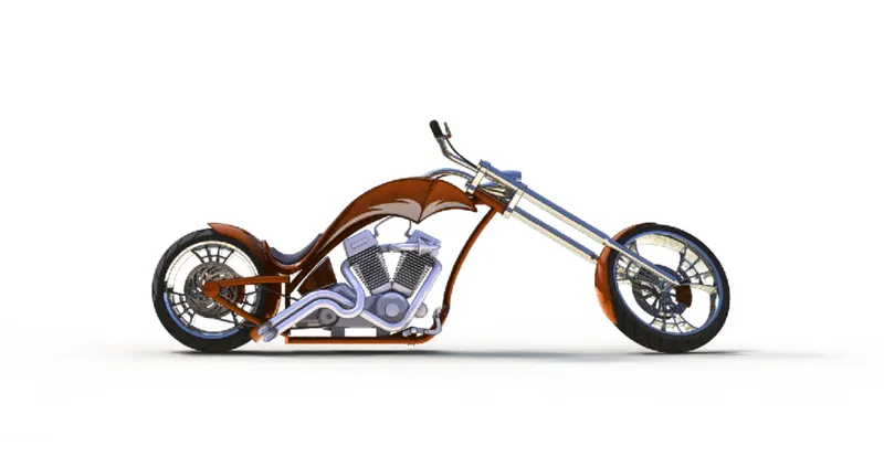
3) Side view
Assembly_Side view
Rendered_Side view
4) Isometric view
Assembly_Isometric view
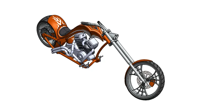
Rendered_Isometric view
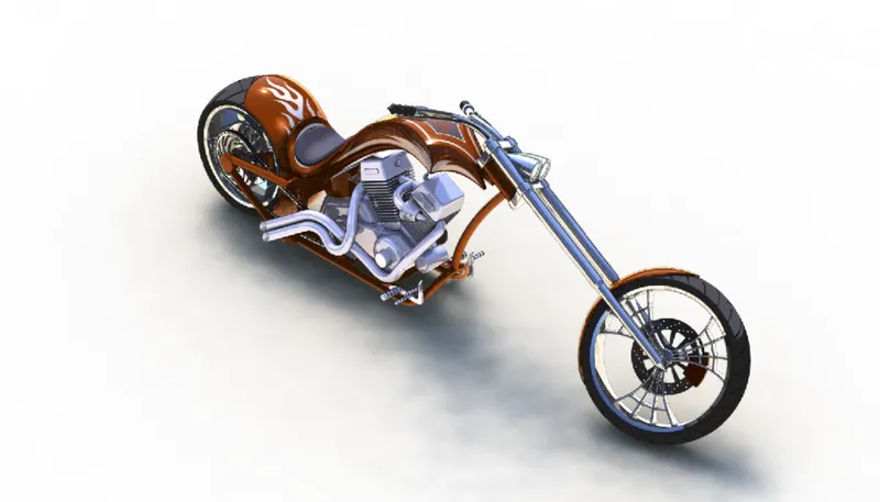
5) Top view
Assembly_Top view
Rendered_Top view
Rendered with Environment
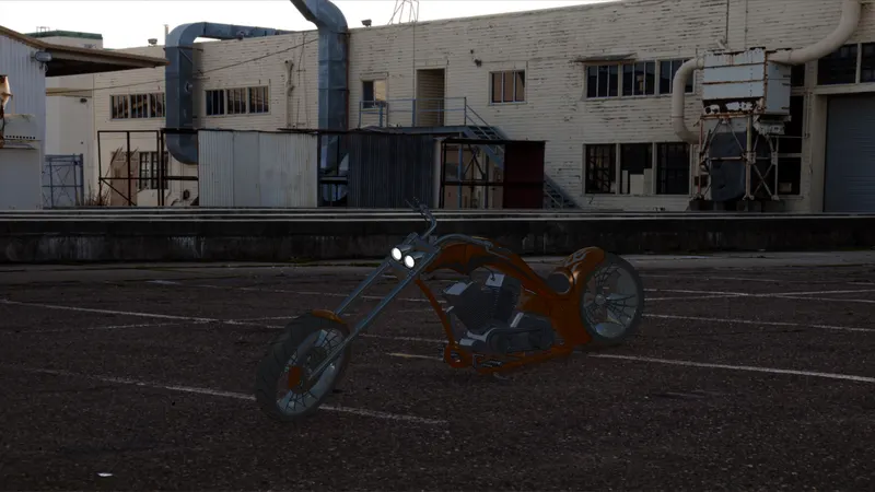
Rendered_Reflective Floor Black Scene
Rendered_Courtyard
Tools and feature used:
- Decals: Graphics or designs used on chopper bodies.
- Light and Camera: To adjust lighting and camera angles.
- Render Preview: To preview the final render before rendering.
- Render: To render in required quality and sizes.
CONCLUSION
In this project, each part is designed and modeled individually. All the parts are inserted into the assembly environment and assembled to create a model of American chopper. The realistic image was rendered with the use of the Photoview 360 and solidworks visualize.