Roof challenge
MODELING OF AUTOMOBILE ROOF AND ASSEMBLLY
Aim:
To design of car roof by using of NX CAD software and chech weather heat distortion and snow load condition.
Introduction:
An automobile roof or car top is the portion of an automobile that sits above the passenger compartment, protecting the vehicle occupants from sun, wind, rain, and other external elements. Because the earliest automobiles were designed in an era of horse drawn carriages, early automobile roofs used similar materials and designs
Roof variations :
1. convertible roofs
2. Hardtops
3. sunroofs
4. T- Tops
5. Targa Tops
6. Vinyl roofs
Design Approach
Main Parts of Roof :
1. Outer panel
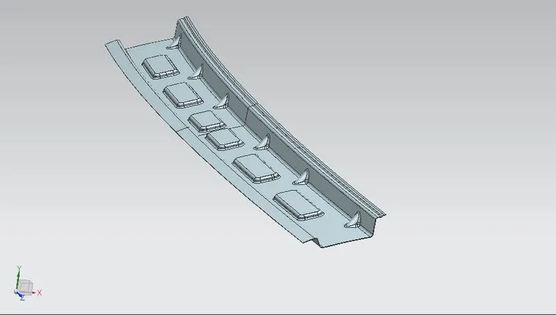
2. Front roof rail
3. Rear roof rail
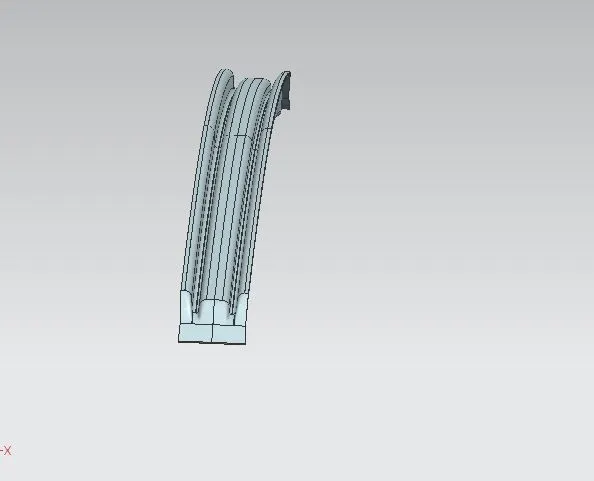
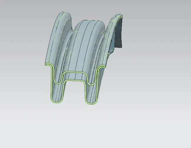
4. Center roof rail
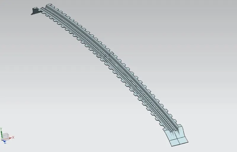
5. Bow roofs
Front roof rail :
Center roof rail :
Bow roofs :
Rear roof rail :
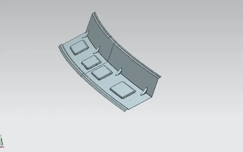
Heat Distortion
Bow–roof prediction Formula
W = [1.73 x 10^(-3) x L] + [1.85 x 10^(-8) x (R^2)/t] + [ 1.10x10^(-3) x l] - 2.68
Judgement Condition : OK< 2.7> 3.1
Where
L = Roof Length in X-Direction[mm](Roof dimension in 0-Y)
R = Roof curvature
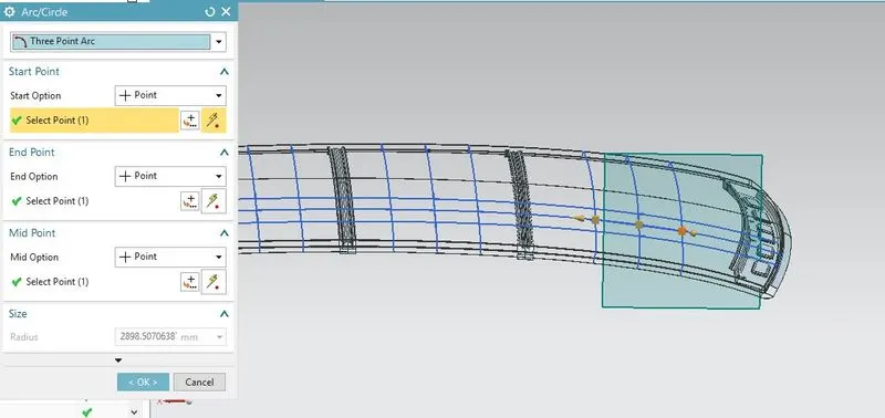
R = 2(Rx*Ry)/(Rx+Ry)
Rx = X curvature
Ry = Y curvature
t = Roof plate thickness [mm]
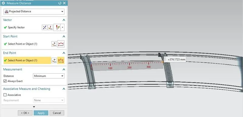
l = Bow Roof Span [mm]
Rx calculation :
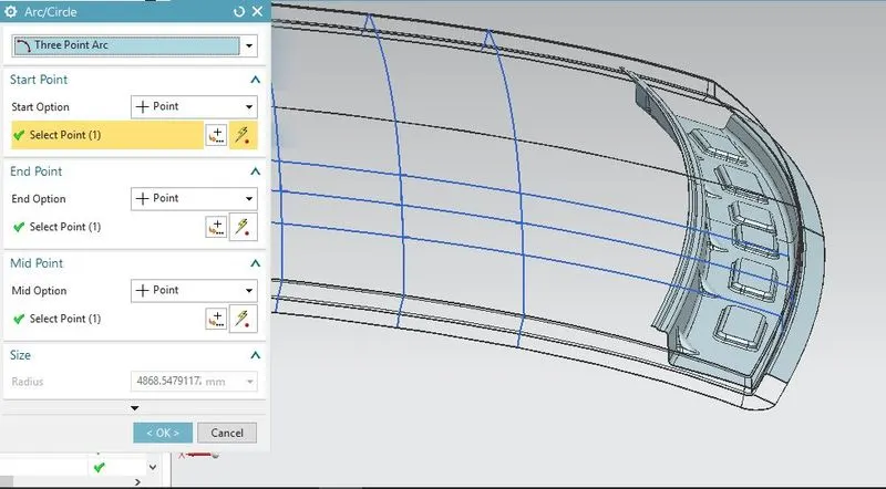
Ry calculation :
Bow Roof Span :
Roof Length in X-Direction :
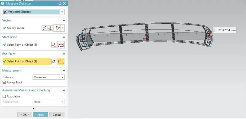
Sample Calculation :
R = 2(Rx*Ry)/(Rx+Ry)
R = 2(5715.76*2898.51)/(5715.76+2898.51)
R = 3846.452
W = [1.73 x 10^(-3) x L] + [1.85 x 10^(-8) x (R^2)/t] + [ 1.10x10^(-3) x l] - 2.68
W = [1.73 x 10^(-3) x 2033.28] + [1.85 x 10^(-8) x (3846.452^2)/0.75] + [ 1.10x10^(-3) x 492.26] - 2.68
W = 3.5176 + .36495 + 0.5415 - 2.68
w = 1.74 Condition : OK< 2.7> 3.1
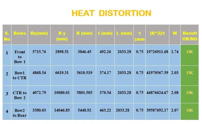
In refered above table position Bow roofs condition all satisfied
Snow load prediction
Qr = [Iy x t2] / [α x s x [(Rx + Ry)/2]2 x 10-8]
Where
α = My x Lx2 x 10-12 , My = Y(Ly-Y)
Judgement condition = Qr ≥ 3.1
250 ≤ s ≤ 380
t = Roof plate thickness [mm]
Ly = Distance between the front and rear roof Rails on the Vehicle along with 0Y[mm]
Length of Roof panel with the center point between Roof rail Front /Rear as the front and rear reference point.
Lx = Distance between the Left and Right end of the roof on the Roof BOW [mm]
Width of the roof panel exposed on the surface.
Y = Distance front Front Roof Rail to Roof BOW[mm]
s = Distance for which Roof BOW bears divided load [mm]
s = L1/2 + L2/2
Iy = Geometrical moment of inertia of Roof BOW (Y cross-section )[mm4]
Rx = Lateral direction curvature radius of roof panel Y cross-section on Roof BOW [mm]
Roof panel curvature Radius of the Length Lx in Front view
Ry = Longitudinal Direction curvature radius of the Roof panel X cross-section on Roof BOW [mm]
Roof panel X curvature radius of length s in Side view
Rx calculation :
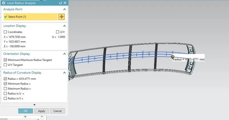
Ry calculation :
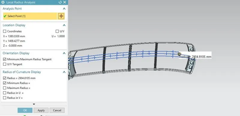
Lx calculation :
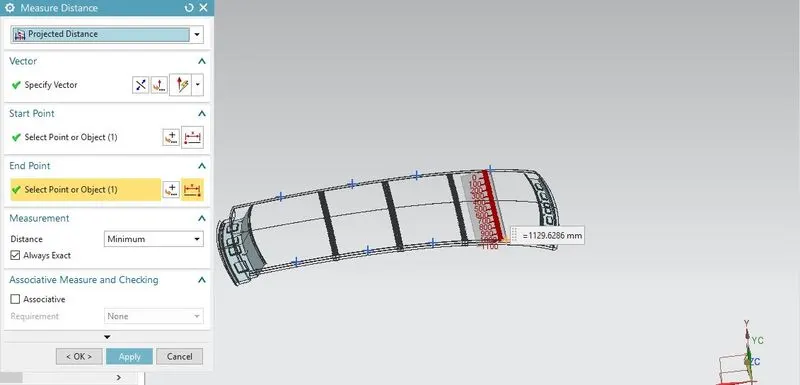
Ly calculation :
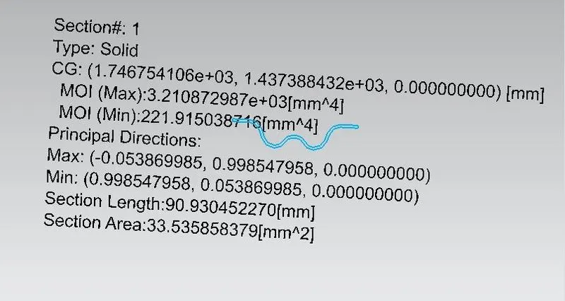
Moment of Inertia of Bow Roof 1:
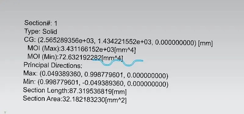
Moment of Inertia of Bow Roof 2:
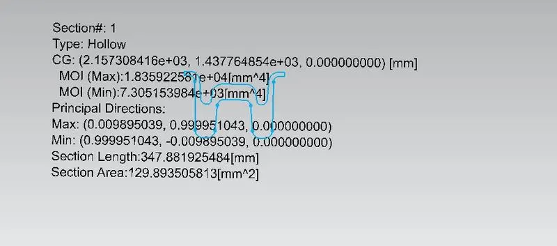
Moment of Inertia of center roof :
Moment of Inertia of Rear roof :
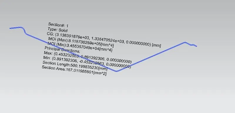
Sample Calculation :
My = Y(Ly-Y)
My = 566.51(2033.28-566.51)
My = 830937.0648
α = My x Lx2 x 10-12 , My = Y(Ly-Y)
α =830937.0648 x 1129.632 x 10-12
α = 1.060325068
Qr = [Iy x t2] / [α x s x [(Rx + Ry)/2]2 x 10-8]
Qr = [221.915 x 0.752] / [1.060325068 x 488.57 x [(4353.47 + 2904.10)/2]2 x 10-8]
Qr = 1.8299 condition = Qr ≥ 3.1
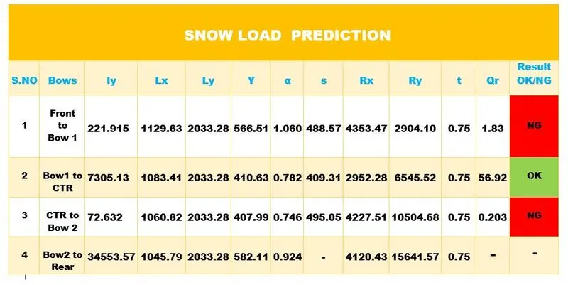
1. Refer above table only satisfied snow load condition on Bow1 to center roof
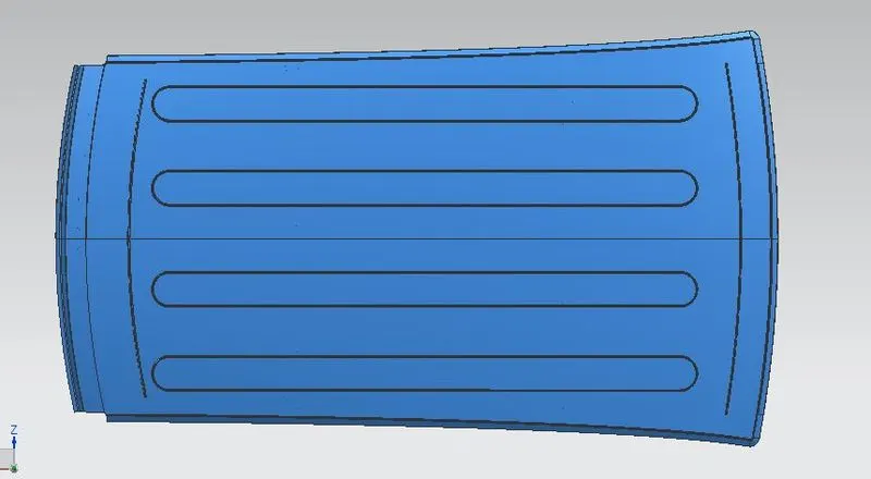
2. So incressed strength of the outer roof use to emboss feature
Incress strength use to emboss feature
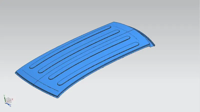
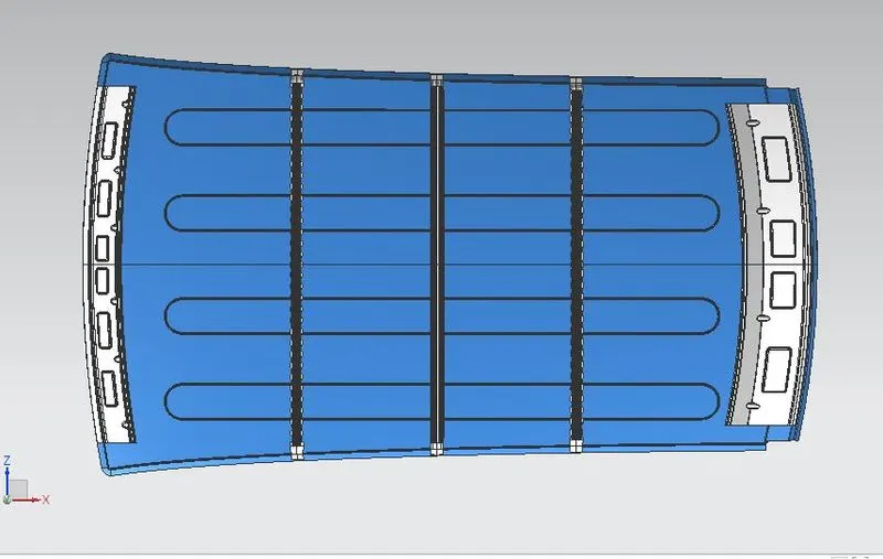
Different views of Roof
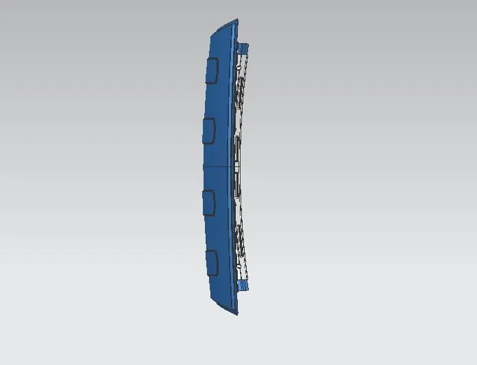
Conclusion :
1. To design and assembled successful automobile roof by using of NX CAD.
2. To checked heat distortion and snow load condition
3. snow load condition are un satisfied in some areas so created emboss in outer panel