Roof challenge
Introduction
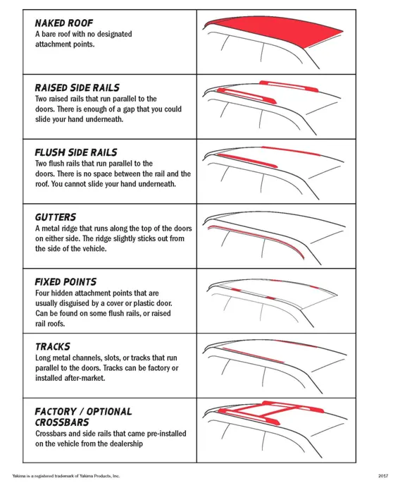
An automobile roof or car top is the portion of an automobile that sits above the passenger compartment, protecting the vehicle occupants from sun, wind, rain, and other external elements. Roof is connected to A-Pillar, B-Pillar, C-Pillar to cover the front and rear door. Roof is generally supported by a set of bow roof rails, centre roof rail, front and back roof rails. The roof designed must be strong enough to withstand impact loads during rollover accidents. Commonly used materials for roof construction include steel, aluminium. Following image shows the type of roofs.
Roof supports design
Front roof rail
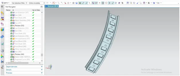
Front roof rail is designed according to the given master section. Embosses are made over the front roof rail to enhance its strength and other mechanical properties. A gap of 5mm is provided between the roof top surface and front roof rail. Uniform thickness of 0.75 mm is maintained throughout the section. Image below shows the designed front roof rail.
Rear roof rail
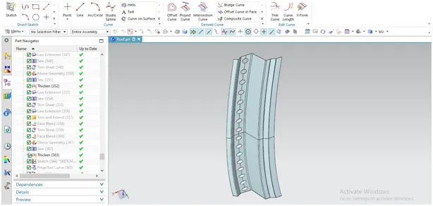
It will support the rear part of the roof. It should be designed with proper clearance to allow opening and closing of back door. A gap of 1.7 mm is provided between the roof top surface and rear roof rail. Uniform thickness of 0.75 mm is maintained throughout the section. Image below shows the designed rear roof rail.
Bow roof rails
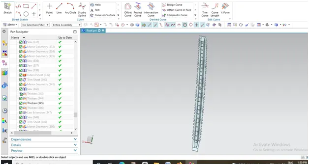
It is important support structure that supports the roof surface. Any load over the roof will be supported by it. The rear sides of the bow roof rails are spot welded to roof ditch area. It is also attached to the roof top surface using mastic sealant. A gap of 0.2 mm is provided between the roof ditch area and bow roof rail. Uniform thickness of 0.75 mm is maintained throughout the section. Image below shows the designed bow roof rail.
Center roof rail
Center roof rail must be stronger than other roof rails. The cross section of the centre roof is ‘W’ type, which ensures higher strength in the roof rail. Embossing is done on the surface to improve local strength of the roof rail. A gap of 0.2 mm is provided between the roof ditch area and centre roof rail. It is also attached to the roof top surface using mastic sealant. Uniform thickness of 0.75 mm is maintained throughout the section. Image below shows the designed center roof rail.
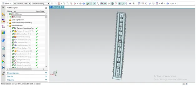
Image below shows the complete assembly of designed automobile roof
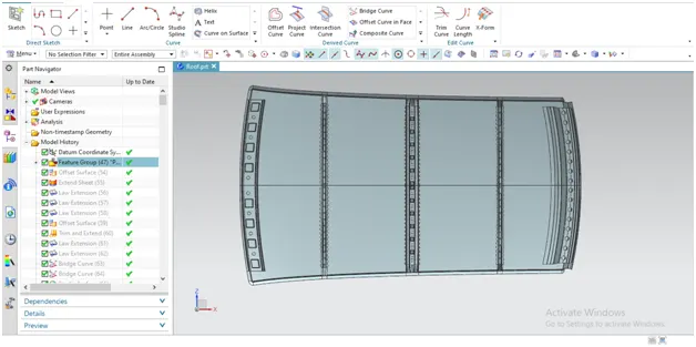
Curvature study
In this study we perform two types of calculations
- Heat distortion
- Snow load criteria
The curvature study is done only after the completion of design of roof.
Heat distortion calculation
This calculation is done to understand the better position of bow roofs. The strength of the roof varies when there is increase in temperature. Due to which sagging of the roof may occur. Better positioning of the bow roofs thus play crucial role as support structure.
Bow–roof position prediction Formula
W = [1.73 x 10^(-3) x L] + [1.85 x 10^(-8) x (R^2)/t] + [ 1.10x10^(-3) x l] - 2.68
Judgement Condition : OK< 2.7> 3.1
Where
L = Roof Length in X-Direction[mm](Roof dimension in 0-Y)
R = Roof curvature
R = 2(Rx*Ry)/(Rx+Ry)
Rx = X curvature
Ry = Y curvature
t = Roof plate thickness [mm]
l = Bow Roof Span [mm]
Procedure to measure Rx and Ry
- Enter the sketcher workbench by selecting a plane parallel to roof surface
- Draw a line at 3Y (-300 mm from the center line) and draw other two lines on either side of 3Y line, at a distance of 100 mm.
- Draw vertical lines between every adjacent roof rails as explained below
- First vertical line must be at center of the two rails
- Offset this vertical line 100 mm on either side.
- Select the intersection points to draw the 3 point curve
- Make all the lines as reference lines
- Project the intersection points on to the surface
- Measure local radius at this curves, which will give the Rx and Ry
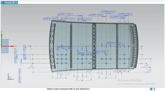
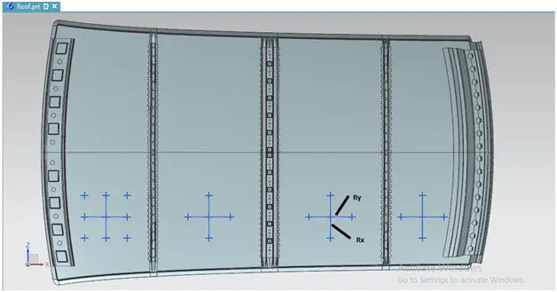
The values are tabulated below and W for each case is calculated
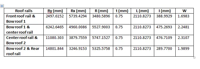
Result: All the ‘W’ values falls within the range and are acceptable.
Snow load condition
This calculation for automobiles is done in most of the European countries where snow fall is common. Snow loads are creep loads which may cause plastic deformation in the roof. As a design criterion, roof must regain its original shape once the snow is removed.
Snow load Prediction formula
Qr = [Iy x t2] / [α x s x [(Rx + Ry)/2]2 x 10-8]
Note: The Qr value given over here is correct. There was a typo error in the formula given in the video.
Where
α = My x Lx2 x 10-12 , My = Y(Ly-Y)
Judgement condition = Qr ≥ 3.1
250 ≤ s ≤ 380
t = Roof plate thickness [mm]
Ly = Distance between the front and rear roof Rails on the Vehicle along with 0Y[mm]
Length of Roof panel with the center point between Roof rail Front /Rear as the front and rear reference point.
Lx = Distance between the Left and Right end of the roof on the Roof BOW [mm]
Width of the roof panel exposed on the surface.
Y = Distance front Front Roof Rail to Roof BOW[mm]
s = Distance for which Roof BOW bears divided load [mm]
s = L1/2 + L2/2
Iy = Geometrical moment of inertia of Roof BOW (Y cross-section )[mm4]
Rx = Lateral direction curvature radius of roof panel Y cross-section on Roof BOW [mm]
Roof panel curvature Radius of the Length Lx in Front view
Ry = Longitudinal Direction curvature radius of the Roof panel X cross-section on Roof BOW [mm]
Roof panel X curvature radius of length s in Side view
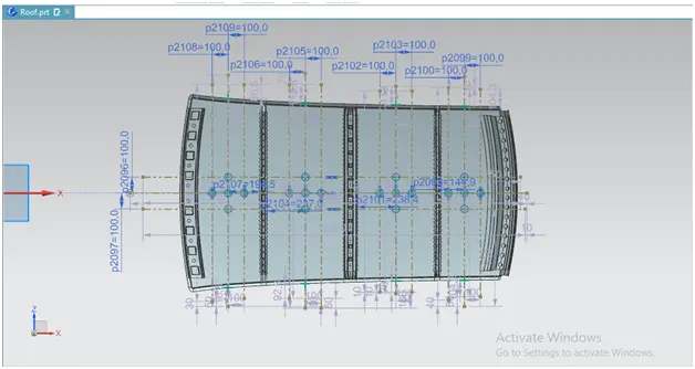
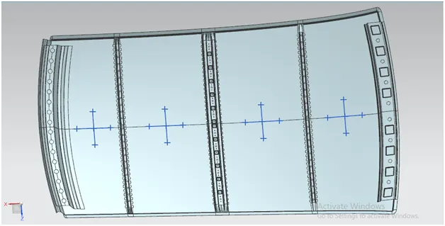
Procedure to measure Rx and Ry
- Enter the sketcher workbench. Draw a line along OY. Offset this line on either side to 100mm.
- Draw vertical lines between every adjacent roof rails as explained below
- First vertical line must be at center of the two rails
- Offset this vertical line 100 mm on either side.
- Select the intersection points to draw the 3 point curve
- Make all the lines as reference lines
- Project the intersection points on to the surface
- Measure local radius at this curves, which will give the Rx and Ry
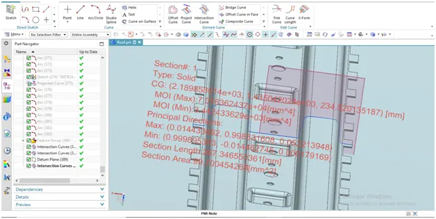
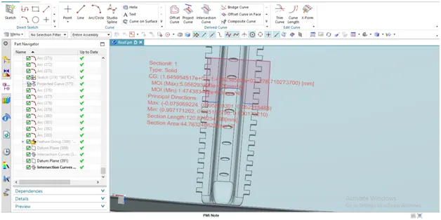
Moment of Inertia calculation
Bow roof 1
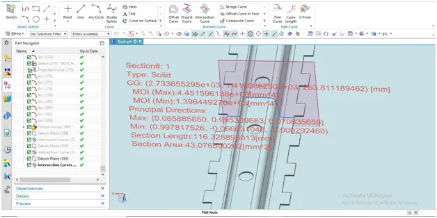
Centre roof rail
Bow roof 2
All the values are tabulated below and Qr is calculated
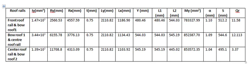
Result: All values for ‘Qr’ are within acceptable range.
Draft analysis
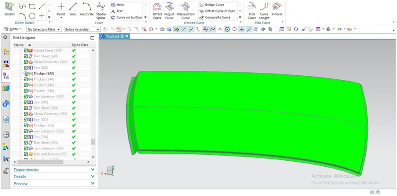
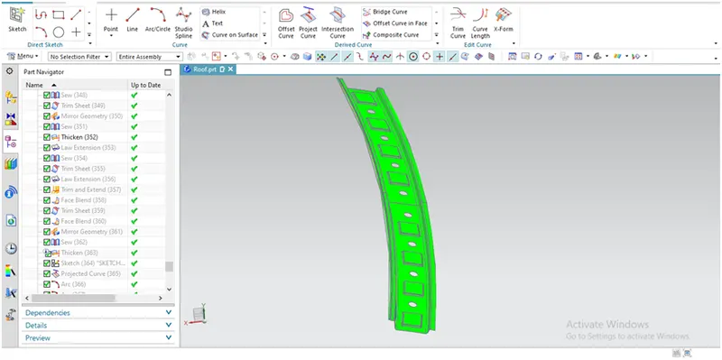
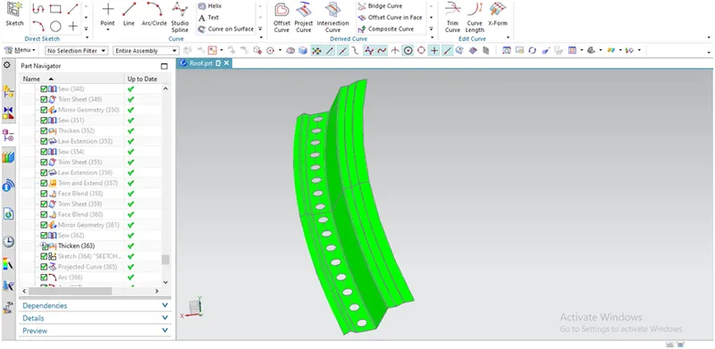
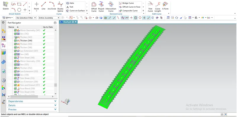
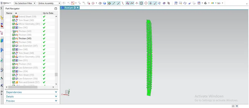
Draft analysis is performed to check the tooling feasibility. The minimum draft angle of 70 must be provided in case of sheet metal design to ensure deformation free ejection. The draft analysis for given automobile roof and its support structures are carried out, images are shown below
Roof top
Front roof rail
Rear roof rail
Centre roof rail
Bow roof
Conclusion
- For the given roof top surface class A, support structures are designed as per guidelines.
- Results of heat distortion and snow load calculations are within acceptable range.
- Draft analysis is carried out for each component and the results are satisfactory.