Roof challenge
ROOF DESIGN
introduction :
An automobile roof or car top is the portion of an automobile that sits above the passenger compartment, protecting the vehicle occupants from sun, wind, rain, and other external elements.
objective:
to perform the section modulus study for the master section and create the front and rear rail, center bow roof and bow roof one ND BOW Roof two create them accounting to their requirement.
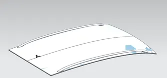
master section figure:
Requirements of design:
- the design requirements for the roof and its components.
- functional requirements.
- type of roofs and functionality.
- roll over test regulation and requirements.
- identification methods to increase the strength of the roof
- material identification techniques
- joining techniques like mastic and welding
- accessory part purpose and requirement’s (roof rack and roof molding)
- roll over test requirements and regulations.
DESIGN CONSIDERATION:
- Visibility criteria
- head clearance
- curvature study
- heat distortion and snow load criteria.
- material thickness.
- the operation performed in NX cad:
- create the assembly for the roof.
- every module has to be in one holder.
- extract the surface by using the extract command.
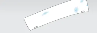
extracted sheet figure:
- un trim the extracted surface and offset at 0mm.
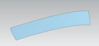
un trim surface figure:
- the sheet can be trim by using the extracted surface by using trim sheet surface.
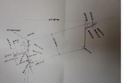
front roof rail ;
- by using this figure, create the front roof rail.
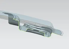
front roof rail.
- in a similar way rear roof rail part drawing sheet is provided.
- we have to create the rear roof rail.
- bow roof 1 and 2 and center bow roof as prepare accounting to their requirement.
- by using the roof, bow roof and center roofs are created
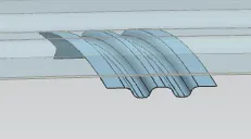
- center roof rail as to be width should be 60 to 70 mm.
- this type of roof is more stable.
- in a similar way do the bow roof one and bow roof two.
- when offsetting the sheet consider thickness as to be calculated o.75mm on both the sides.
final output :
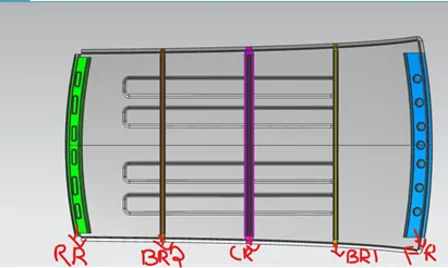
Main components of the roof
FRONT ROOF RAIL:
front roof rails are used in the assembly of a roof in which it provided mounting provision to windshield glasses and the changes in the front roof rail influences the front visibility of the passenger. the major design factor considered is headroom clearance. the front roof rail also provides provision for mounting the insider rear-view mirror.
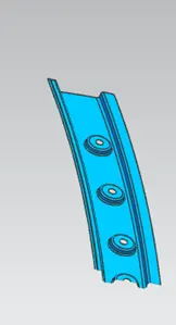
rear roof rail:
the rear roof rail is one of the important components of roof assembly which is used for the back door mounting similar to front roof rail important design considerations include rear clearance rear visibility of the vehicle.
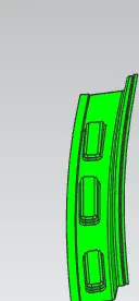
center roof rail.
the reinforcement center is used as a cross member between bodysides LH &RH respective . in the same cases, the reinforcement center is not joined with the roof and in some other cases, it is made to join in both roof and bodysides. the center and bow roof are joined with either spot weld or mastic sealants.
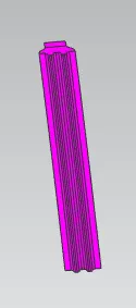
BOW ROOF ONE:
BOW ROOF ONE IS an additional stiffening member used in the roof assembly
To improve the localized strength.
it is joining directly to the roof itself with several spot welding or mastic sealant.
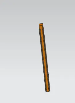
In a similar way bow roof two is also used to strengthening the roof:
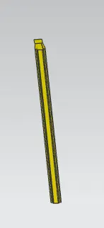
- curvature study:
center bow roof rail:
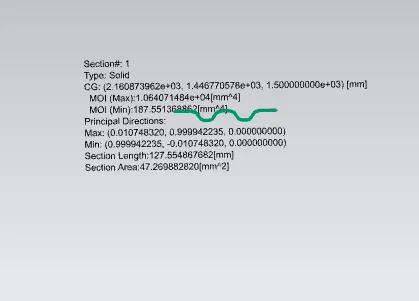
max inertia value :1,064071484e+04mm^4
min inertia value :187.55136886mm^4
Bow roof one:
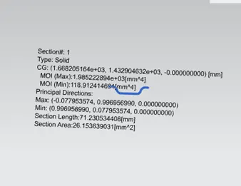
max inertia value: 1.98522894e+03mm^4
min inertia value: 118.912414694mm^4
bow roof two:
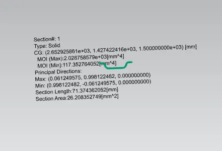
max inertia value: 2.028758579e+03mm^4
min inertia value : 117.352764052mm^4
Heat distortion criteria:
Heat distortion temperature is the temperature at which metal softens and deforms under a specified load. From Heat distortion criteria, roof strength can be enhanced by appropriate positioning of bow roof rails
W = [1.73 x 10^(-3) x L] + [1.85 x 10^(-8) x (R^2)/t] + [ 1.10x10^(-3) x l] - 2.68
Judgement Condition : OK< 2.7> 3.1
Where
L = Roof Length in X-Direction[mm](Roof dimension in 0-Y)
R = Roof curvature
R = 2(Rx*Ry)/(Rx+Ry)
Rx = X curvature
Ry = Y curvature
t = Roof plate thickness [mm]
l = Bow Roof Span [mm]
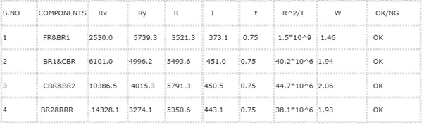
SONW LOAD CERITIRA:
The evaluation is performed in cold regions where snow occurs. Roof design must pass through these calculations to ensure that it has sufficient stiffness to withstand the load due to the accumulation of snow over the roof.
Qr = [Iy x t2] / [α x s x [(Rx + Ry)/2]2 x 10-8]
Note: The Qr value given over here is correct. There was a typo error in the formula given in the video.
Where
α = My x Lx2 x 10-12 , My = Y(Ly-Y)
Judgement condition = Qr ≥ 3.1
250 ≤ s ≤ 380
t = Roof plate thickness [mm]
Ly = Distance between the front and rear roof Rails on the Vehicle along with 0Y[mm]
Length of Roof panel with the center point between Roof rail Front /Rear as the front and rear reference point.
Lx = Distance between the Left and Right end of the roof on the Roof BOW [mm]
The width of the roof panel is exposed on the surface.
Y = Distance front Front Roof Rail to Roof BOW[mm]
s = Distance for which Roof BOW bears divided load [mm]
s = L1/2 + L2/2
Iy = Geometrical moment of inertia of Roof BOW (Y cross-section )[mm4]
Rx = Lateral direction curvature radius of roof panel Y cross-section on Roof BOW [mm]
Roof panel curvature Radius of the Length Lx in Front view
Ry = Longitudinal Direction curvature radius of the Roof panel X cross-section on Roof BOW [mm]
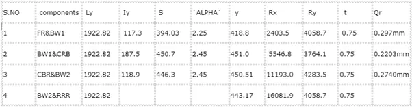
- value is less than 2.1
- we have to add more strength to the roof by using emboss.
- Emboss well go the more strength to the roof.
given figure below .
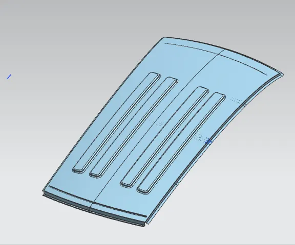
figure:
Draft analysis:
Roof Outer panel :
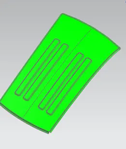
Do the draft analysis of the roof outer panel after thickening.
Select the plane and set the vector then do to draft analysis.
Select the vector
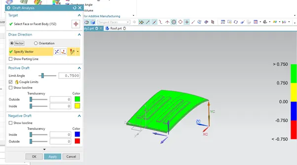
front roof rail:
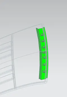
draft analysis for front rood rail.
Center bow roof:
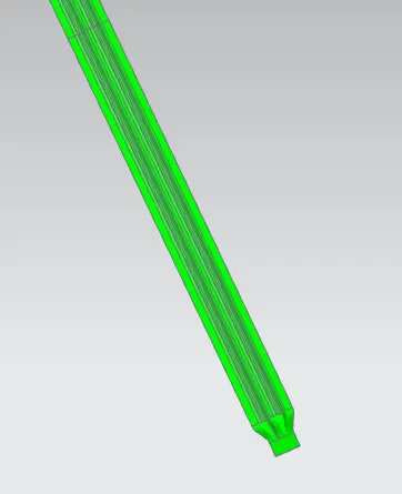
draft analysis:
Bow roof 1:
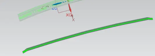
Draft analysis
Bow roof 2:
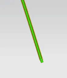
Rear roof rail:
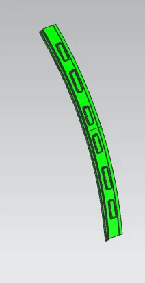
Draft analysis of rear roof rail.
Draft analysis as done on all solid parts .