Roof challenge
Aim- Roof design using NX 12 and its optimization by calculating heat distortion criteria,snow load criteria and section inertia analysis.
Objective-
1.To develop essential flanges and reinforcements from the input styling surface.
2.Provide appropriate dimension and check for draft analysis and perform section modulus on the 0-Y section.
3.To do a carvature study on the roof and perform calculations to determine the position of the bow -roof.
Inputs-
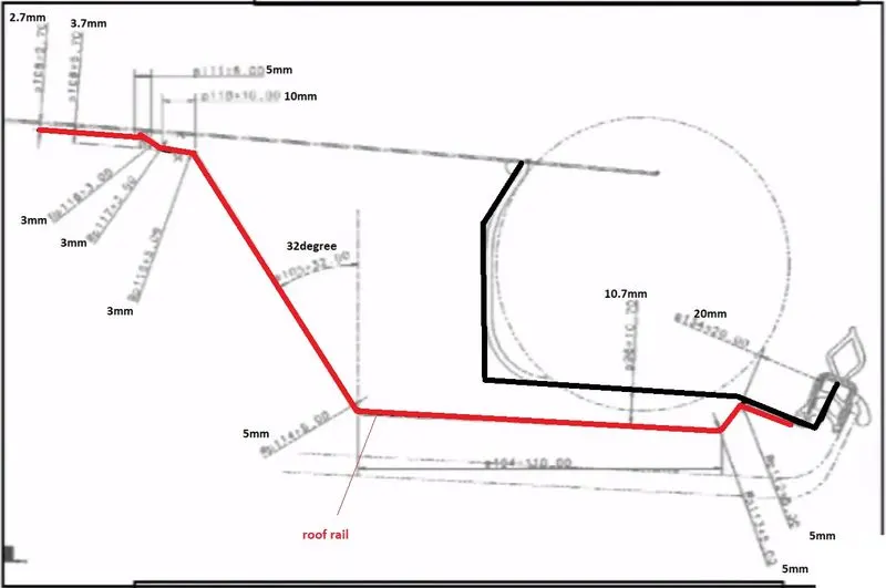
Master section for rear roof rail
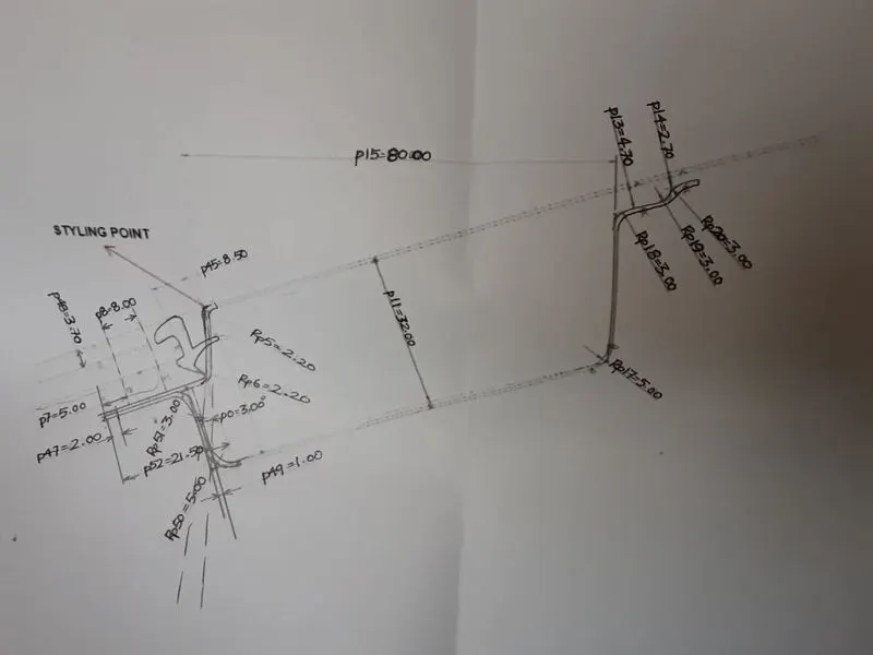
Master section for front roof rail
Roof- An automobile roof can be termed as a protective structure that keeps the passenger of the vehicle safe from external elements like weather ,flying debris, and one of its main purposes is to protect the inhabitants of the vehicle from sustaining any injuries during rollover incidents and sudden impacts on roof.
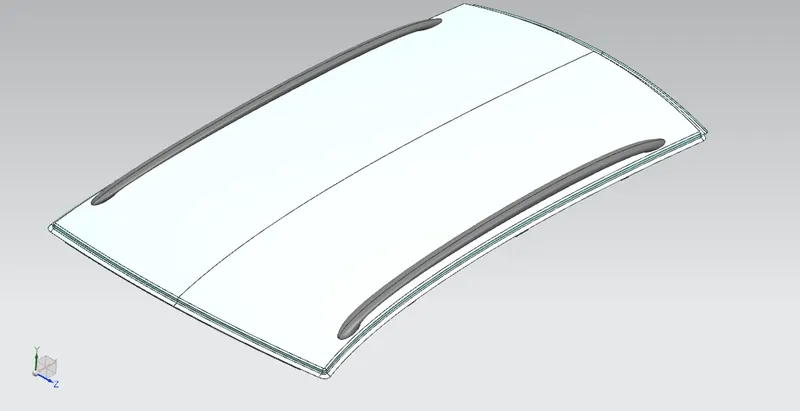
- The roof itself is not a single component but an assembly of various parts and structure that from the roof assembly.
- It consists of an outer panel that provides covering and forms the top portion of the vehicle and also provides good aesthetics and strength to the vehicle.
- They are various components under the outer panel that form an internal structure which adds a lot of strength to the roof portion.
- And these components are the reason for the roof not getting caved in during rollover incidents of the vehicle.
Structural components of the roof
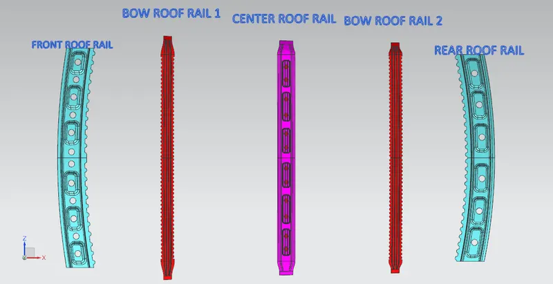
- Front roof rail reinforcement (FR)
- Bow roof rail reinforcement 1 (BR1)
- Center roof rail reinforcement primary (CR)
- Center roof rail reinforcement secondary
- Bow roof rail reinforcement 2 (BR2)
- Rear roof rail reinforcement (RR)
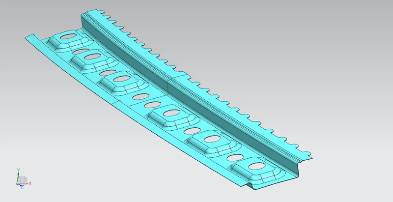
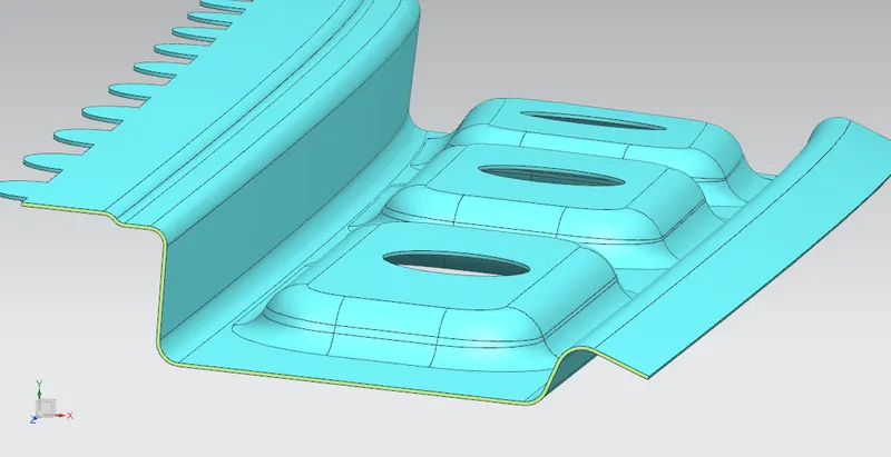
1. Front roof rail reinforcement ( FR)
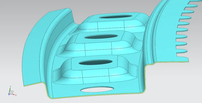
It is the support that joins the windshield glass, body side outer, and the inner panels. It is usually made from body side outer scrap and therefore the thickness of the rail is 1.25 mm .A draft angle of 3-5 degree is provided for deep drawing operation. The visibility criteria and the headroom clearance of the passanger are taken as design considerations.
2.Bow roof rail 1 and 2 reinforcement-
These are the intermediate structural components of the roof that are added in order to provide support along with the three primary roof rails (FR,CR,RR).The number of bow roof rails may vary depending on the class of the vehicle . Some vehicles may not have bow roof at all.It all depends on the design intent.These are joined to the roof by using mastics.
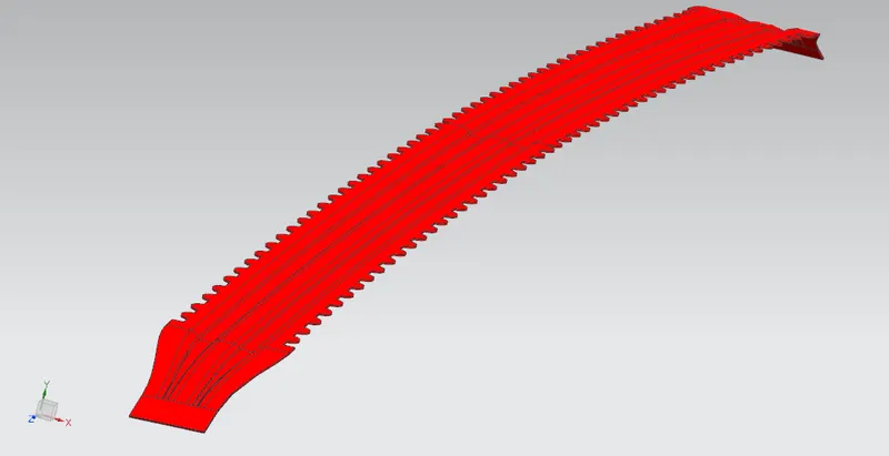
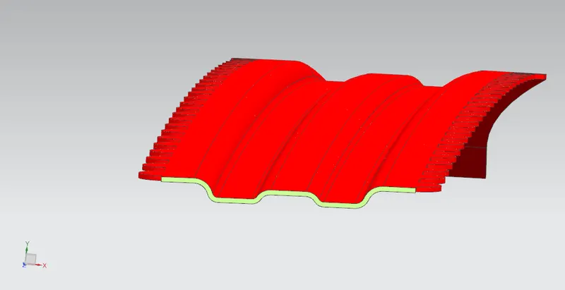
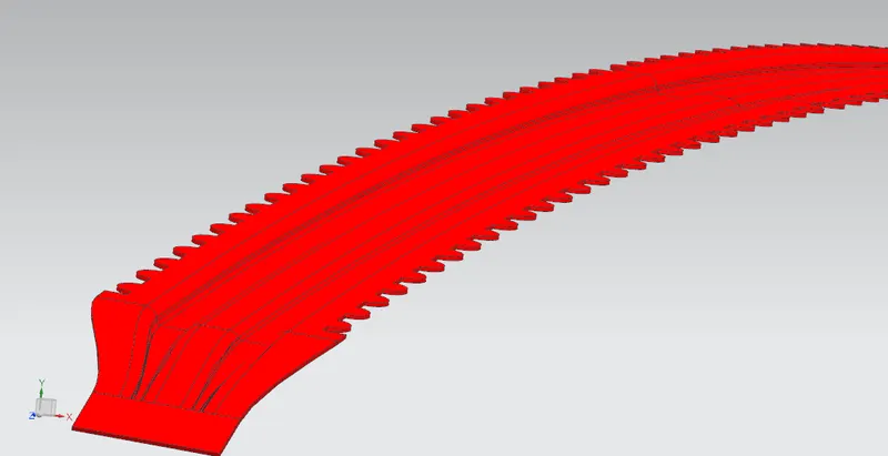
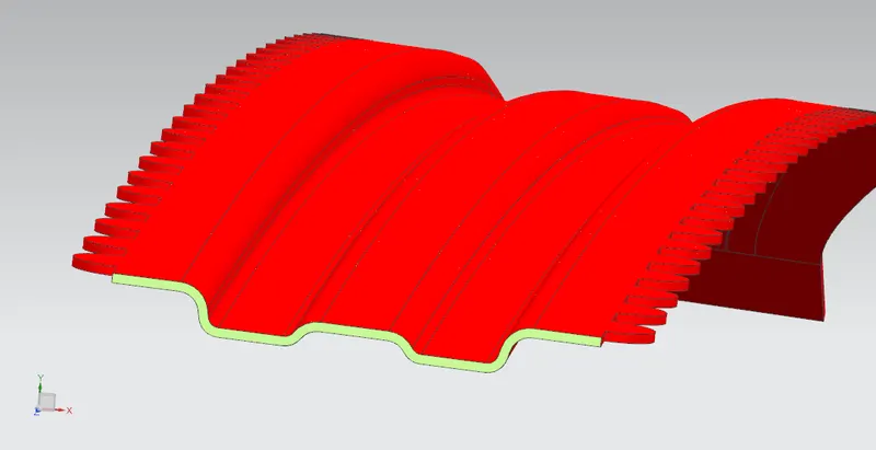
Embosses are added for additional strength.
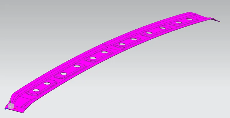
3. Center roof rail reinforcement (CR)-
The center roof rail is placed at exact middle portion of the roof in some cases a secondary rail is embeded in to the center rail for added strength.The design inputs are taken from carvuter of the roof at the CR position it is joined with mastics to the roof instead of spot welds as it placed under styling surface.
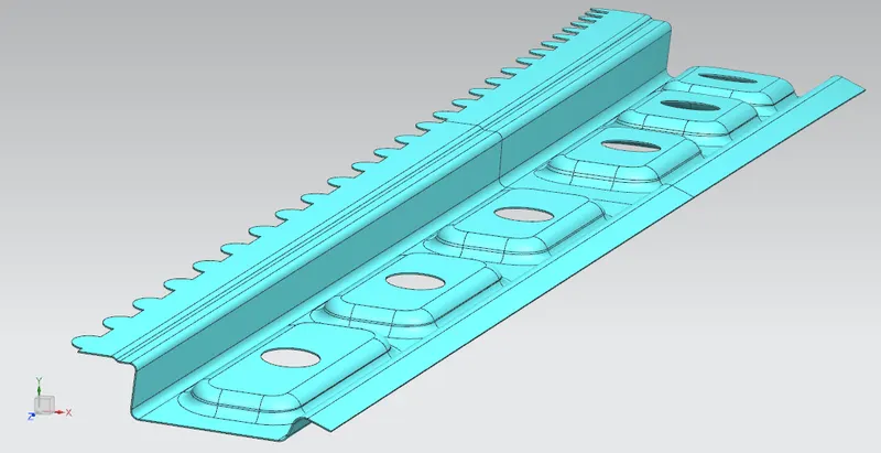
4.Rear roof rail reinforcement (RR)-
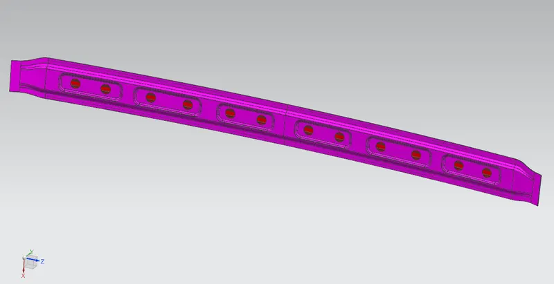
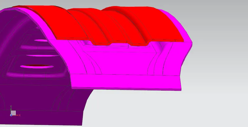
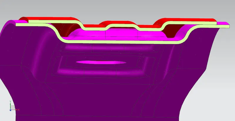
It is the support that is joined to the backdoor the bodyside outer and the inner panels.Inputs from the backdoor design is also taken to accommodate there required clearance along with headroom clearance and the rear visibility criteria while designing the rear roof rail. Spot welds are applied at the backdoor end af the rail and the other end is joined with the roof using mastic sealants.
Complete roof design
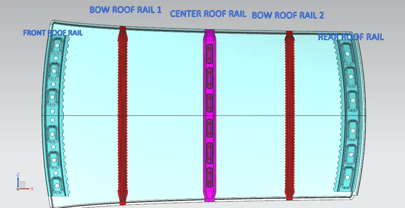
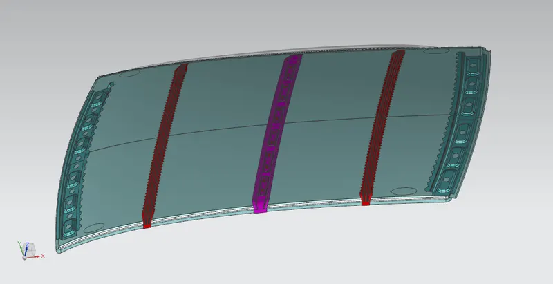
Calculation for determining the bow roof position-
Heat distortion criteria-
Heat distortion temperature is the temperature at which the metal softens and deforms under a specific load. This study is done to check the ability of the roof to withstand high temperature with respect to the positioning of the reinforcements which contribute to increased strength.
Created sketches for heat distortion calculation
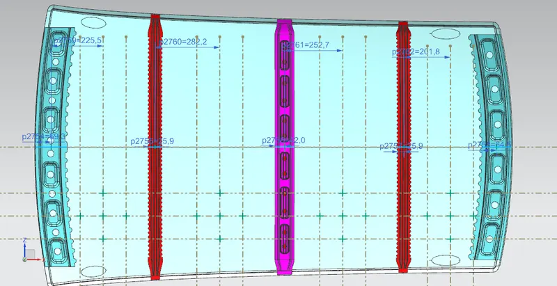
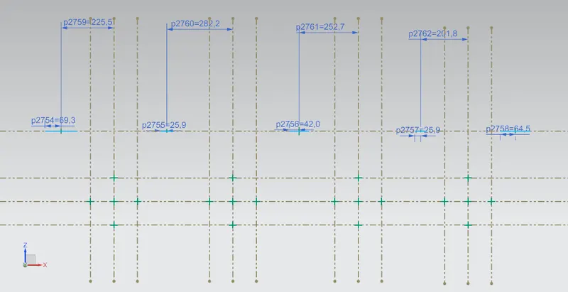
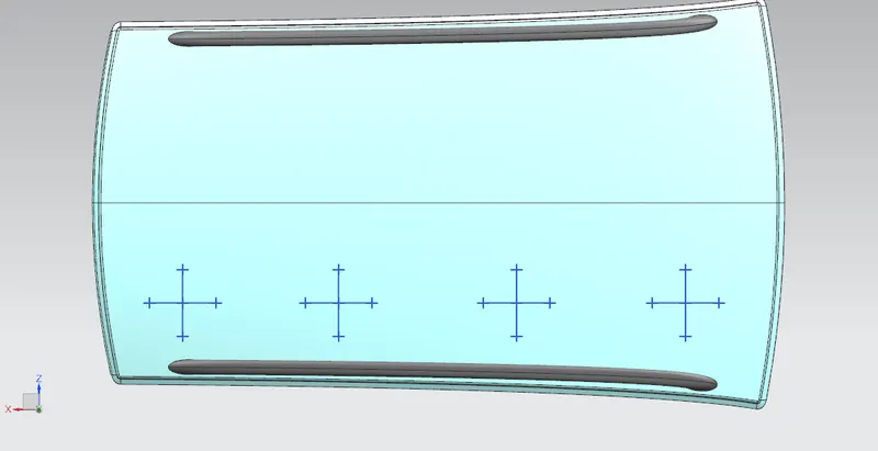
Heat distortion prediction formula
W=[1.73×10^(-3)×L]+[1.85×10^(-8)×(R^2)/t]+[1.10×10^(-3)×I]-2.68
Judgement condition- OK<2.7>3.1
Where
L=Roof length in X- Direction[mm](Roof dimension in 0-Y)
R= Roof carvature
R= 2(Rx×Ry)/(Rx+Ry)
Rx= X Carvature
Ry= Y Carvature
T= Roof plate thickness[mm]
I= Bow roof span [mm]
|
BOW |
Rx |
Ry |
R |
I |
L |
t |
W |
OK/NG |
|
FR&BR1 |
5747.77 |
2466.65 |
3452 |
356 |
2032.6 |
0.75 |
1.52 |
OK |
|
BR1&CR |
4926.48 |
6414.30 |
5572.8 |
496.4 |
2032.6 |
0.75 |
2.14 |
OK |
|
CR&BR2 |
3907.26 |
10982.42 |
5763.8 |
451.5 |
2032.6 |
0.75 |
2.15 |
OK |
|
BR2&RR |
3218.37 |
15052.35 |
5303 |
313.123 |
2032.6 |
0.75 |
1.87 |
OK |
From the above resuilts it is concluded that the desired designed roof satisfies the heat distortion criteria.
Snow load criteria-
Snow load criteria study is done to check the ability of the roof to withstand snowfall and bounce back to its original shape without any permanent deformation once the load is removed.
Created sketches for snow load criteria
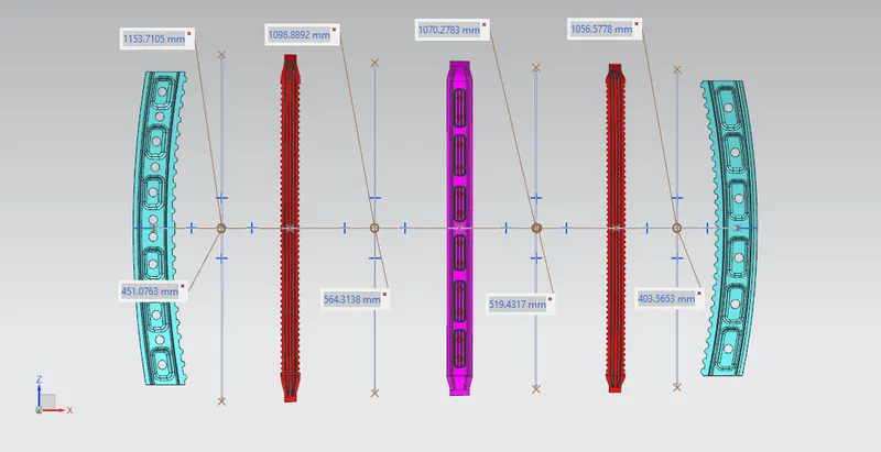
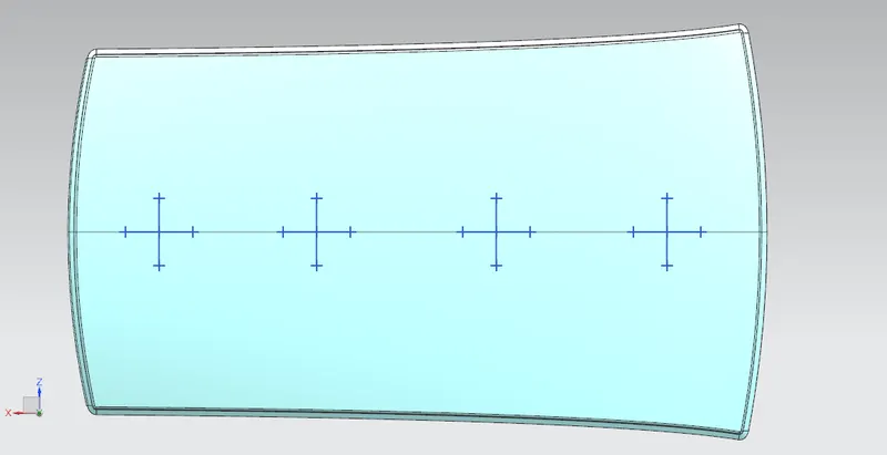
Snow load prediction formula-
Qr = [Ly×t^2]/[α×s×[(Rx+Ry)/2]^2×10^-(8)]
Where
α = My×Lx^2×10^-12
My= Y(Ly-Y)
Judgement condition =Qr≥3.1 and 250≤Qr≤380
T = Roof plate thickness
Ly = Distance between the front and rear roof rail on the vehicle along with 0-Y
Lx = Distance between the left and right end of the roof on the roof bow.
Y = Distance for which roof bow bears divided load
S = Distance for which roof bow bears divided load
S= L1/2+L2/2
Iy = Geometrical moment of inertia of roof bow along Y cross section
Rx = Lateral direction curvature radius of roof panel along Y cross section
Ry = Longitudinal direction curvature radius of the roof panel along X cross section
|
BOW |
Lx |
Ly |
Rx |
Ry |
α |
Iy |
s |
t |
y |
Qr |
OK/NG |
|
FR-BR1 |
1153.71 |
2032.6 |
4589.7 |
2531.2 |
0.9 |
12610 |
507.65 |
0.75 |
451 |
110.21 |
OK |
|
BR1-CR |
1098.88 |
2032.6 |
3780.2 |
6331.1 |
1 |
137638 |
541.5 |
0.75 |
564.3 |
559.3 |
OK |
|
CR-BR2 |
1070.27 |
2032.6 |
4312.8 |
11576 |
0.9 |
12970 |
461.4 |
0.75 |
519.43 |
25.047 |
OK |
From the above resuilt it is concluded that the designed roof satisfies the snow load criteria.
Section modulus study
Section modulus calculation for front roof rail
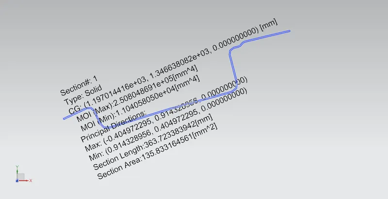
Section modulus = I/Y
I max = 250804 mm^4
y = 148.70/2 = 74.35 mm
S = 3.373*10^3 mm^3
Section modulus calculation for bow roof rail 1
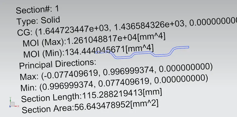
Section modulus = I/Y
I max = 12610 mm^4
y = 52/2 =26 mm
S = 4.85*10^2 mm^3
Section modulus calculation for center bow roof rail
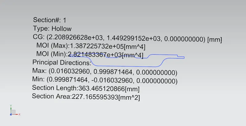
Section modulus = I/Y
I max = 138722 mm^4
y = 84/2 =42 mm
S = 3.302*10^3 mm^3
Section modulus calculation for bow roof rail 2
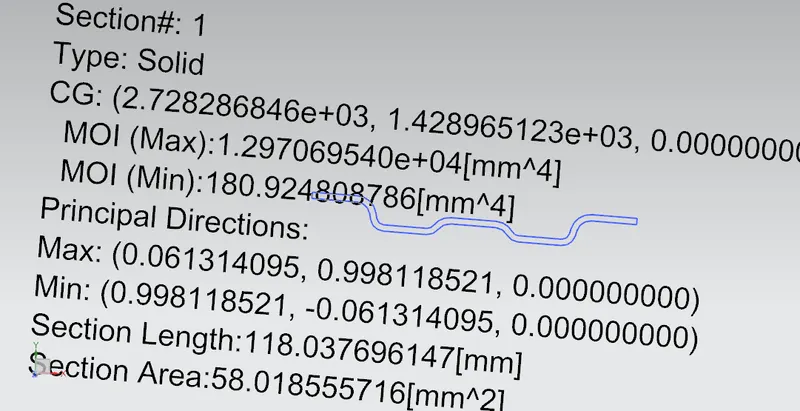
Section modulus = I/Y
I max = 12970 mm^4
y = 52/2 =26 mm
S = 4.98*10^2 mm^3
Section modulus calculation for rear roof rail
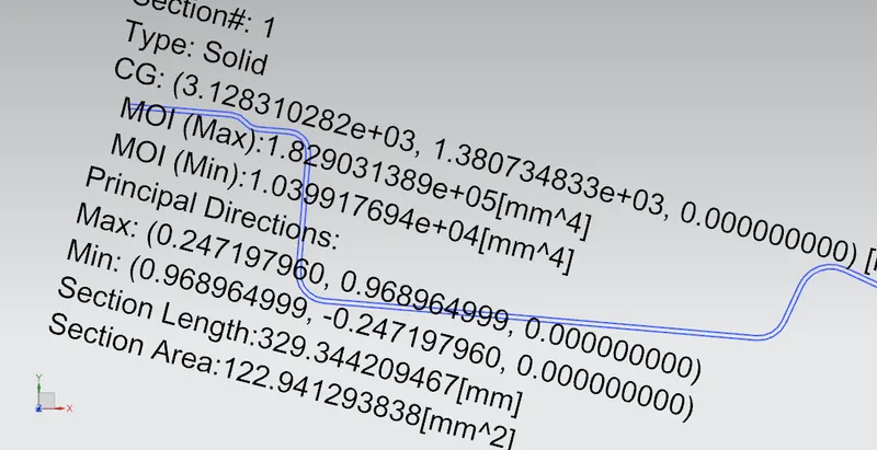
Section modulus = I/Y
I max = 182903 mm^4
y = 134/2 =67 mm
S = 2.729*10^3 mm^3
Section modulus calculation for roof outer panel
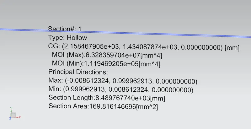
Section modulus = I/Y
I max = 63283597mm^4
y = 2032.6/2 =1016.3 mm
S = 62.268*10^3 mm^3