Roof challenge
Designing of Car Roof by Considering Heat Distortion and Snow Load Criteria in NX CAD
Objective: The main objective of this project is to understand the design process to design the roof with all the roof rails and to understand the calculations behind it. Also, to learn about the different tools used in NX cad for designing.
INTRODUCTION:
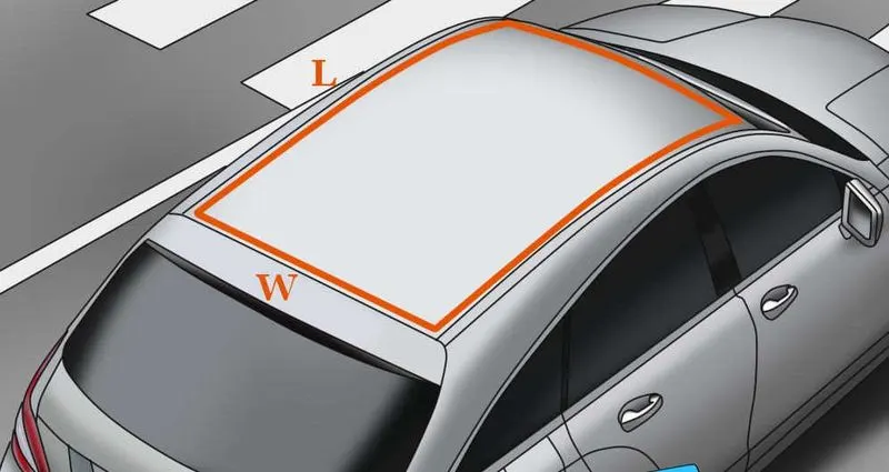
Roof: Roof of an automobile is that commodity which sits above the passenger compartment. Roof houses the vehicle as shielding part which safeguards the occupants from sunlight, heat, rain, wind, dust, etc.
In the past roof was introduced as cover for passenger compartment but later on, it also used as a luggage carrier, sunroof and in recent past years with the introduction of the solar panelled electric vehicle got a major boost in the automotive industry.
Roof has the following functions:
- protects from external damage
- prevents passenger and vehicle from accidents
- luggage carrier
- design of the roof also affects in giving aerodynamic shape to vehicle
- sunroof
- solar panelled roof in EV
Since the roof has numerous functions so the roof has to be stronger enough to withstand the damage experienced by it.
DESIGN CONSIDERATIONS FOR A ROOF:
- Visibility criteria
- Head clearance
- Curvature study
- Heat distortion and snow load criteria
- Draft analysis
Why Reinforcements?
If the roof is flat, it is very weak and cannot able to with stand the forces like snow, so in order to increase the strength of the roof these reinforcements like front roof rail, central roof rail, rear roof rail and the bow roofs are introduced and joined to the flat surface of the roof with the different joining process.
Different types of reinforcements that the car has are:
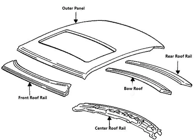
- Front roof rail
- Bow roofs
- Central roof rail and
- Rear roof rail
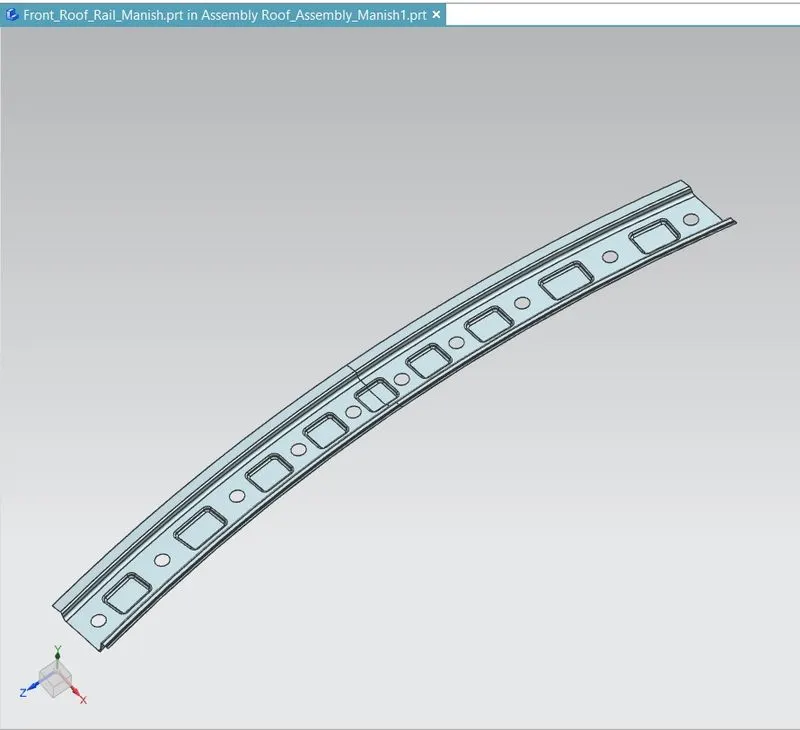
Front Roof Rail:
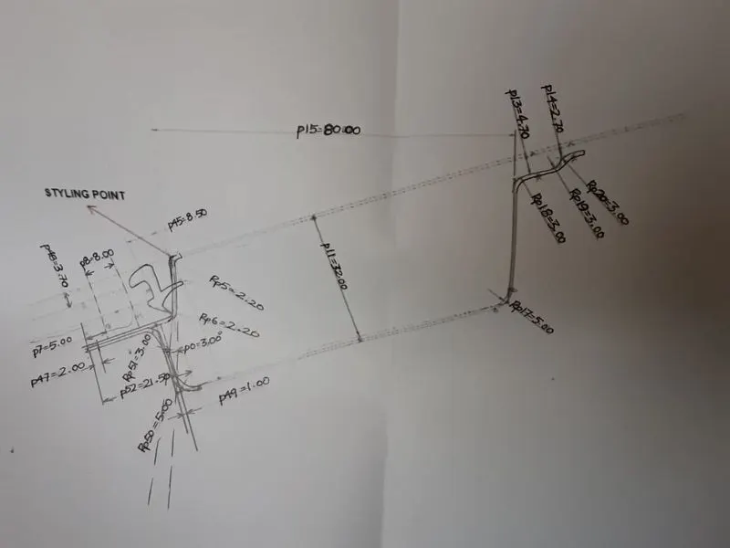
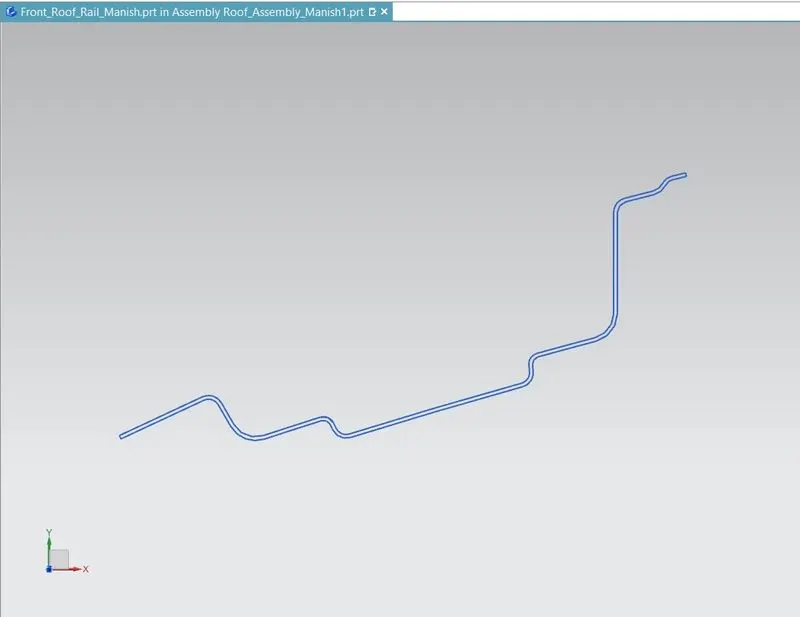
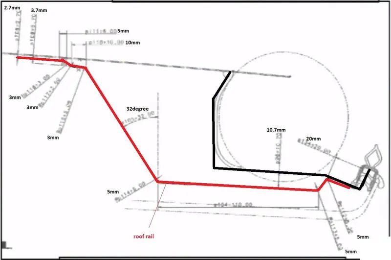
Front roof rail is the one which joins the wind shield glass, body side outer and the inner panel also. Here the front roof rail is designed based up on the master section given
Master sketch:
Model view of Front roof rail:
Master Section of Front roof rail:
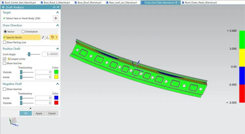
Draft Analysis of Front Roof Rail:
Rear Roof Rail:
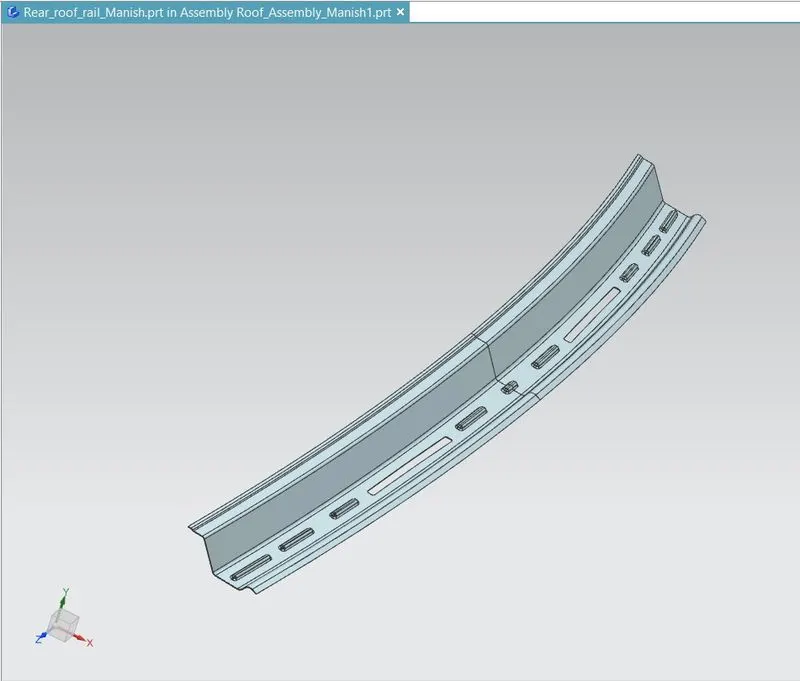
Rear roof rail is the one which joins the back door and the body side out.
Master Sketch:
Model view of Rear roof rail:
Master section of Rear roof rail:
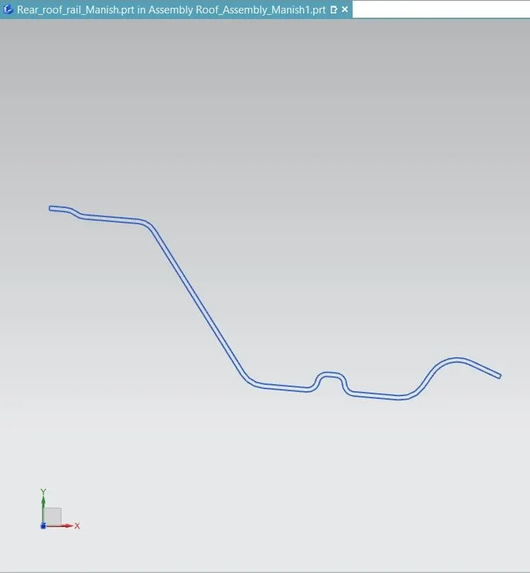
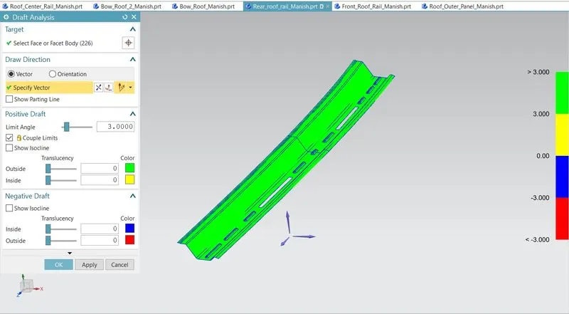
Draft Analysis of Rear Roof Rail:
Central Roof Rail:
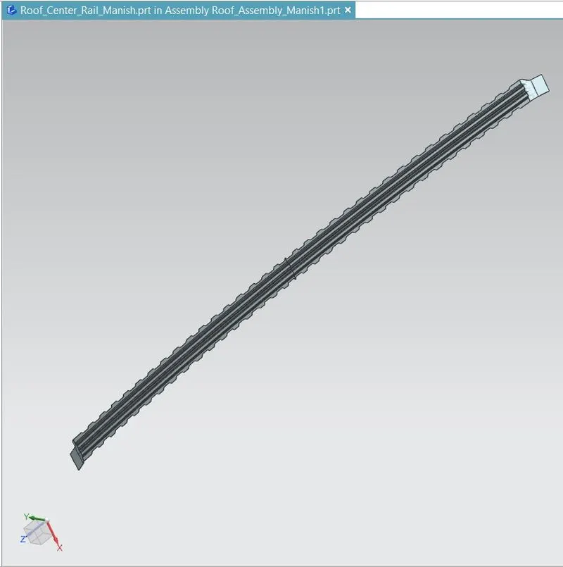
Central roof rail helps in providing effectively support to the flat area of the roof as it is more susceptible to failure under the action of load. generally central roof rail is placed at the centre of the roof which is connected to the B-pillar support structure.
Model view of Central roof rail:
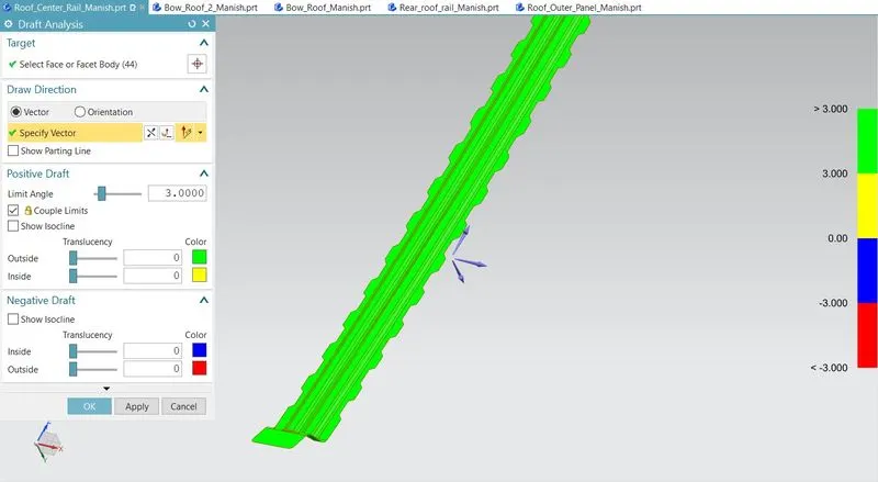
Draft Analysis of Central Roof Rail:
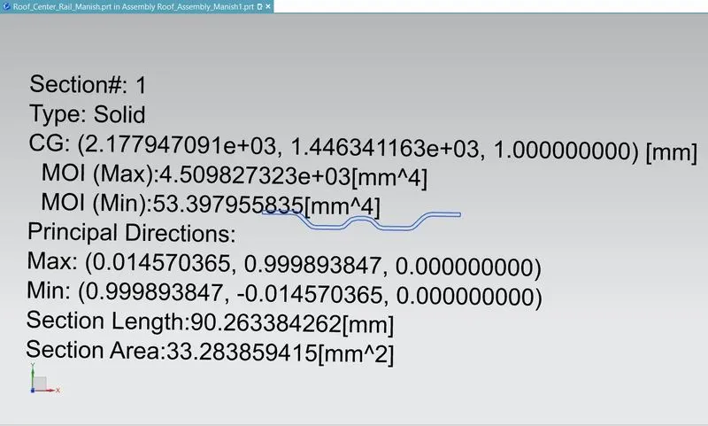
MOI of Central roof rail:
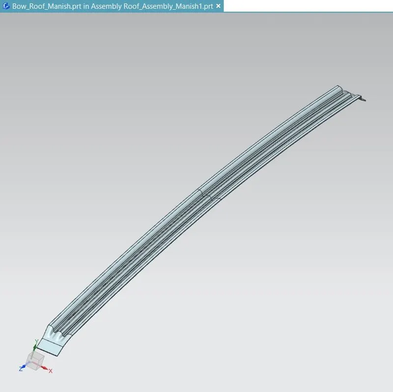
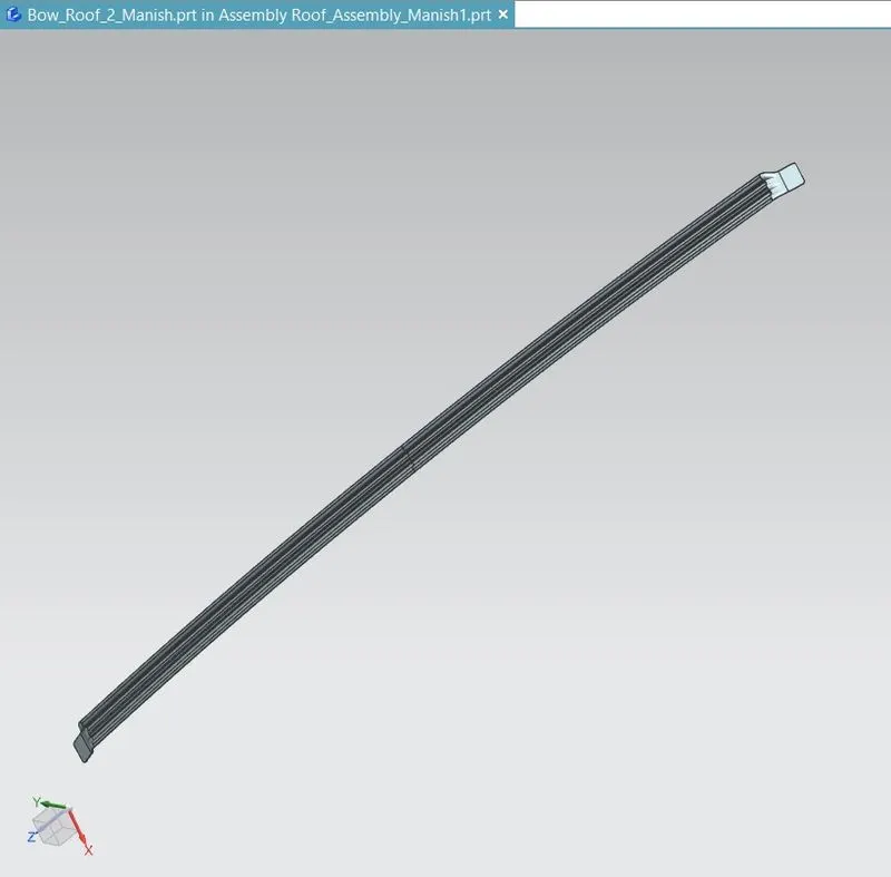
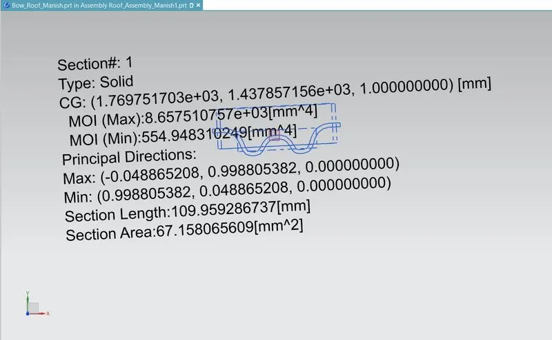
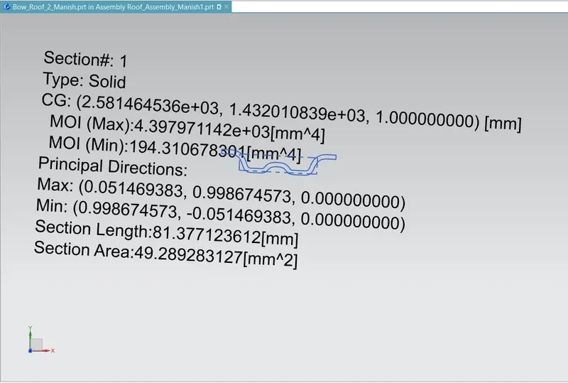
Bow Roof: The bow roofs are given to improve the torsional stiffness and load bearing capacity of the roof structure. The number of bow roof present is depending on the overall size of the roof. Presently in this project two bow roofs are added.
Model view of both the Bow roofs:
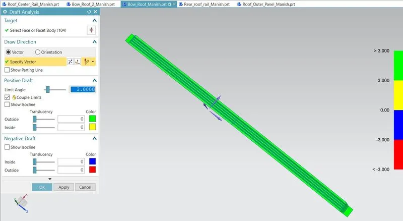
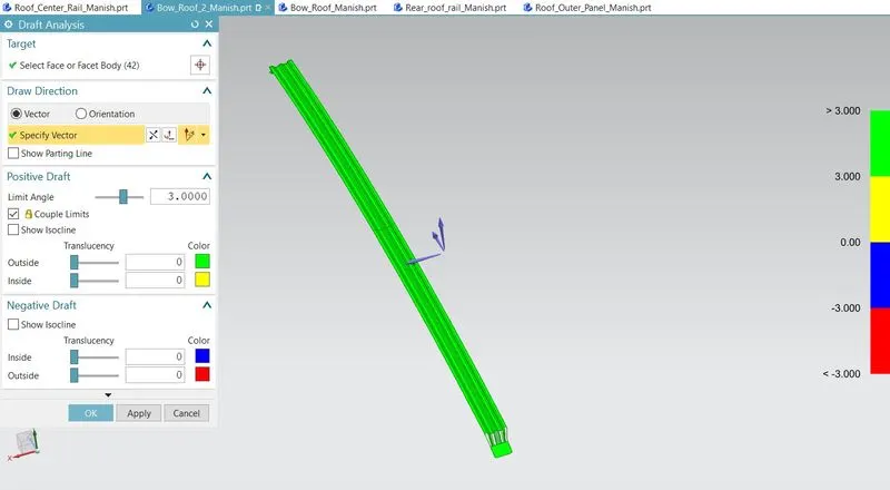
Draft Analysis of Bow Roof:
MOI of Bow Roof:
Formulation & Calculation:
Heat Distortion Criteria:
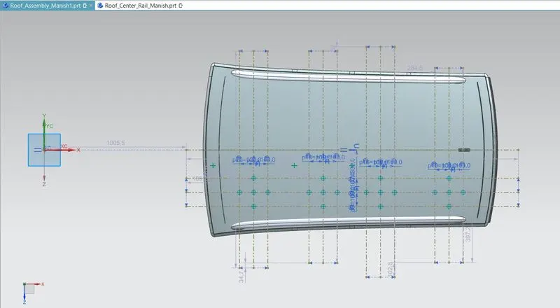
The heat radiating from the sun causes the roof of the car to change in the metallic regions. Heat distortion criteria indicate what temperature materials start to "soften" when exposed to a fixed load at elevated temperatures.
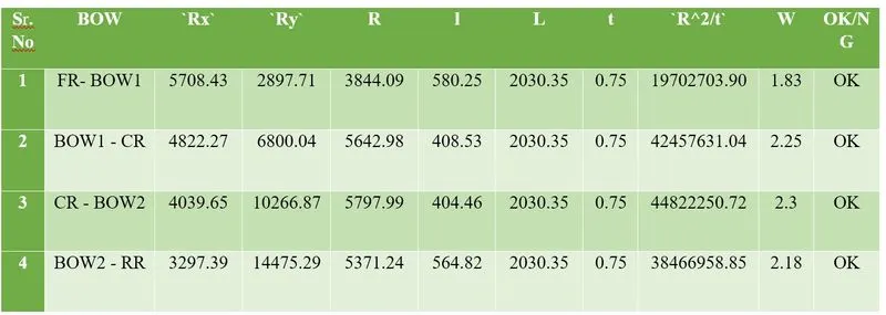
W = [1.73 x 10^(-3) x L] + [1.85 x 10^(-8) x (R^2)/t] + [ 1.10x10^(-3) x l] - 2.68
Where
L = Roof Length in X-Direction[mm](Roof dimension in 0-Y)
R = Roof curvature
R = 2(Rx*Ry)/(Rx+Ry)
Rx = X curvature
Ry = Y curvature
t = Roof plate thickness [mm]
l = Bow Roof Span [mm]
Judgement Condition: OK< 2.7mm
As per Calculations we get the value of W and see the results
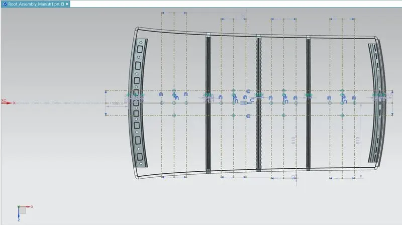
Snow load Prediction:
Qr = [Iy x t2] / [α x s x [(Rx + Ry)/2]2 x 10-8]
Where
α = My x Lx2 x 10-12 , My = Y(Ly-Y)
Judgement condition = Qr ≥ 3.1
250 ≤ s ≤ 380
t = Roof plate thickness [mm]
Ly = Distance between the front and rear roof Rails on the Vehicle along with 0Y[mm]
Length of Roof panel with the center point between Roof rail Front /Rear as the reference point of the front and the rear.
Lx = Distance between the Left and Right end of the roof on the Roof BOW [mm]
Width of the roof panel exposed on the surface.
Y = Distance front Front Roof Rail to Roof BOW[mm]
s = Distance for which Roof BOW bears divided load [mm]
s = L1/2 + L2/2
Iy = Geometrical moment of inertia of Roof BOW (Y cross-section )[mm4]
Rx = Lateral direction curvature radius of roof panel Y cross-section on Roof BOW [mm]
Roof panel curvature Radius of the Length Lx in Front view
Ry = Longitudinal Direction curvature radius of the Roof panel X cross-section on Roof BOW [mm]
Roof panel X curvature radius of length s in Side view
As per the calculation we get
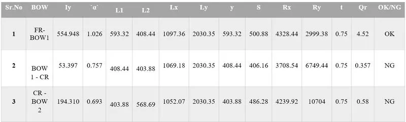
- As you know our Roof design does not get satisfying in the snow load prediction. because in some areas the values were below 3.1
- there are some cases our roof may design may face this kind of problems. To neutralizing this problem, we can do some action to get passes in the real-time Snow load test. those are given below.
- Redesign the bow to improve the moment of inertia
- make changes in the position of bow's
- Add an extra bow make some bead or embossed on the roof to strengthening the roof from its displacement.
- passes the test report to the Styling team to change the radius of curvature of the part.
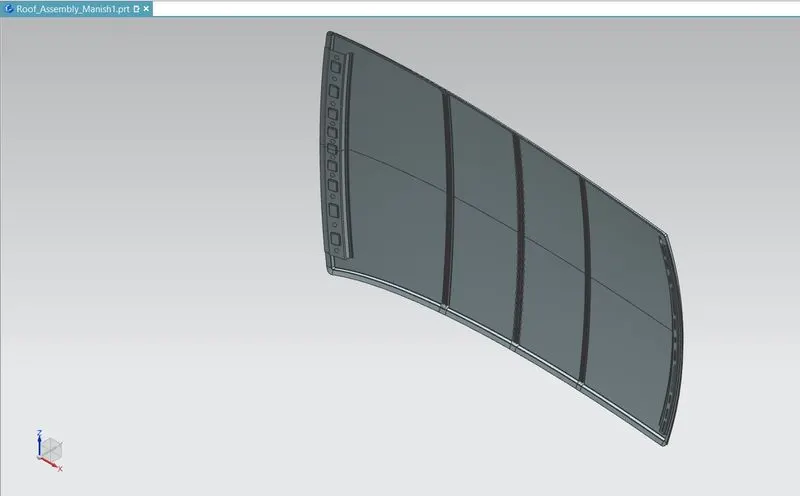
Roof Assembly:
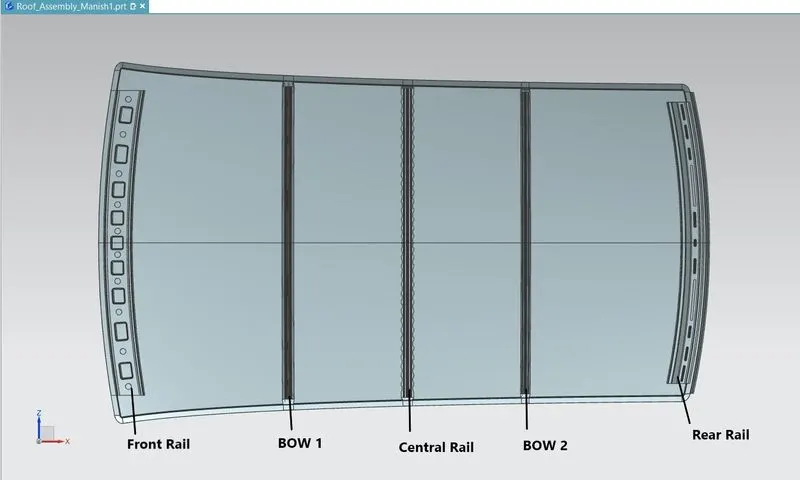
Isometric View:
Section Modulus:
Section modulus is a geometric property for a given cross-section used in the design of beams. Other geometric properties used in the design include an area for tension, radius of gyration for compression, and moment of inertia for stiffness. The Section modulus is defined as
`S = I/y`
Where,
S = Section Modulus
I = Moment of Inertia
y = Distance from the neutral axis to any given part.
Draft Analysis:
In the real-world application of manufacturing of sheet metals with some operations like hot and cold rolling, punching etc. The angle modelled in the CAD software for this component should be applicable for the real-world manufacturing processes also.
So, in the CAD software, some analysis can be made to precheck the operations that can be performed in Manufacturing industries. Draft analysis is one of the analyses that check the angle between the components which are operated in sheet metals.
CONCLUSION: The design of roof and all components was performed based on given data. It was found that the design fulfilled heat distortion criteria condition. To avoid the out-of-range Qr value and get it into required range for one condition in snow load criteria, it is recommended to add embosses to the rear part of roof to increase local strength and hence the Qr value.