Advanced Sheet Metal Design Using NX Cad Challenge_1_Casing Design
Advanced Sheet Metal Design Using NX Cad - Casing Design
Objective –
- Main objective of the project is to design casing in NX cad application workbench.
- To perform the drafting of the part.
- To learn about features of NX cad
Introduction –
Sheet metal is metal formed by an industrial process into thin, flat pieces. Sheet metal is one of the fundamental forms used in metalworking, and it can be cut and bent into a variety of shapes. Countless everyday objects are fabricated from sheet metal. Thicknesses can vary significantly; extremely thin sheets are considered foil or leaf, and pieces thicker than 6 mm (0.25 in) are considered plate steel or "structural steel".
Sheet metal is used in automobile and truck (lorry) bodies, airplane fuselages and wings, medical tables, roofs for buildings (architecture), and many other applications.
Design Methodology –
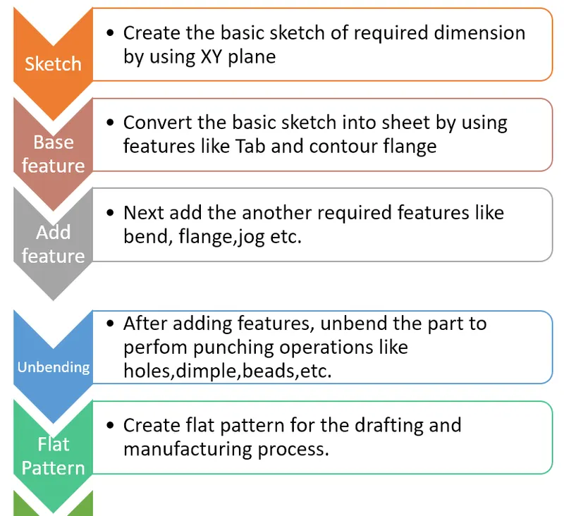
Commands/feature used
- Sketch
- Tab/Sketch – Rectangle
- Cutout/Sketch – Rectangle
- Bend/Sketch - Two mirror lines from center
- Flange
- Break corner
- Unbend
- Hole/Sketch - Circle and mirror
- Dimple/Sketch-line, mirror, Studio spline, and move curve
- Bead/Sketch – Circle
- Rebend
- Flatout feature
- Finally Drafting in A4 sheet
Description of the command used -
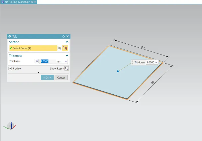
- Tab – Tab is the command used to convert 2D sketch into thin sheet. Global value of the sheet is 3mm. But in this project we consider 1mm thick sheet. Tab given is 1mm. Tab feature is shown in fig below
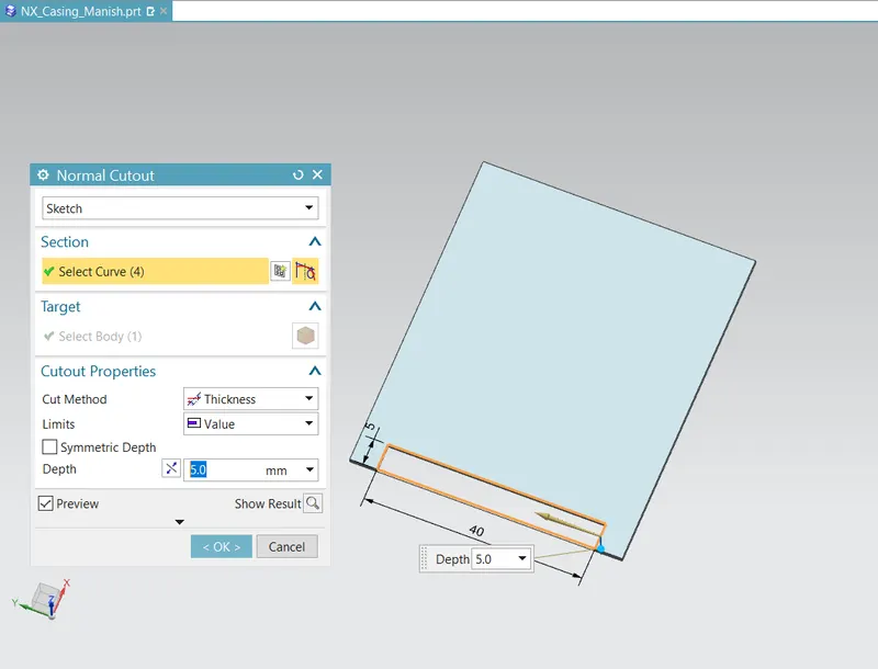
- Normal Cutout -
When it is necessary to remove material from a sheet metal part, you must use the NormalCutout command. First, draw a sketch, and then activate the Normal Cutout command (Onthe ribbon, click Home > Feature > Normal Cutout). Click on the sketch and select theextent type from Cutout Properties > Limits. Type-in a value in the Depth box in case theLimits is set to Value. On the dialog, click OK to create the cutout.
-
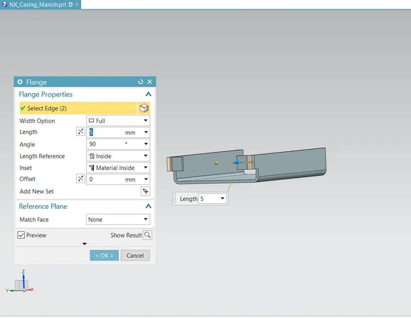
FlangeThe second feature after creating a tab is flange. You can create this feature along an edgeor multiple edges of a sheet metal part. In order to create a flange, all you need is to activatethe Flange command (On the ribbon, click Home > Bend > Flange), and then click an edgeof the tab feature.
-
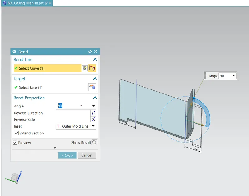
BendIn addition to adding flanges and contour flanges, you can also bend a flat sheet using theBend command. Activate the Bend command (click Home > Bend > More > Bend on theribbon) and click on the face to bend. Draw a sketch line on the flat sheet and click Fin-ish on the ribbon. The flat sheet bends along the sketch line. On the Bend dialog, click theReverse Side button to flip the bend side. Type-in a value in the Angle box to change thefolding angle.
-
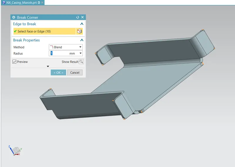
Break CornerThe Break Corner command rounds or chamfers the sharp corners of a sheet metal part.Activate this command (click Home > Corner > Break Corner on the ribbon) and clickon the corner edges of the sheet metal part. If you want to break all the corners of the sheetmetal part, then drag a window across the geometry. This will select all the corners of thesheet metal part.
-
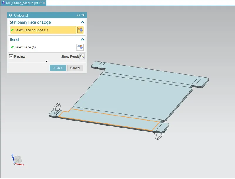
UnbendNX allows you to create dimple across bends. First, you have to unbend the sheet metal partusing the Unbend command. Activate the Unbend command (On the ribbon, click Home> Form > Unbend) and click on the face to remain stationary. Click on the bend and clickOK to unbend the sheet metal part.
-
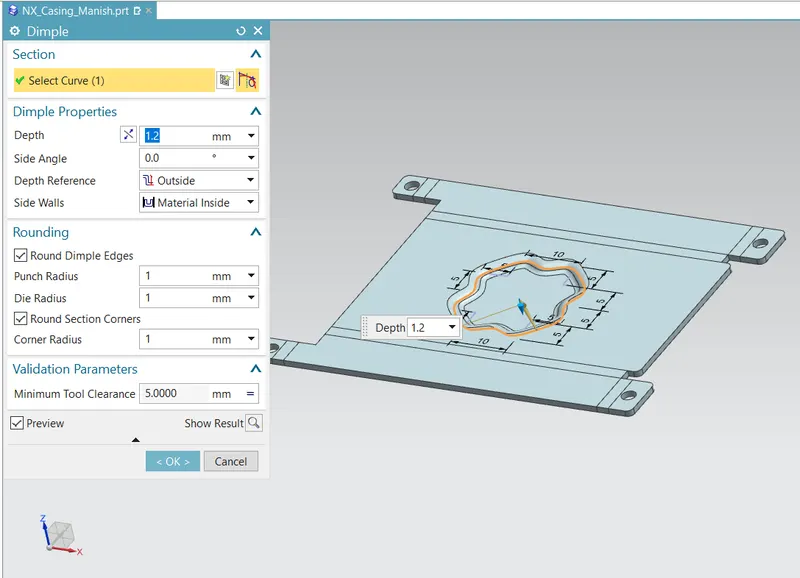
DimpleThe Dimple command adds a dimple to a flat sheet by deforming it. Activate the Dimplecommand (click Home > Punch > Dimple on the ribbon) and click on the face to adddimple. Draw a closed sketch and click Finish on the ribbon. A dimple shape appears onthe sketch region. On the Dimple dialog, click the Reverse Direction button to change thedimple direction. Type-in a value in the Depth box to define the depth of the dimple feature.
-
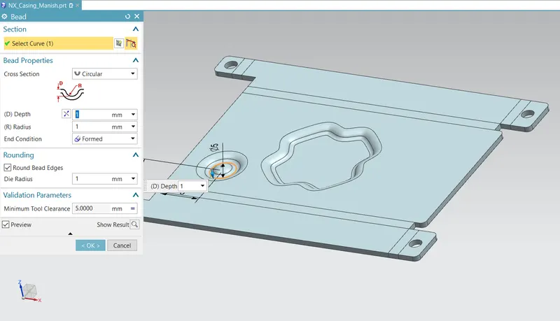
BeadThe Bead command creates a bead feature, which stiffens the sheet metal part. In order tocreate a bead feature, first you must have a sketch, which defines the bead size and shape. Ifthe sketch is having curved edges, then ensure that they are tangent continuous. Activate theBead command (click Home > Punch > Bead on the ribbon) and click on the sketch. Onthe Bead dialog, click the Reverse Direction button to flip the bead feature.
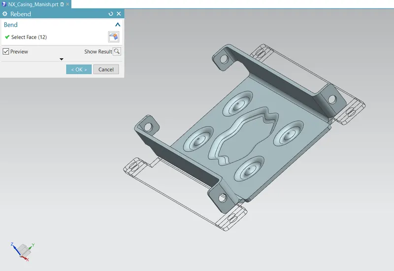
- Rebend
Now, activate the Rebend command (On the ribbon, click Home > Form > Rebend) andclick on the bend. On the Rebend dialog, click OK to rebend the sheet metal part.
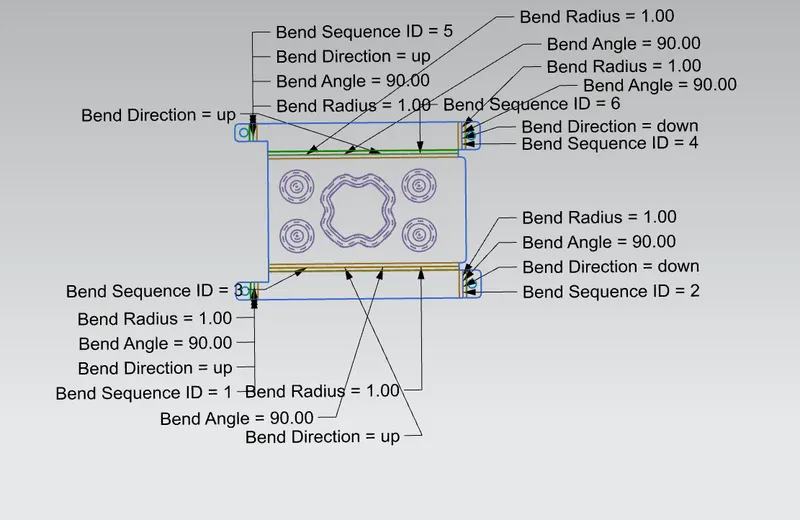
- Flat pattern - This feature is used to create an instances of the flat shape and size of the sheet metal that required to create final part.
- Drafting of Part
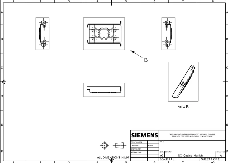
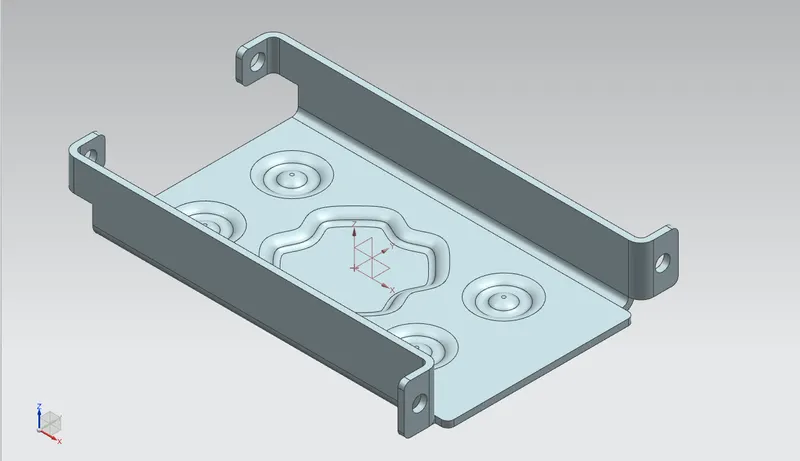
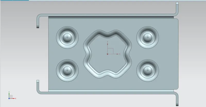
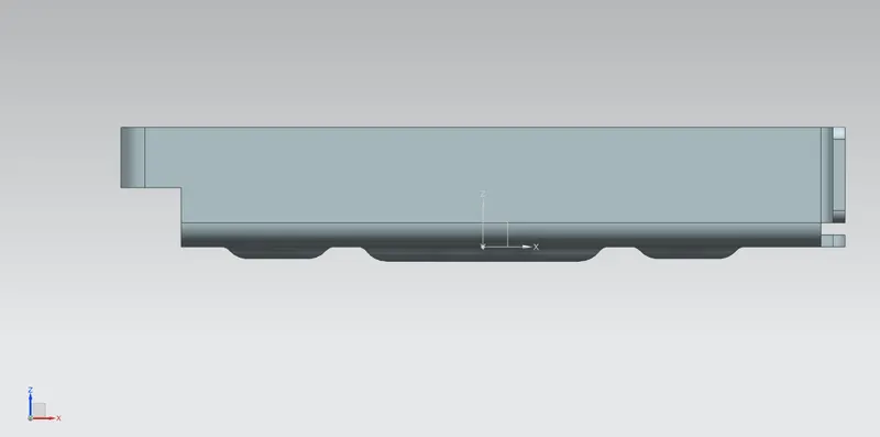
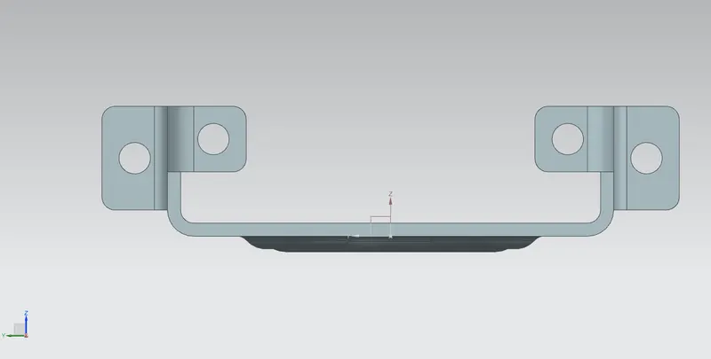
- Various Views of Casing Part-
- Isometric Views
- Top View
- Front View
- Left Side View
- Conclusion-
Finally with this project of Sheet metal casing in NX CAD basic understanding about GUI and sheet metal application developed.Also this project teach us basic approach to sheet metal modelling and utilization of command.