Advanced Sheet Metal Design Using NX Cad Challenge_5_Odd Shaped Enclosure
Advance Sheet Metal Design of Odd Shape Enclosure by Using NX CAD
Objective –
- Design the odd shape enclosure by using NX Cad
- To learn various features, use in designing of odd shape enclosure
Introduction - Sheet metal is metal formed by an industrial process into thin, flat pieces. Sheet metal is one of the fundamental forms used in metalworking, and it can be cut and bent into a variety of shapes. Countless everyday objects are fabricated from sheet metal. Thicknesses can vary significantly; extremely thin sheets are considered foil or leaf, and pieces thicker than 6 mm (0.25 in) are considered plate steel or "structural steel".
Sheet metal is used in automobile and truck (lorry) bodies, airplane fuselages and wings, medical tables, roofs for buildings (architecture), and many other applications.
Design Methodology –
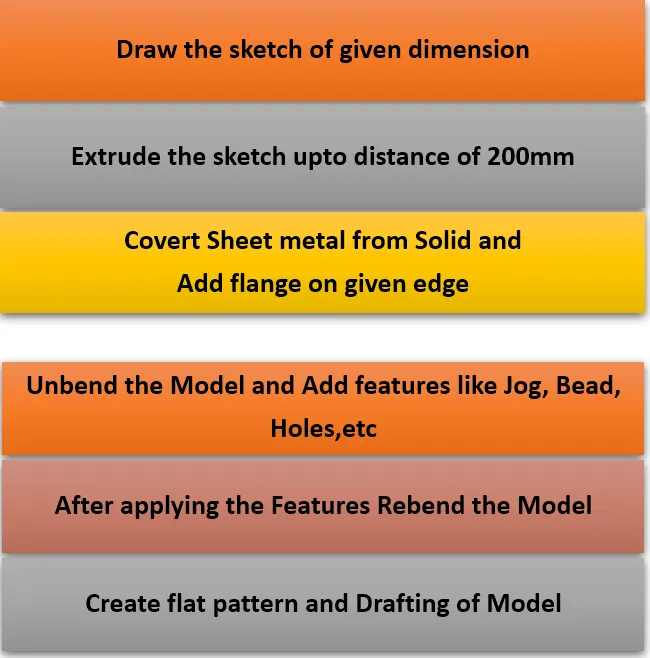
Description of commands:
Tab- The tab is a basic type of sheet metal feature. To create a tab, create a closed sketch on a plane and activate the Tab command (On the ribbon, click Home > Basic > Tab). Click on the sketch, and then click OK on the Tab dialog. In this project we create 200*150 rectangular tab with 1mm thickness.
Flanges- The second feature after creating a tab is flange. You can create this feature along an edge or multiple edges of a sheet metal part. In order to create a flange, all you need is to activate the Flange command (On the ribbon, click Home > Bend > Flange), and then click an edge of the tab feature. The flange preview appears on the selected face. Click the arrow and drag the pointer to change the length of the flange.
Sheet Metal from Solid - The Sheet Metal from Solid command creates a sheet metal part from a set of planar faces of a solid body. First, create a solid body using the Extrude command, and then activate the Sheet Metal from Solid command. Click on the planar faces of the solid body, which connect each other. The Sheet Metal from Solid message appears. Click OK to preview the sheet metal.
Jog - The Jog command adds a jog or offset to a flat sheet. Activate the Jog command and click on a face to add the jog. Draw a line defining the location of the jog, and then click Finish on the ribbon. A preview of the jog feature appears. Type-in a value in the Height box to define the jog height. On the Jog dialog, click the Reverse Side button to flip the jog side. Click the Reverse Direction to reverse the jog direction.
Beads- The Bead command creates a bead feature, which stiffens the sheet metal part. In order to create a bead feature, first you must have a sketch, which defines the bead size and shape. If the sketch is having curved edges, then ensure that they are tangent continuous. Activate the Bead command (click Home > Punch > Bead on the ribbon) and click on the sketch. On the Bead dialog, click the Reverse Direction button to flip the bead feature.
Hole – It is the feature used to create throughout circular cut out of required diameter on body.
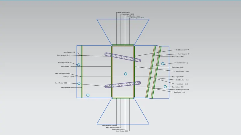
Flat Pattern- This feature is used to create an instance of the flat shape and size of the sheet metal that required to create final part.
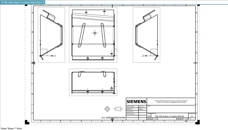
Drafting - After creating 3D model of sheet metal box assembly it can be converted in 2D drawing on sheet for the easy interpretation of model.
Dimensional Views
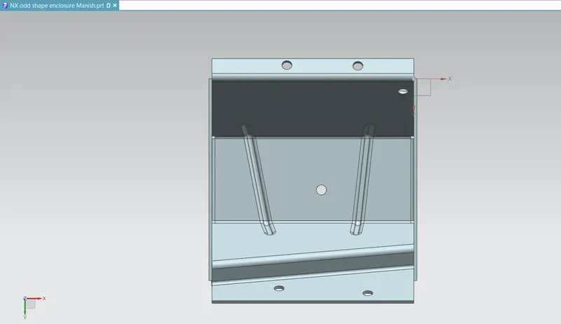
1. Top View
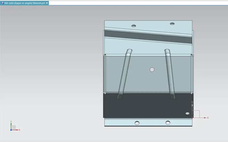
2. Isometric View

3. Left view
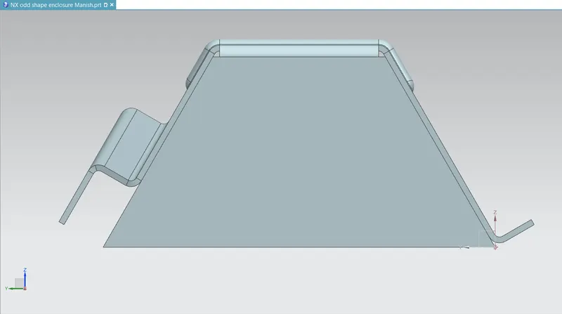
4. Front View
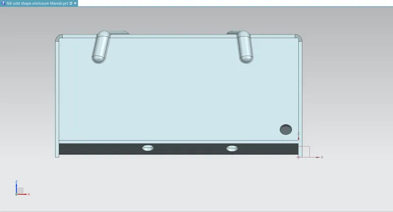
5. Bottom view
6. Flat Pattern
7. Drafting
Conclusion – Successfully design the odd shape enclosure and learn the features use in NX Cad.