Photo Realistic Rendering
Modeling and Rendering of American Chopper in Solidworks 2019
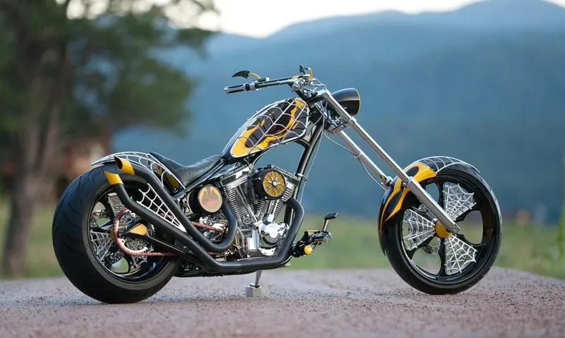
Fig 1. Reference image of American Chopper
Drive Link of Project:
https://drive.google.com/file/d/1s-_-nJQ6j8OaZebtrMVf-8wJAws9W--t/view?usp=sharing
Objective:
- To create 3D Modelling of the different parts of the American chopper using Solidworks.
- Assembly of all the parts.
- Creating photorealistic view and render American chopper by using Photo view 360 and Solidworks visualize.
Introduction:
American Chopper is an American reality television series that airs on Discovery Channel, produced by Pilgrim Films & Television. The series centers on Paul Teutul Sr. and his son Paul Teutul Jr. who manufacture custom chopper-style motorcycles.
SolidWorks is a solid modeling computer-aided design and computer-aided engineering computer program published by Dassault Systems, that runs primarily on Microsoft Windows. The software is used for design and building of 3D mechanical, electrical, and software elements.
Here In this project, I use Solidworks 2019 to create 3D modelling of chopper parts, assembling and Solidworks visualize for rendering.
Individual Parts to Design:
- Transmission Belt
- Kickstand
- Chain
- Front Fender
- Rear Fender
- Oil Tank
- Pedal
- Front Wheel
- Rear Wheel
- Front Fork
- Chassis
- Engine
- Gas Tank
Methodology used in designing of Chopper explain with flow chart:
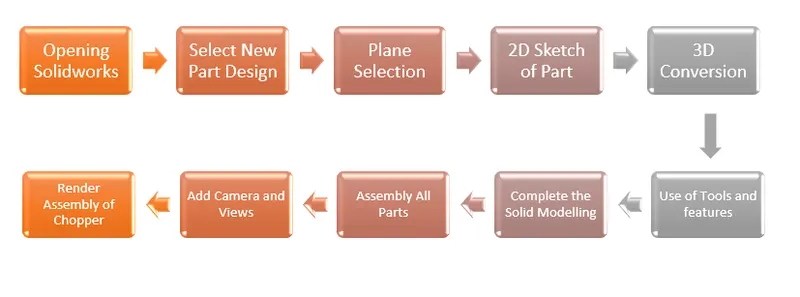
Tools and Features used during Modelling of all Parts:
- Sketch – It is the fully defined 2D drawing of the part. In which many entities are available to complete the drawing like line, spline, circle, rectangle, corner fillet, etc. In which dimension tool is very important due to that drawing get fully defined. In which we can provide linear as well as angular dimensions and get fully defined sketch.
- Extruded Boss/Base – This feature is used to convert the 2D sketch into 3D model. It provides thickness to the part in X as well as Y direction also provide offset extrude required distance.
- Extruded Cut – It is the feature used to remove material from solid part in desired directions and also in both the directions.
- Revolved Boss/Base – It is used to revolve the sketch around the reference axis or plane to form cylindrical like structure.
- Revolved Cut – This feature cuts the solid model by revolving a sketch profile around axis or plane.
- Sweep Boss/Base – It is used to sweep a closed profile along an open or closed path to create solid feature and forms pipe like structure.
- Lofted Boss/Base – It is used to add material between two or more profiles to create solid feature.
- Boundary Boss/Base – Adds material between profiles in two directions or in two boundaries to create solid feature.
- Fillet – Creates a rounded internal or external face along one or more edges in solid feature.
- Chamfer – Creates a sloped or angled corner or edge it may be internal or external edge.
- Linear Pattern - Patterns features, faces and bodies in one or two linear directions.
- Circular Pattern – Patterns features faces and bodies in one or more in circular direction.
- Shell – It removes material from a solid body to create a thin-walled feature.
- Mirror – Mirror features, faces and bodies about aa face or plane or a axis.
- Dome – Adds one or more dome to selected planar or non-planar faces.
- Split – It creates multiple bodies from a single body. It also creates the bodies in the existing part or in separate parts.
- Combine – It is used to combine the two bodies or faces intersecting each other convert into single surface.
- Knit surface - Use the Knit Surface tool to combine two or more faces and surfaces into one.
- Projected Curve – Projected curve is type of curve used in Solidworks which is used to create or project on to a face of the model or to create a 3D curve in Solidworks.
- Mate - Mates create geometric relationships between assembly components. As you add mates, you define the allowable directions of linear or rotational motion of the components. You can move a component within its degrees of freedom, visualizing the assembly's behaviour
Parts and Features used to Create:
- Transmission Belt
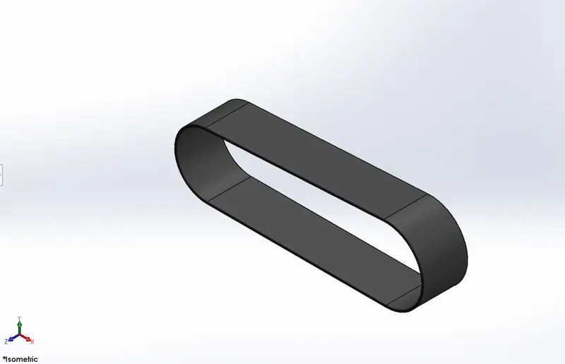
Fig. 2 Isometric View of Transmission Belt
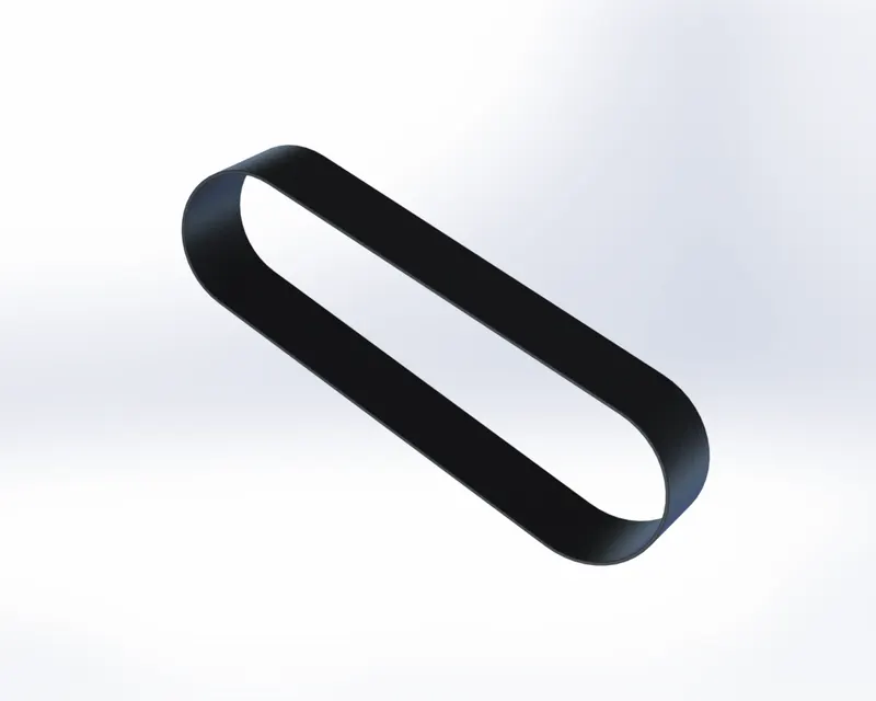
Fig. 3 Rendered View of Transmission Belt
Stepwise Features Applied on Modeling of Transmission Belt:
- Sketch
- Offset Entities
- Extrude Boss/Base
- Fillet
- Appearance
- Kickstand
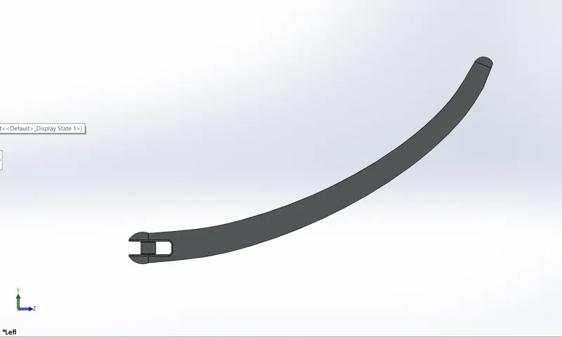
Fig. 4 Isometric View of Kickstand
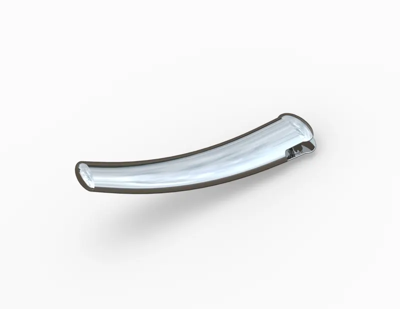
Fig. 5 Rendered View of Kickstand
Stepwise Features Applied on Modeling of Kickstand:
- Sketch
- Extrude Boss/Base
- Lofted Surface
- Extrude Cut
- Split
- Dome
- Fillet
- Appearance
- Chain
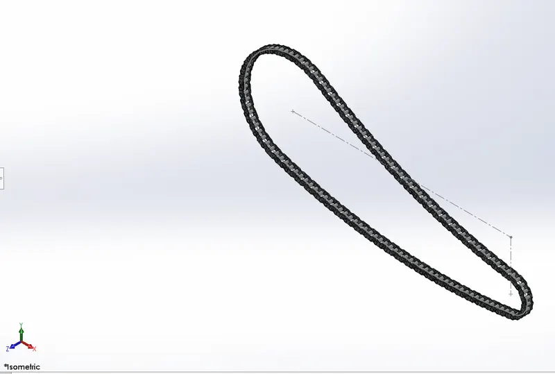
Fig. 6 Isometric View of Chain
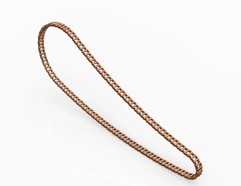
Fig. 7 Rendered View of Chain
Stepwise Features Applied on Modeling of Chain:
- Sketch
- Sketch Blocks
- Extrude Boss/Base
- Curve Driven Pattern
- Mirror
- Appearance
- Front Fender
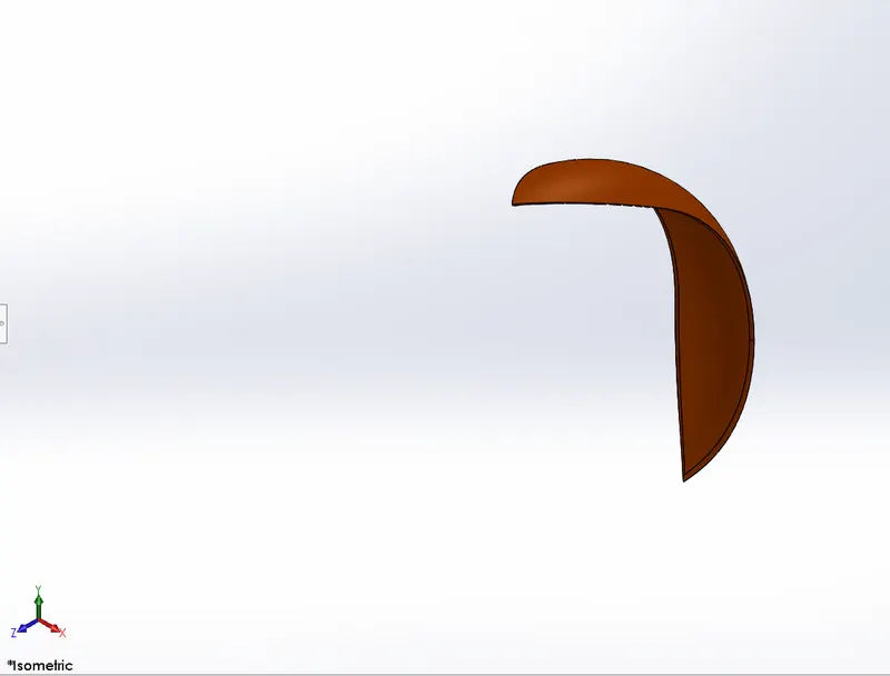
Fig. 8 Isometric View of Front Fender
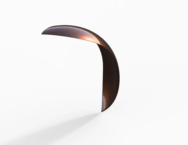
Fig. 9 Rendered View of Front Fender
Stepwise Features Applied on Modeling of Front Fender:
- Sketch
- Offset Entities
- Revolved Boss/Base
- Split
- Appearance
- Rear Fender
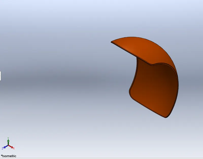
Fig. 10 Isometric View of Rear Fender
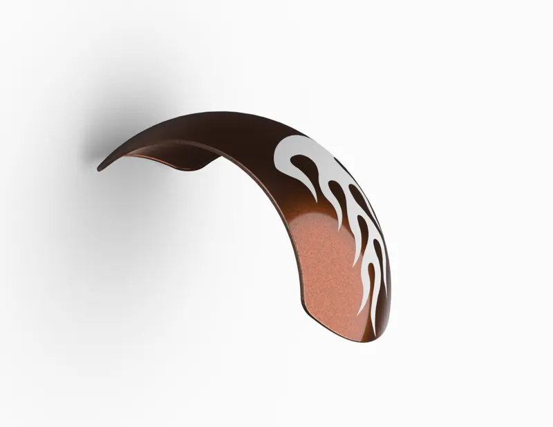
Fig. 11 Rendered View of Rear Fender
Stepwise Features Applied on Modeling of Rear Fender:
- Sketch
- Offset Entities
- Trim
- Revolved Boss/Base
- Split
- Appearance
- Add Decals
- Oil Tank
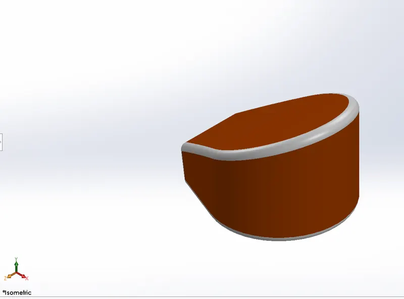
Fig. 12 Isometric View of Oil Tank
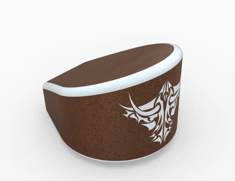
Fig. 13 Rendered View of Oil Tank
Stepwise Features Applied on Modeling of Oil Tank:
- Sketch
- Boss Extrude
- Combine
- Fillet
- Shell
- Appearance
- Add Decals
- Pedal
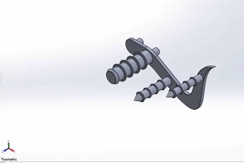
Fig. 14 Isometric View of Pedal
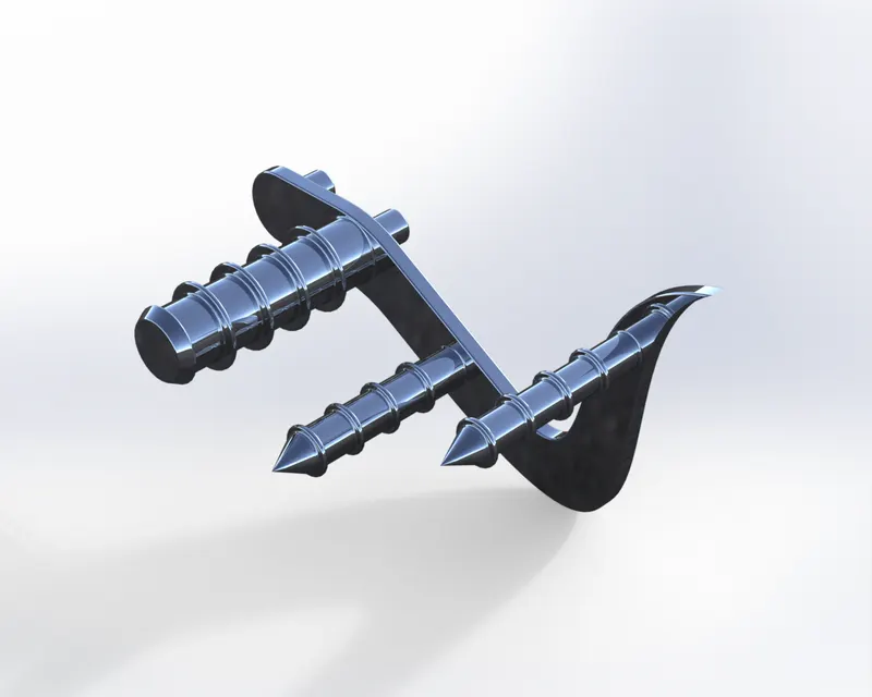
Fig. 15 Rendered View of Pedal
Stepwise Features Applied on Modeling of Pedal:
- Sketch
- Extrude Boss/Base
- Fillet
- Linear Pattern
- Dome
- Chamfer
- Appearance
- Front Wheel
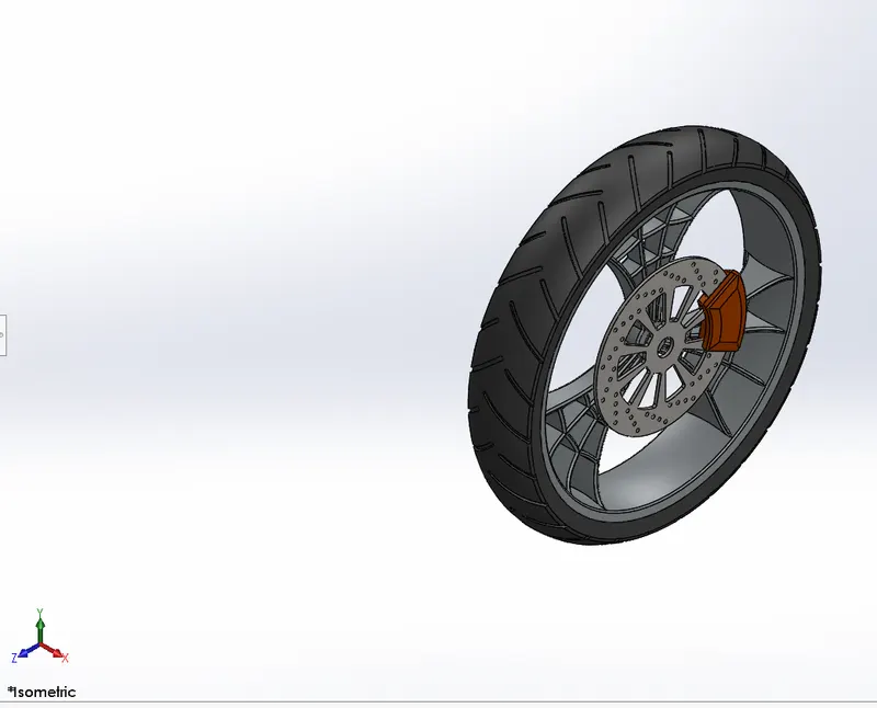
Fig. 16 Isometric View of Front Wheel
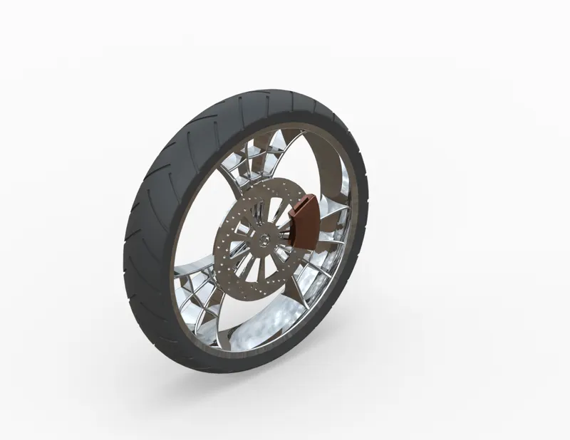
Fig. 17 Rendered View of Front Wheel
Stepwise Features Applied on Modeling of Front Wheel:
- Sketch
- Revolved Boss/Base
- Trim
- Sketch Fillet
- Boss Extrude
- Revolve Cut
- Linear Pattern
- Chamfer
- Cut Extrude
- Circular Pattern
- Appearance
- Rear Wheel
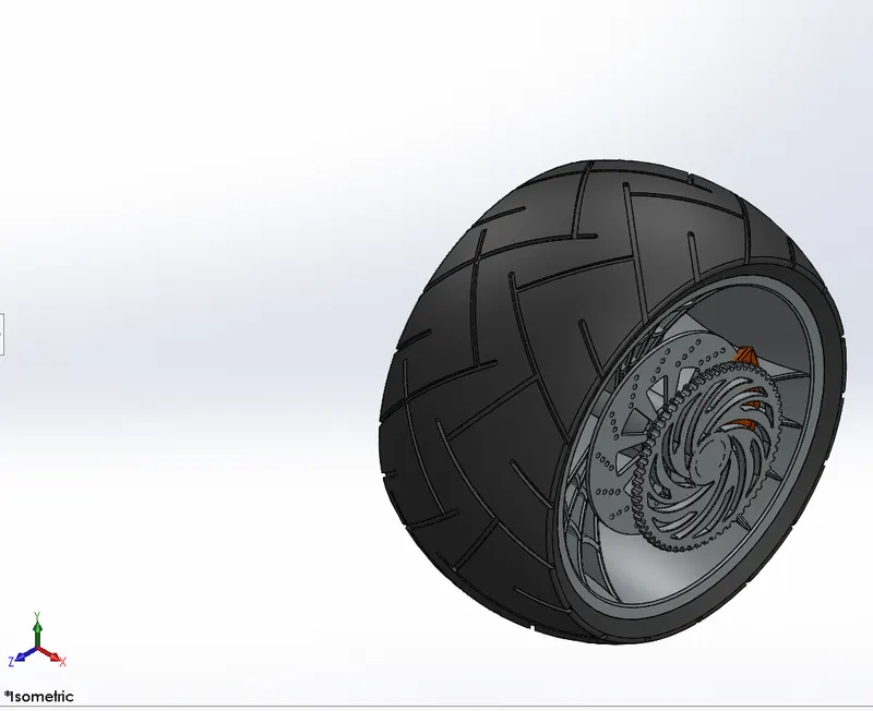
Fig. 18 Isometric View of Rear Wheel
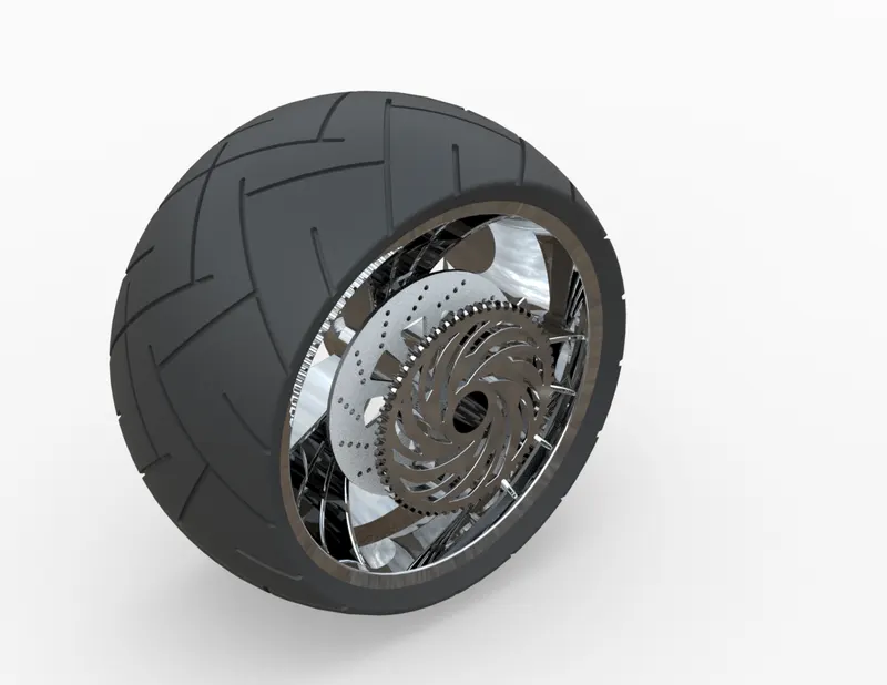
Fig. 19 Rendered View of Rear Wheel
Stepwise Features Applied on Modeling of Rear Wheel:
- Sketch
- Revolved Boss/Base
- Trim
- Sketch Fillet
- Extrude Boss/Base
- Reference plane
- Revolved Cut
- Linear Patter
- Chamfer
- Fillet
- Extrude Cut
- Circular Pattern
- Appearance
- Front Fork
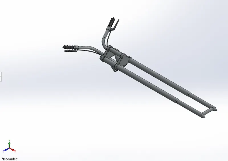
Fig. 20 Isometric View of Front Fork
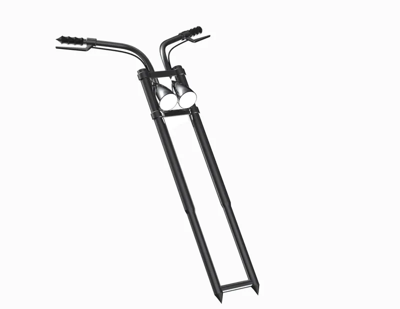
Fig. 21 Rendered View of Front Fork
Stepwise Features Applied on Modeling of Front Fork:
- Sketch
- Extrude Boss
- Trim
- Revolved Boss
- Split
- Move/Copy Bodies
- Dome
- Mirror
- Combine
- Projected Curve
- Sweep
- Appearances
- Chassis
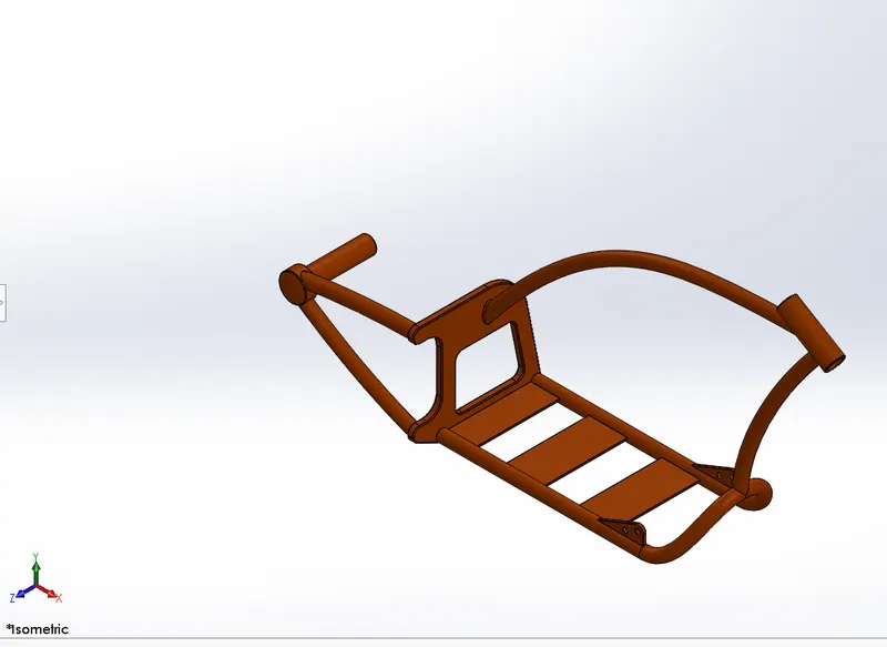
Fig. 22 Isometric View of Chassis
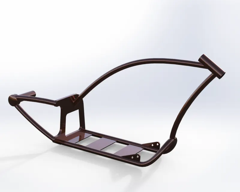
Fig. 23 Rendered View of Chassis
Stepwise Features Applied on Modeling of Chassis:
- Sketch
- Offset Entities
- Convert Entities
- Project Curve
- Trim
- Sweep
- Split
- Revolved Boss
- Cut Extrude
- Fillet
- Combine
- Appearance
- Engine
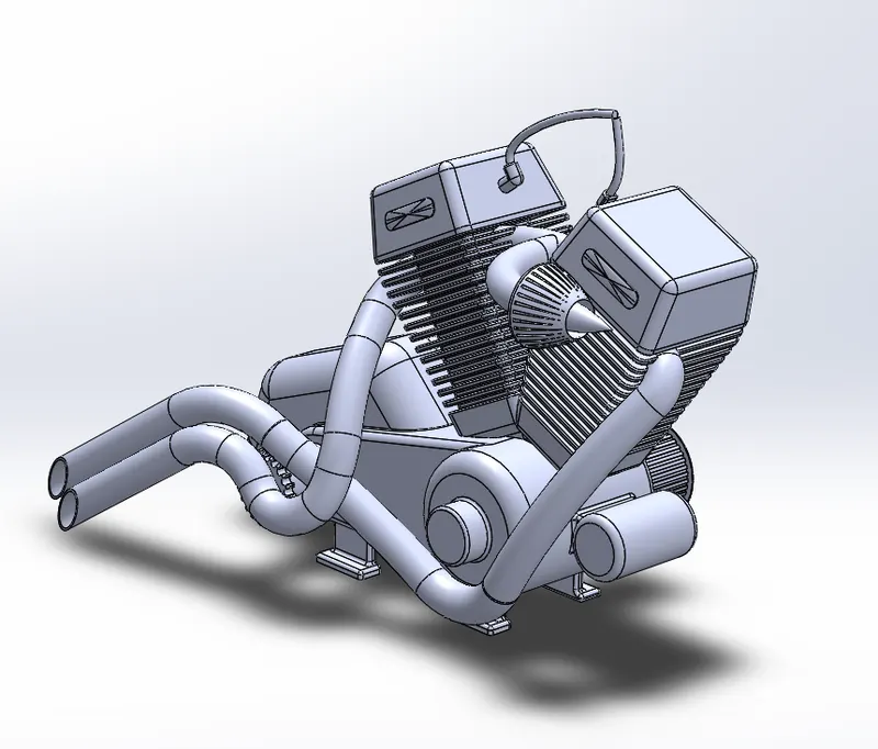
Fig. 24 Isometric View of Engine
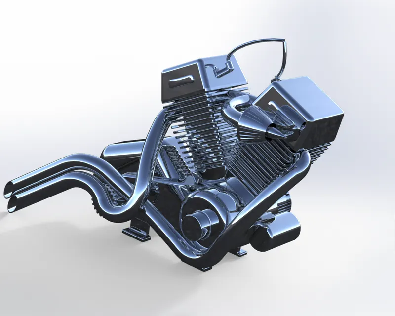
Fig. 25 Rendered View of Engine
Stepwise Features Applied on Modeling of Engine:
- Sketch
- Trim
- Revolve Boss
- Extrude Cut
- Offset
- Dome
- Fillet
- Project Curve
- Composite Curve
- Sweep
- Mirror
- Circular Pattern
- Split
- Appearance
- Gas Tank
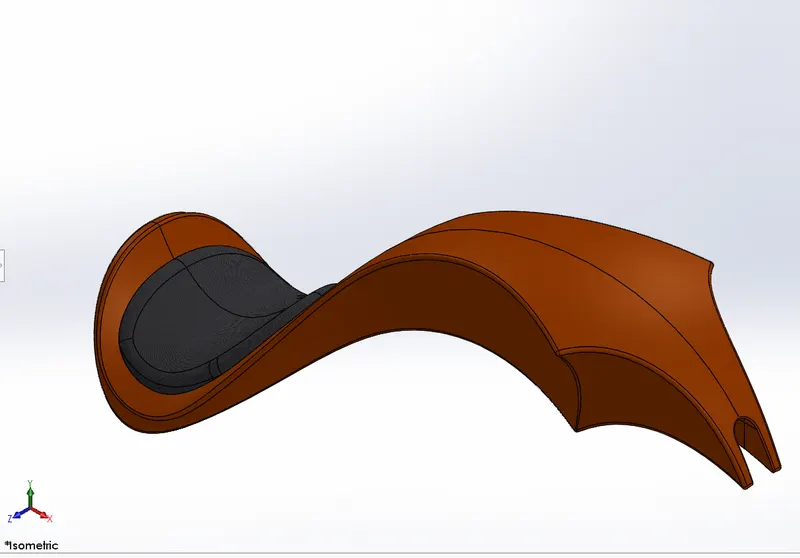
Fig. 26 Isometric View of Gas Tank
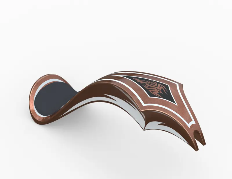
Fig. 27 Rendered View of Gas Tank
Stepwise Features Applied on Modeling of Gas Tank:
- Sketch
- Trim
- Projected Curve
- Sweep Surface
- Loft Surface
- Boundary Surface
- Surface Trim
- Surface Knit
- Sweep Cut
- Fillet
- Appearances
Assembly of American Chopper:
You can build complex assemblies consisting of many components, which can be parts or other assemblies, called subassemblies. For most operations, the behaviour of components is the same for both types. Adding a component to an assembly creates a link between the assembly and the component.
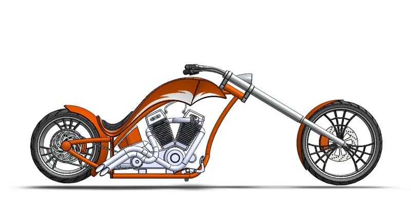
Fig. 28 Front View of American Chopper
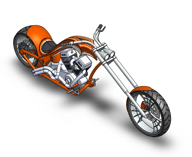
Fig. 29 Isometric View of American Chopper
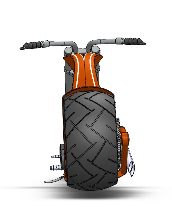
Fig. 30 Left Side View
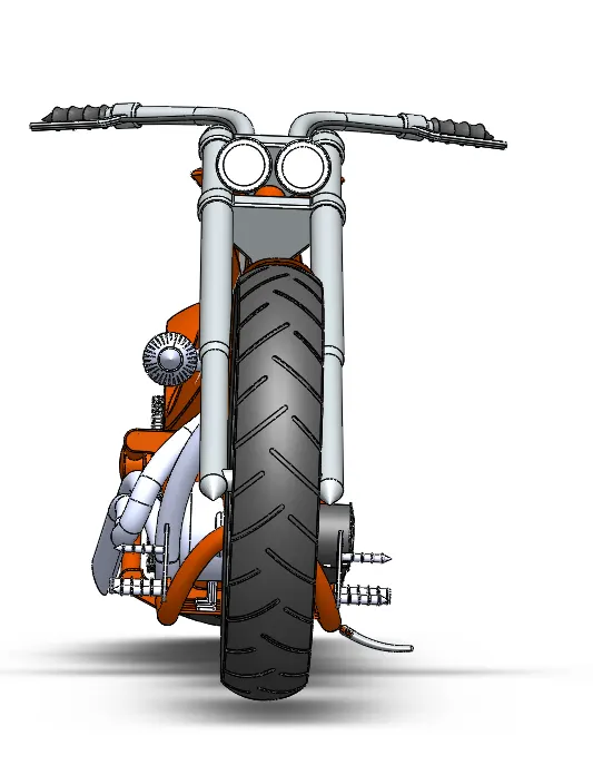
Fig. 31 Right Side View
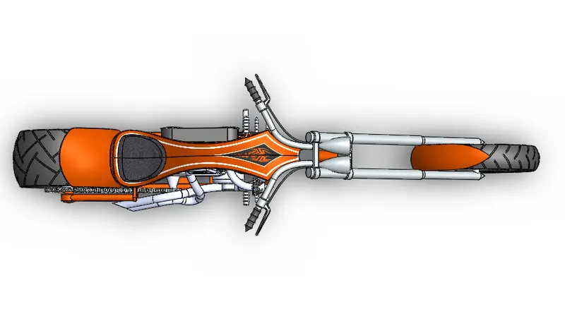
Fig. 32 Top View
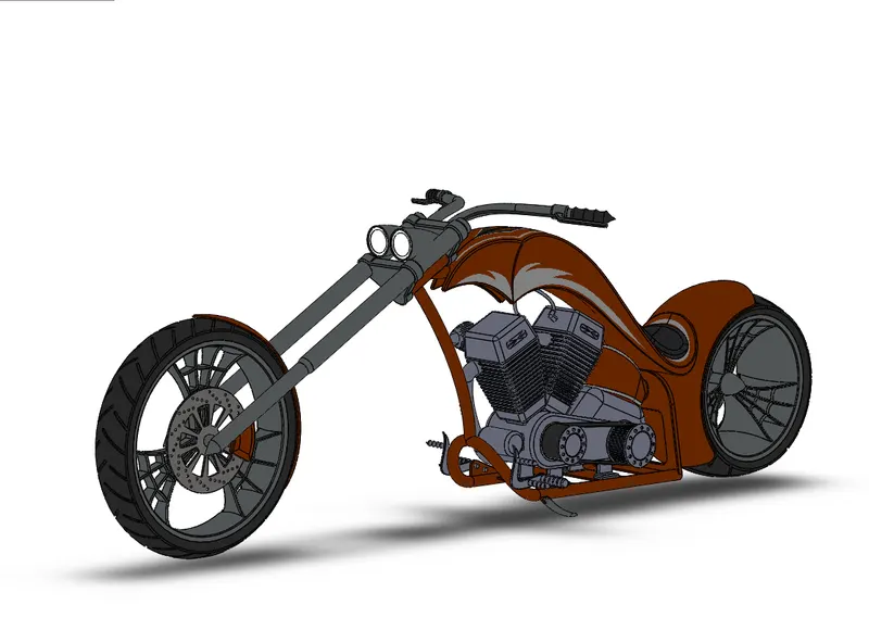
Fig. 33 Camera View
Rendering of American Chopper
It is the photorealistic view of American Chopper by Using Photo view 360 and Solidworks Visualize.
- Load your Model
- Apply Appearances to your model through Paint
- Apply a Scene
- Apply Cameras
- Render it out
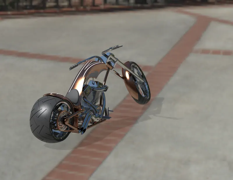
Fig. 34 Rendered View
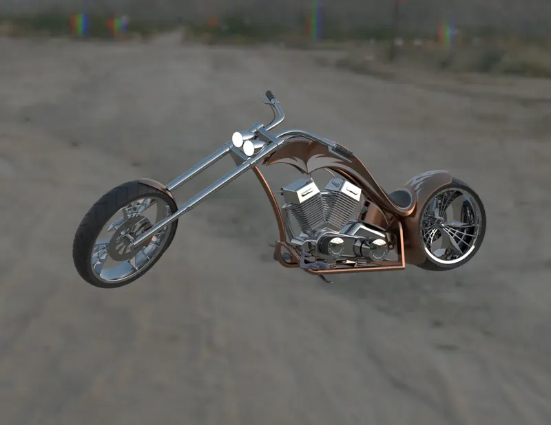
Fig. 35 Rendered View
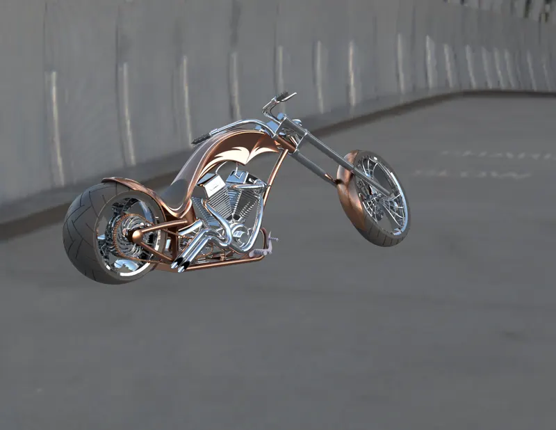
Fig. 36 Rendered View
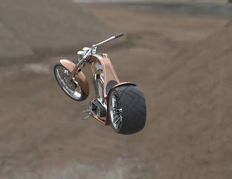
Fig. 37 Rendered View
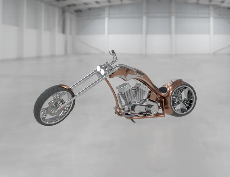
Fig. 38 Rendered View
Conclusion:
- All the Parts of American Chopper are Modeled by Using Solidworks
- All the solid parts are Assembled successfully using Solidworks
- Rendering of the assembly is done successfully using photo view 360 and Solidworks Visualize.