Advanced Sheet Metal Design Using NX Cad Challenge_2_Box Assembly
DESIGN BOX ASSEMBLY BY USING SIEMENS NX 12
Objective: Learn to design a sheet metal Box Assembly in industrial manner by using Siemens NX.
INTRODUCTION:
Sheet metal parts are widely used in machinery, enclosure, brackets, and automobile due to its various advantages. The parts are normally manufactured with break press. Sheet metal is nothing but the thin sheets made from metal of size ranging from 0.5 to 6mm. In this project I used NX CAD tool for designing the sheet metal bracket. NX CAD is used as design tool in more than 85% of the sheet metal industries.
Design Methodology:
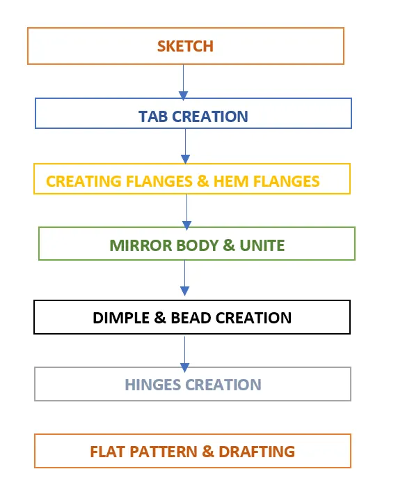
Description of commands:
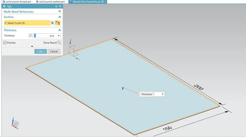
Tab- The tab is a basic type of sheet metal feature. To create a tab, create a closed sketch on a plane and activate the Tab command (On the ribbon, click Home > Basic > Tab). Click on the sketch, and then click OK on the Tab dialog. In this project we create 200*150 rectangular tab with 1mm thickness.
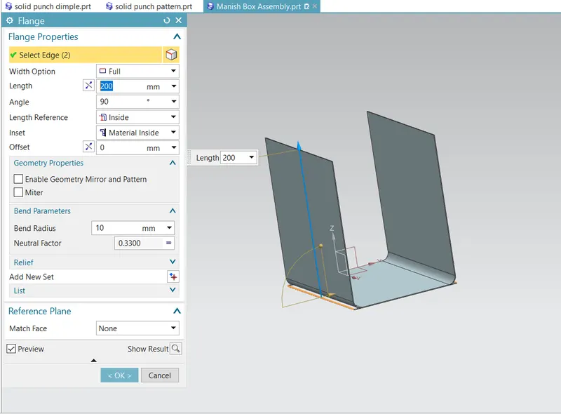
Flanges- The second feature after creating a tab is flange. You can create this feature along an edge or multiple edges of a sheet metal part. In order to create a flange, all you need is to activate the Flange command (On the ribbon, click Home > Bend > Flange), and then click an edge of the tab feature. The flange preview appears on the selected face. Click the arrow and drag the pointer to change the length of the flange.
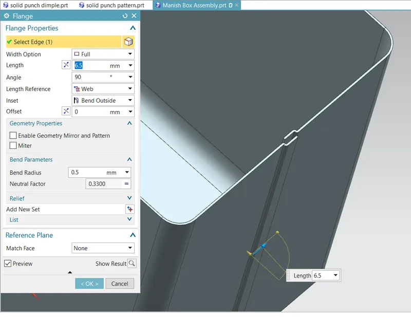
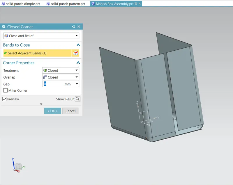
Closed Corner-The Closed Corner command allows you to control the appearance of sheet metal seams. For example, when two flanges meet at a corner, this command allows you to close the gap between them. In addition to that, it applies a corner treatment.
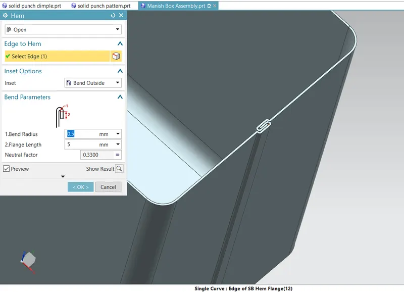
Hems- The Hem command folds an edge of a sheet metal part. To add a hem, activate the Hem command (click Home > Bend > More > Hem on the ribbon) and select the edge you need to fold over.
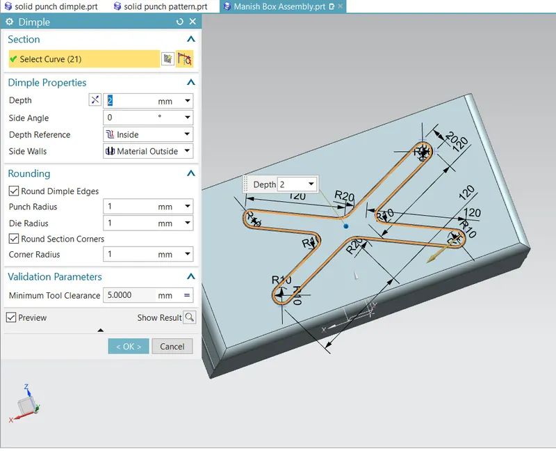
Dimples-The Dimple command adds a dimple to a flat sheet by deforming it. Activate the Dimple command (click Home > Punch > Dimple on the ribbon) and click on the face to add dimple. Draw a closed sketch and click Finish on the ribbon. A dimple shape appears on the sketch region. On the Dimple dialog, click the Reverse Direction button to change the dimple direction. Type-in a value in the Depth box to define the depth of the dimple feature.
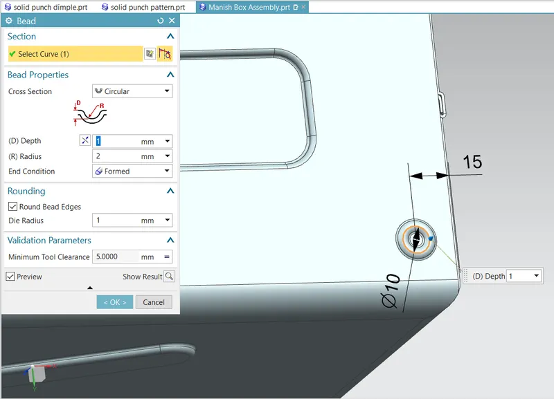
Beads- The Bead command creates a bead feature, which stiffens the sheet metal part. In order to create a bead feature, first you must have a sketch, which defines the bead size and shape. If the sketch is having curved edges, then ensure that they are tangent continuous. Activate the Bead command (click Home > Punch > Bead on the ribbon) and click on the sketch. On the Bead dialog, click the Reverse Direction button to flip the bead feature.
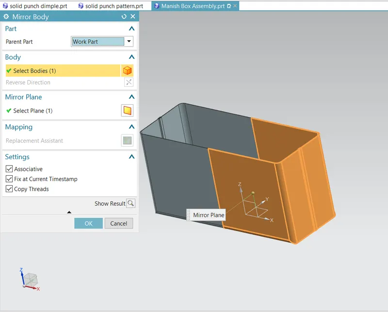
Mirror Feature - After creating half part of the assembly another half part of body can be created by using mirror feature along the YZ plane.
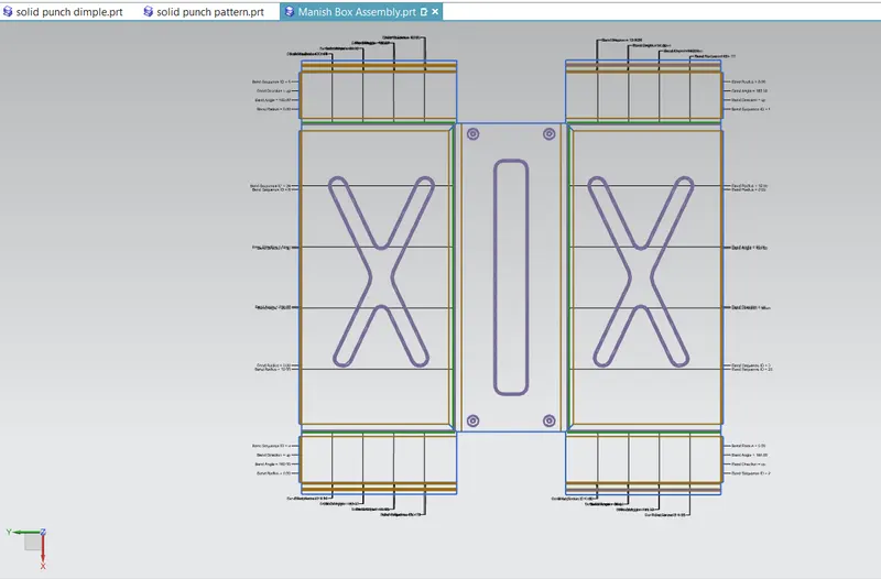
Flat Pattern- This feature is used to create an instance of the flat shape and size of the sheet metal that required to create final part.
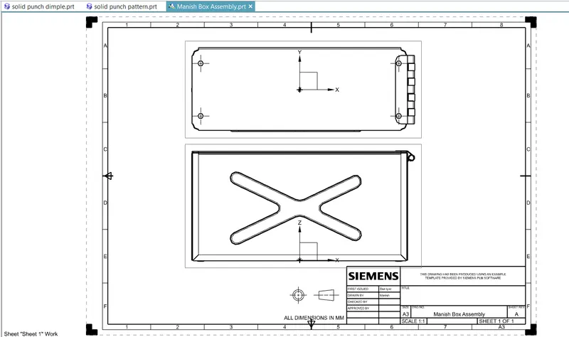
Drafting - After creating 3D model of sheet metal box assembly it can be converted in 2D drawing on sheet for the easy interpretation of model.
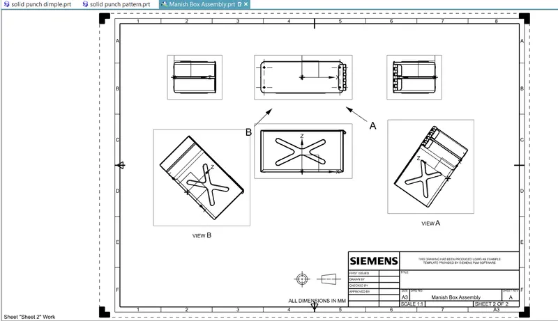
Diffrent Views of Assembly:
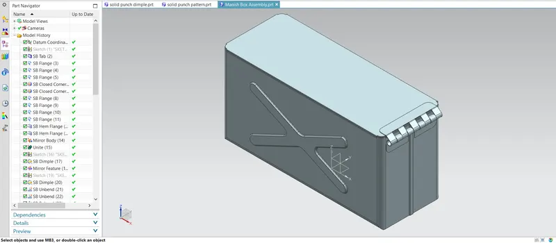
1. Isometric View
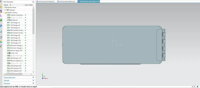
2. Top View
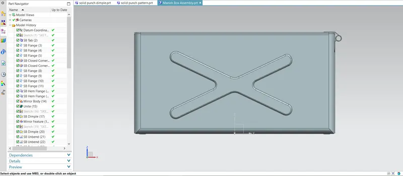
3. Front View
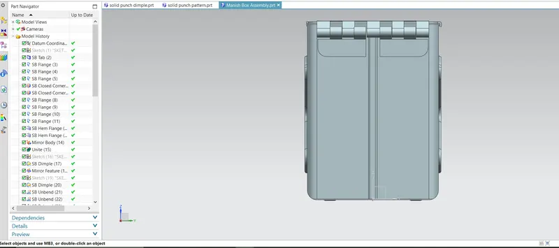
4. Right View
5. Left View
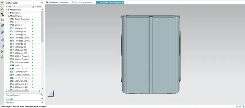
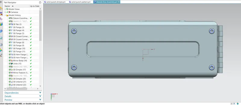
6. Bottom View
Conclusion - Since sucessfully learn to create sheet metal box assembly by using NX 12.