Radar Mast & Final Assembly of Yacht
Modeling and Rendering of Sunseeker Predator Yacht in Solidworks 2019
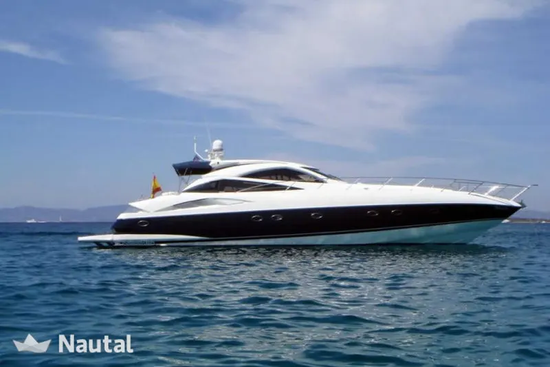
Fig 1. Reference image of Sunseeker Predator Yacht
https://drive.google.com/file/d/10uM8mcc8q8cmLCqXo_3K8pStXhW9MIHg/view?usp=sharing
Objective:
- To create 3D Modelling of the different parts of the Predator Yacht using Solidworks.
- Assembly of all the parts.
- Creating photorealistic view and render Predator Yacht by using Photo view 360 and Solidworks visualize.
Introduction:
A yacht is a sail or power vessel used for pleasure, cruising, or racing. There is no standard definition, so the term applies to such vessels that have a cabin with amenities that accommodate overnight use. To be termed a yacht, as opposed to a boat, such a pleasure vessel is likely to be at least 33 feet (10 m) in length and may have been judged to have good aesthetic qualities.
The Commercial Yacht Code classifies yachts 79 ft (24 m) and over as large. Such yachts typically require a hired crew and have higher construction standards.
Racing yachts are designed to emphasize performance over comfort. Charter yachts are run as a business for profit. As of 2020 there were more than 15,000 yachts of sufficient size to require a professional crew.
Here In this project, I use Solidworks 2019 to create 3D modelling of Yatch parts, assembling and Solidworks visualize for rendering.
Individual Parts to Design:
- Hull
- Propeller
- Radar
- Front Seat
- Middle Seat
- Rear Seat
- Garage Door
- Superstructure
- Radar Mast
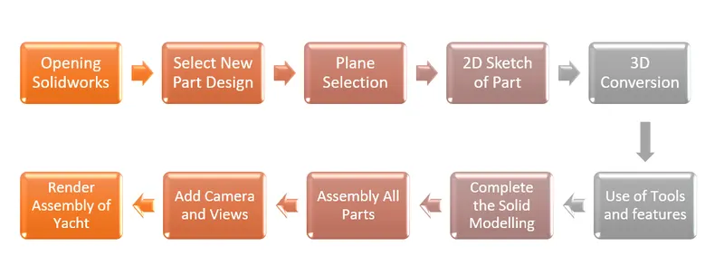
Methodology used in designing of Yatch explain with flow chart:
Tools and Features used during Modelling of all Parts:
- Sketch – It is the fully defined 2D drawing of the part. In which many entities are available to complete the drawing like line, spline, circle, rectangle, corner fillet, etc. In which dimension tool is very important due to that drawing get fully defined. In which we can provide linear as well as angular dimensions and get fully defined sketch.
- Extruded Boss/Base – This feature is used to convert the 2D sketch into 3D model. It provides thickness to the part in X as well as Y direction also provide offset extrude required distance.
- Extruded Cut – It is the feature used to remove material from solid part in desired directions and also in both the directions.
- Revolved Boss/Base – It is used to revolve the sketch around the reference axis or plane to form cylindrical like structure.
- Revolved Cut – This feature cuts the solid model by revolving a sketch profile around axis or plane.
- Sweep Boss/Base – It is used to sweep a closed profile along an open or closed path to create solid feature and forms pipe like structure.
- Lofted Boss/Base – It is used to add material between two or more profiles to create solid feature.
- Boundary Boss/Base – Adds material between profiles in two directions or in two boundaries to create solid feature.
- Fillet – Creates a rounded internal or external face along one or more edges in solid feature.
- Chamfer – Creates a sloped or angled corner or edge it may be internal or external edge.
- Linear Pattern - Patterns features, faces and bodies in one or two linear directions.
- Circular Pattern – Patterns features faces and bodies in one or more in circular direction.
- Shell – It removes material from a solid body to create a thin-walled feature.
- Mirror – Mirror features, faces and bodies about aa face or plane or a axis.
- Dome – Adds one or more dome to selected planar or non-planar faces.
- Split – It creates multiple bodies from a single body. It also creates the bodies in the existing part or in separate parts.
- Combine – It is used to combine the two bodies or faces intersecting each other convert into single surface.
- Knit surface - Use the Knit Surface tool to combine two or more faces and surfaces into one.
- Projected Curve – Projected curve is type of curve used in Solidworks which is used to create or project on to a face of the model or to create a 3D curve in Solidworks.
- Mate - Mates create geometric relationships between assembly components. As you add mates, you define the allowable directions of linear or rotational motion of the components. You can move a component within its degrees of freedom, visualizing the assembly's behaviour.
- Lofted Surface – Creates a lofted surface between two or more sketches or profiles. Specify start and end constraints and also guide curve.
- Extend Surface – Extend one or more edges or faces on a surface based on end condition and extension type.
- Surface Trim – It trims the unwanted surface form the intersection of two surfaces.
- Swept Surface - Create planes for sketching the sweep profile, sweep path, and if necessary, the guide curves.
- Ruled Surface - The Ruled Surface tool_Ruled_Surface_Mold_tools.gif command creates surfaces that extend out in a specified direction from selected edges.
- Helix - create a helix or spiral curve in a part. The curve can be used as a path or guide curve for a swept feature, or a guide curve for a lofted feature
- Delete/Keep Bodies -
Delete- Deletes a face from a surface body, or deletes one or more faces from a solid body to create surfaces.
Delete and Patch-Deletes a face from a surface body or solid body and automatically patches and trims the body.
Delete and Fill- Deletes faces and generates a single face to close any gap.
- Offset Surface – It is used to create offset surface from selected surface with required gap.
Parts and Features used to Create:
- Blue Print Setup – A blueprint can be a reproduction of technical drawing or engineering drawing using a contact print process on light sensitive sheets. Blueprint can be used as guide to make design or follow pattern. They were easier to read and faster to design with the use of blueprint.
- Hull - A hull is the watertight body of a ship or boat. The hull may open at the top (such as a dinghy), or it may be fully or partially covered with a deck. Atop the deck may be a deckhouse and other superstructures, such as a funnel, derrick, or mast.
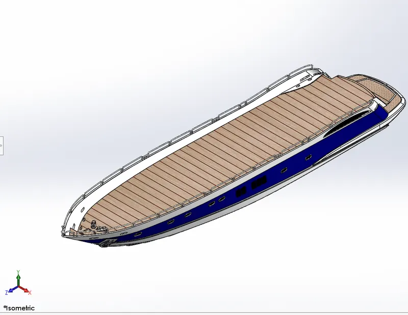
Fig.1 Isometric View of Hull
Stepwise Features Applied on Modeling of Hull:
- Sketch
- Offset Entities
- Extrude Boss/Base
- Fillet
- Project curve
- Lofted surface
- Surface trim
- Extrude Surface
- Knit surface
- Filled surface
- Chamfer
- Swept boss
- Revolved boss
- Dome
- Helix
- Linear pattern
- Split Body
- Mirror
- Appearance
- Propeller - A propeller is a device with a rotating hub and radiating blades that are set at a pitch to form a helical spiral, that, when rotated, performs an action which is similar to Archimedes' screw. It transforms rotational power into linear thrust by acting upon a working fluid, such as water or air.
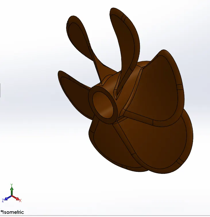
Fig.2 Isometric View of Propeller
Stepwise Features Applied on Modeling of Propeller:
- Sketch
- Lofted Surface
- Extrude Cut
- Revolve
- Circular pattern
- Fillet
- Appearance
- Radar - Radar, electromagnetic sensor used for detecting, locating, tracking, and recognizing objects of various kinds at considerable distances. It operates by transmitting electromagnetic energy toward objects, commonly referred to as targets, and observing the echoes returned from them.
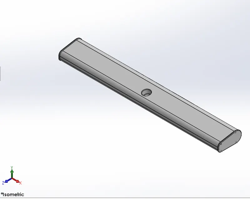
Fig.3 Isometric View of Radar
Stepwise Features Applied on Modeling of Radar:
- Sketch
- Extrude Boss/Base
- Extrude Cut
- Fillet
- Appearance
- Front Seat -
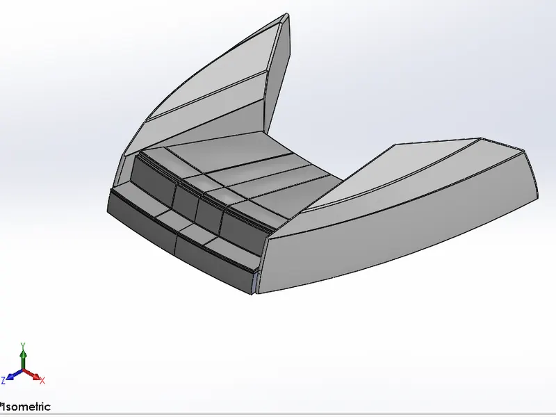
Fig.4 Isometric View of Front Seat
Stepwise Features Applied on Modeling of Front Seat:
- Sketch
- Offset Entities
- Plane
- Sweep
- Surface loft
- Surface trim
- Extrude cut
- Revolve
- Knit surface
- Fill surface
- Dome
- Mirror
- Chamfer
- Fillet
- Appearance
- Rear Seat
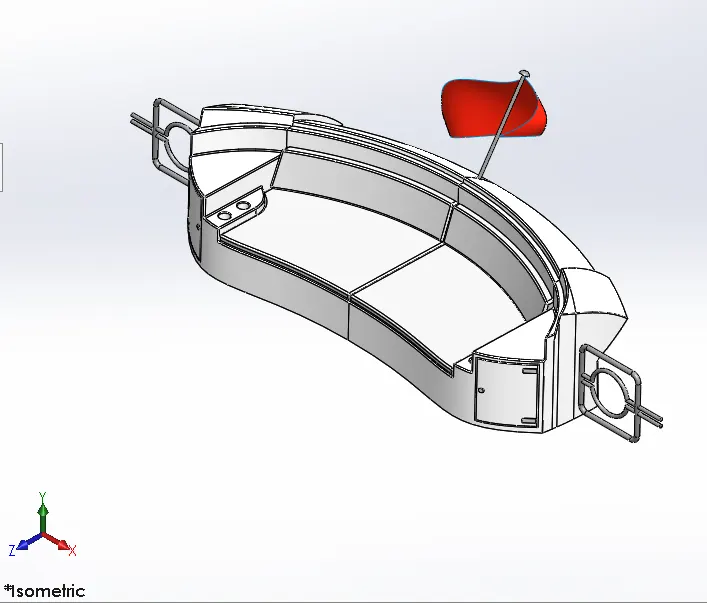
Fig.5 Isometric View of Rear Seat
Stepwise Features Applied on Modeling of Rear Seat:
- Sketch
- Offset Entities
- Surface Loft
- Extrude Surface
- Offset Surface
- Surface trim
- Sweep
- Ruled surface
- Extend surface
- Knit surface
- Chamfer
- Fillet
- Extrude cut
- Mirror
- Appearance
- Middle Seat
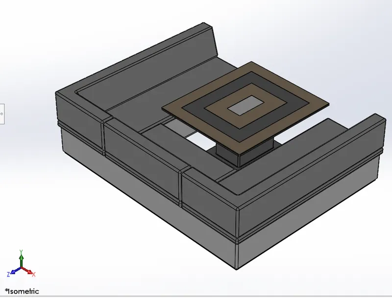
Fig.6 Isometric View of Middle Seat
Stepwise Features Applied on Modeling of Middle Seat:
- Sketch
- Extrude boss
- Offset entities
- Extrude cut
- Mirror
- Chamfer
- Fillet
- Appearance
- Garage Door
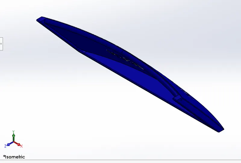
Fig.7 Isometric View of Garage Door
Stepwise Features Applied on Modeling of Garage Door:
- Extrude cut
- Mirror
- Shell
- Fillet
- Appearance
- Superstructure -
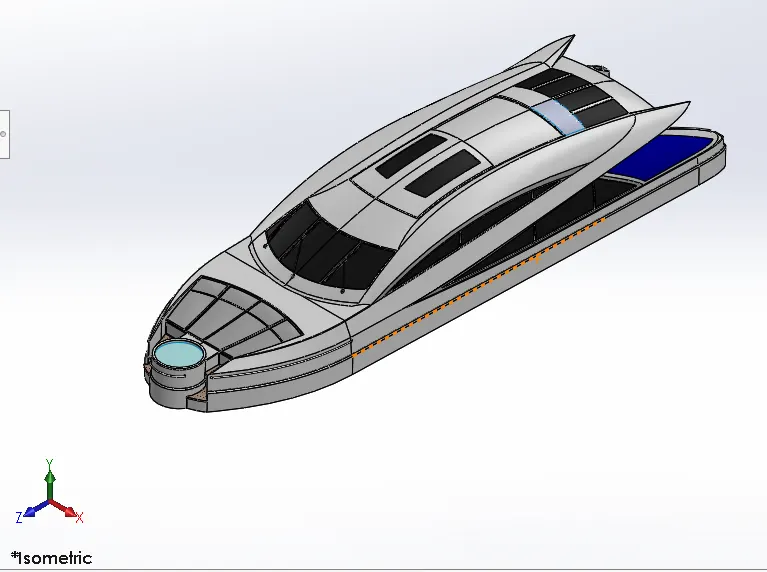
Fig.8 Isometric View of Superstructure
Stepwise Features Applied on Modeling of Superstructure:
- Sketch
- Extrude cut
- Project Curve
- Offset surface
- Surface fill
- Surface sweep
- Dome
- Surface trim
- Knit surface
- Extend surface
- Ruled surface
- Split line
- Delete face
- Mirror
- Fillet
- Chamfer
- Appearance
- Radar Mast - These mounts are constructed of high-quality marine grade aluminum and treated with an anodized primer then finished with brilliant white powder coated finish.
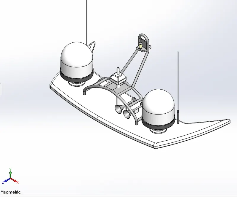
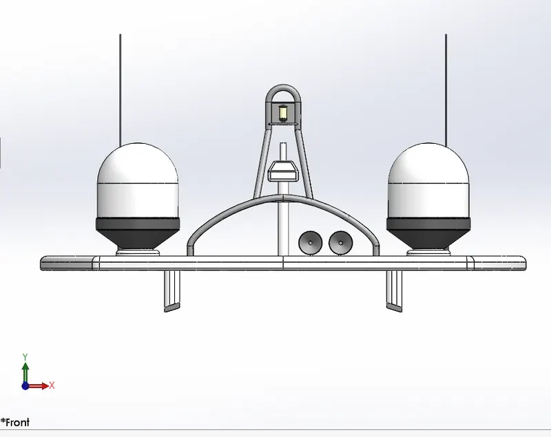
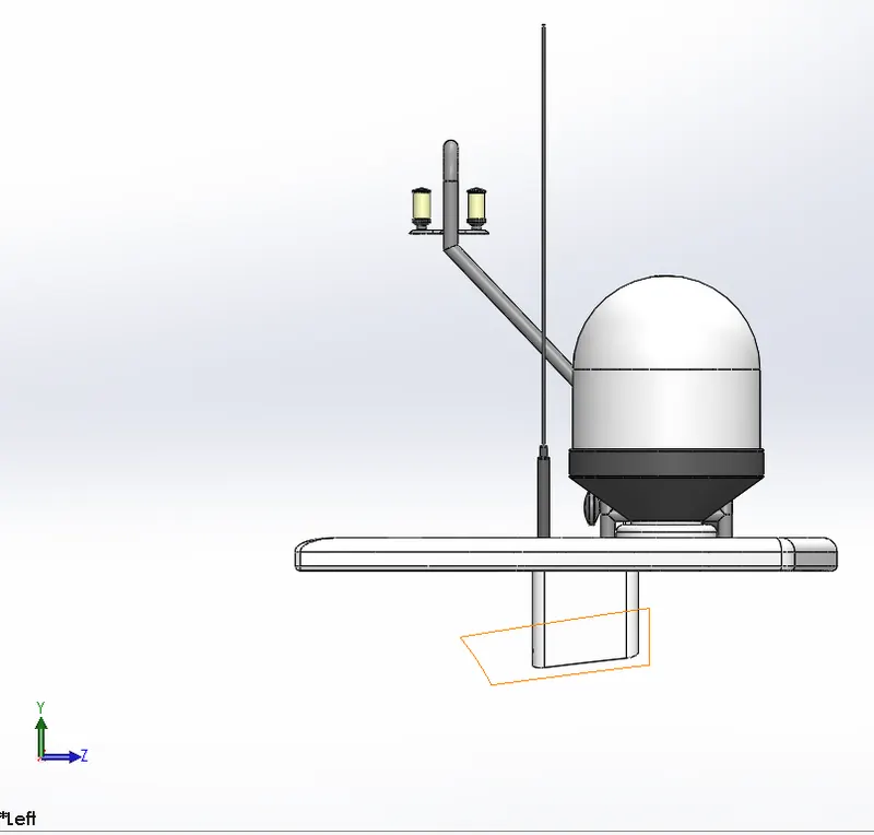
Fig.9 Isometric View of Radar mast
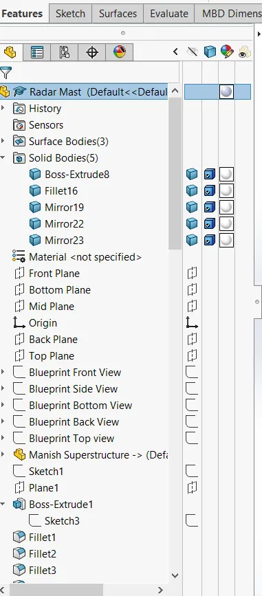
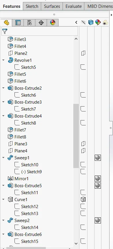
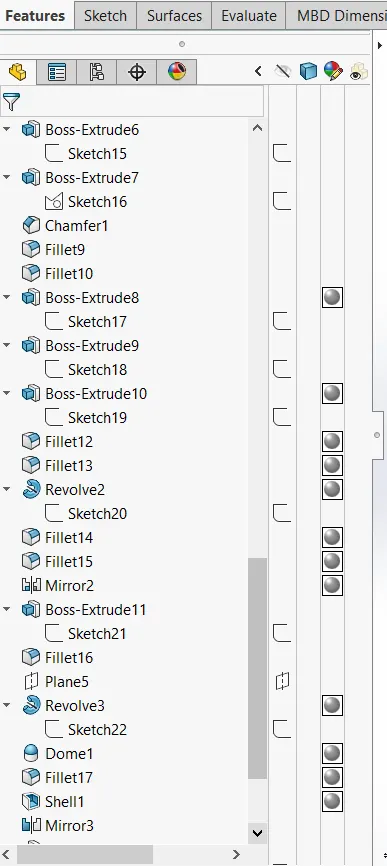
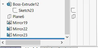
Stepwise Features Applied on Modeling of Radar Mast:
- Sketch
- Revolved Boss/Base
- Extrude Boss/Base
- Mirror
- Project Curve
- Chamfer
- Fillet
- Appearance
Assembly of Sunseeker Predator Yacht:
You can build complex assemblies consisting of many components, which can be parts or other assemblies, called subassemblies. For most operations, the behaviour of components is the same for both types. Adding a component to an assembly creates a link between the assembly and the component.
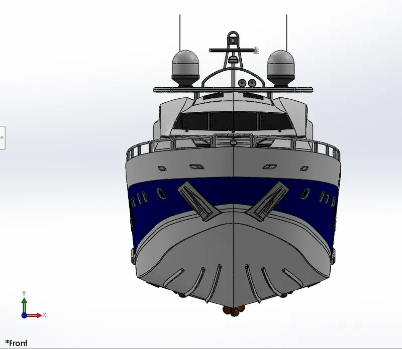
Fig.10 Front View of Yacht
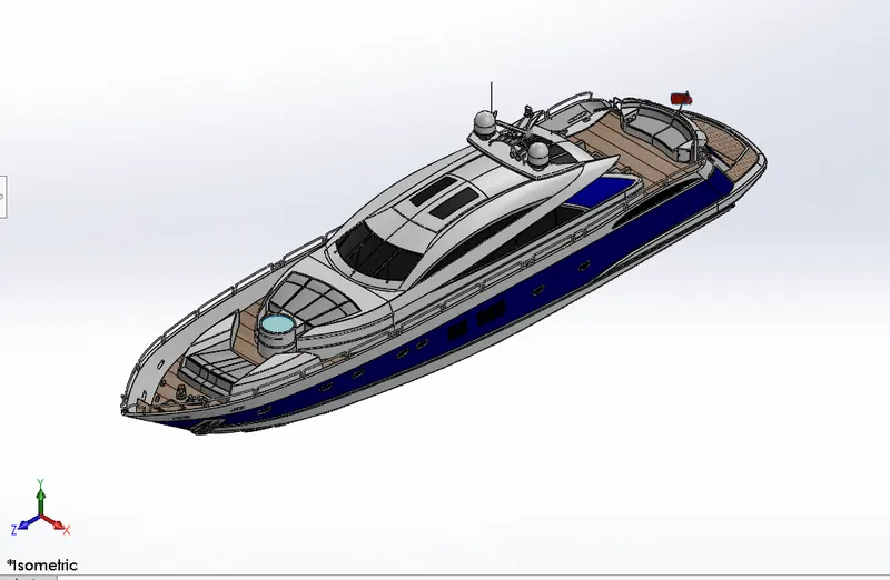
Fig.11 Isometric View of Yacht
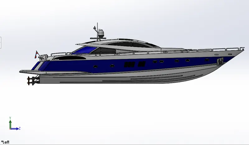
Fig.12 Left Side View
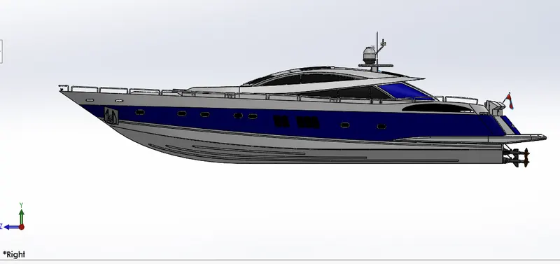
Fig.13 Right Side View
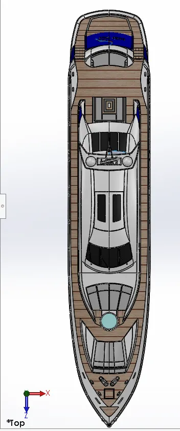
Fig.14 Top View
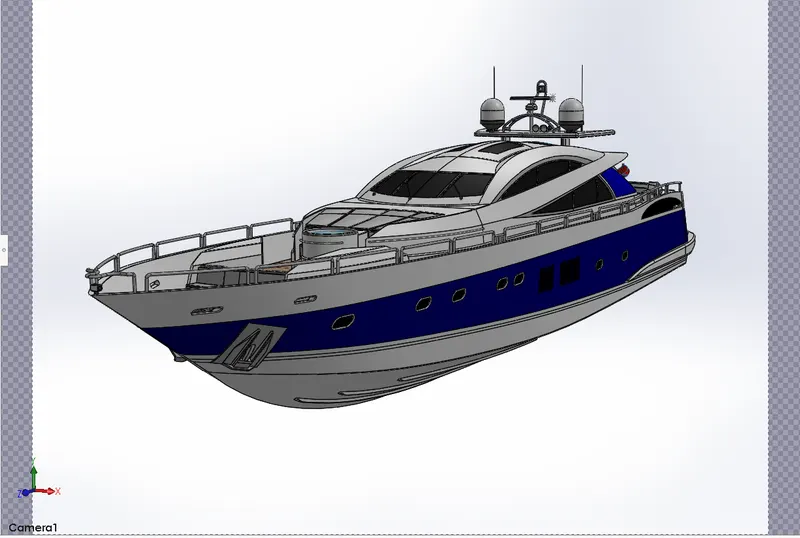
Fig.15 Camera View
Rendering of Sunseeker Predator Yacht
It is the photorealistic view of Predator Yacht by Using Photo view 360 and Solidworks Visualize.
- Load your Model
- Apply Appearances to your model through Paint
- Apply a Scene
- Apply Cameras
- Render it out
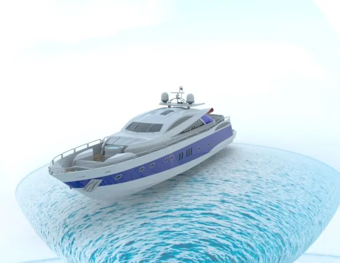
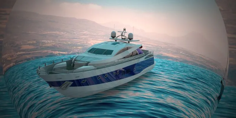
Fig. 16 Rendered View
Conclusion:
- All the Parts of Sunseeker Predator Yacht are Modeled by Using Solidworks
- All the solid parts are Assembled successfully using Solidworks
- Rendering of the assembly is done successfully using photo view 360 and Solidworks Visualize.