Roof challenge
ROOF DESIGN OF HATCHBACK CAR AND ANALYSIS (BIW)
OBJECTIVE
To design a ROOF of the car from the given styling surface with consideration of all engineering aspects which are draft analysis for DFM, heat distortion, and snow load prediction to justify roof curvature.
INTRODUCTION
An automobile roof or car top is the portion of an automobile that sits above the passenger compartment, protecting the vehicle occupants from sun, wind, rain, and other external elements. this is called the roof.
To give strength to the roof we attached bow roofs. bow roof is nothing but it is a supporting sheet metal part.
Likewise in the front edge of the roof, there will be a sheet metal part called front roof rail. the windshield will come and cope right above the front roof rail which on the roof ditch area.
The rear roof rail as the name suggests it place on the end of the roof. the master section should have the right geometry so that the back door will attach to the ditch area with the help of henge to open and close the back door.
In this design phase, I used 3 bow roofs with one reinforcement.
PROCESS STEPS / APPROACH
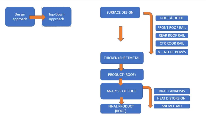
FIG.1 ( Process flow chart )
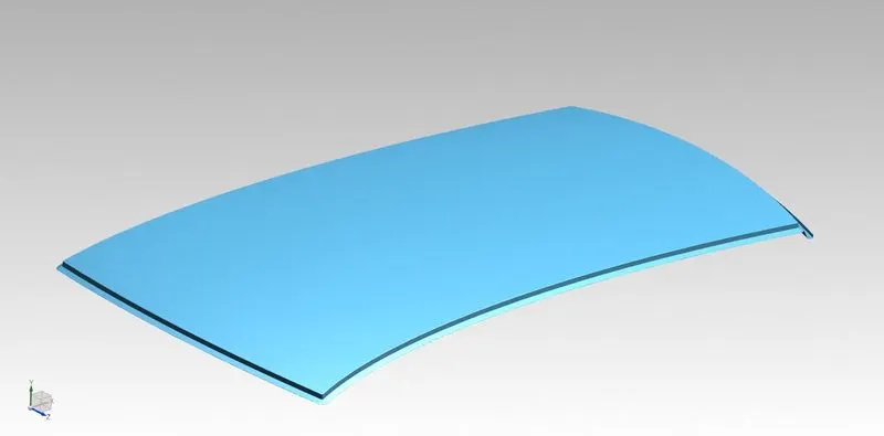
FIG.2 (Roof 1)
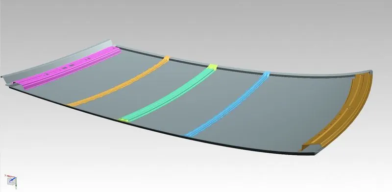
FIG.3 ( Roof 2)
Roof with details
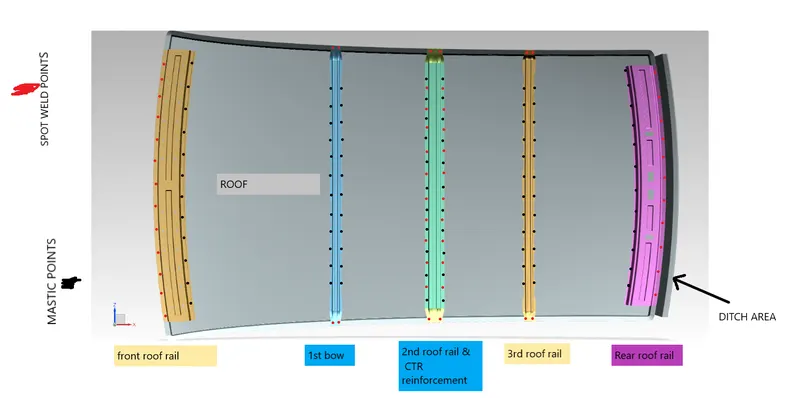
FIG.4 ( Roof with description)
FRONT ROOF RAIL
- The front roof rail is the one that joints the front roof side and the bodyside front.
- basically, the roof rails and the roofs are joined with the help of mastic and spot welding.
- the front most end is joined by spot weld and the backside will be joined by the mastics.
SPOT WELDING
- Spot welding (or resistance spot welding) is a type of electric resistance welding used to weld various sheet metal products, through a process in which contacting metal surface points are joined by the heat obtained from resistance to electric current.
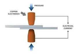
FIG.5 (SPOT WELDING)
MASTIC JOINT
Mastic in automotive sheet metal generally used to bond two different sheet metals by using additives and sealant. it is very helpful to reduce vibration between the sheet metal part.
given master section
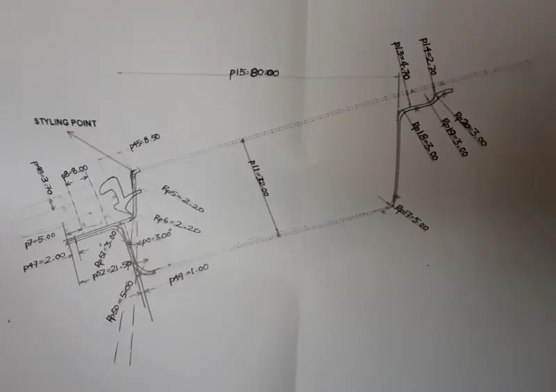
FIG.6 (Master section of FRR )
- the master sections are created considering the below criteria:
- Visibility, clearance between driver head and front roof rail backside edge.
- on the ditch area, there will be some extra components added to fix the windshield. components which made of absorbing shocks(or) vibration.
the master section of the front roof rail (without dimension info)
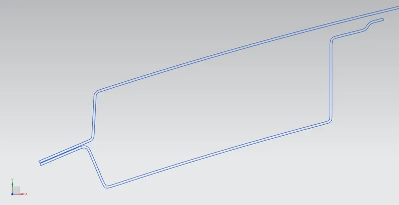
FIG. 7 ( Actual master Section of FRR )
bottom view
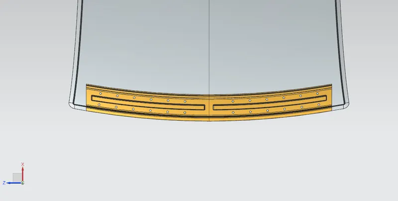
FIG. 8 (Bottom view of FRR )
cross-section (0Y) view
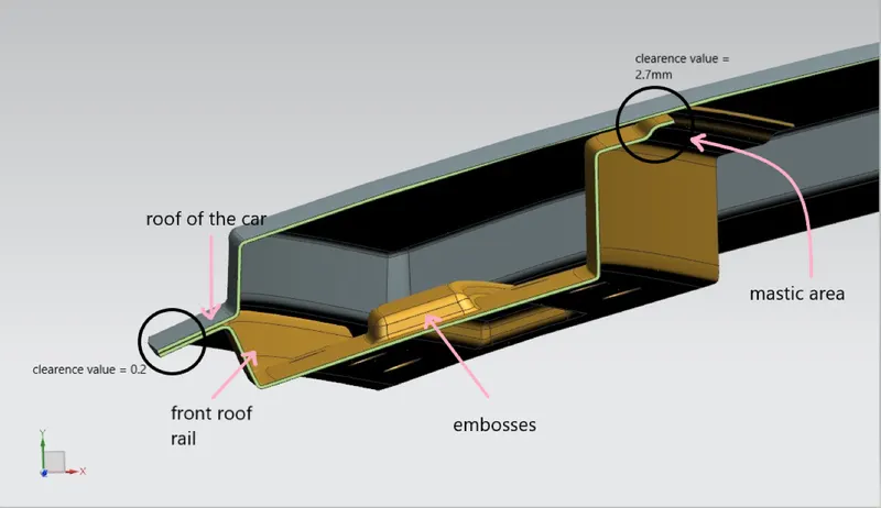
FIG. 9 (Cross-section of FRR )
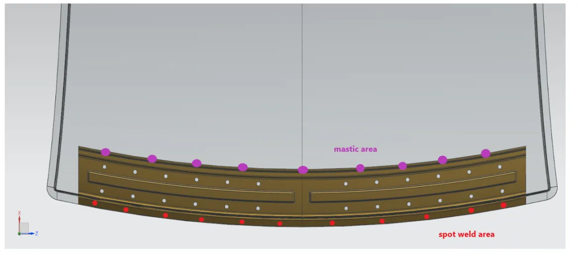
FIG. 10 (Top - View of FRR )
- the thickness of roof=0.75mm
- front rail roof thickness=0.75mm
- embosses are created to improve the strength of the FRR.
REAR ROOF RAIL
- REAR roof rail is attached at the end of the roof as shown in fig. back door will come and attach with the rear roof rail with the help of henge attachments.
- while designing the rear roof rail we have to consider the backside view clearance so the driver able to see backward through the windshield. which is called rear visibility criteria.
the master section of rear roof rail (without dimension info)
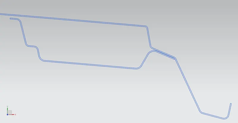
FIG. 11 ( Actual Master Section of RRR )
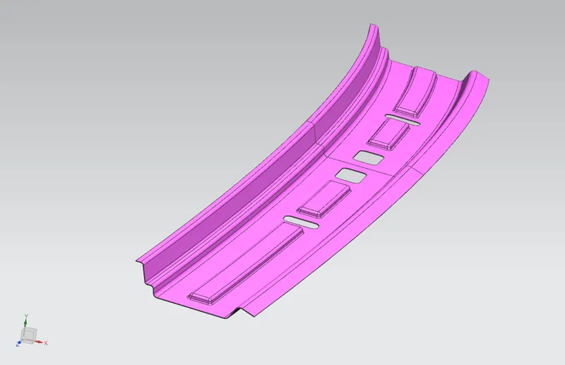
FIG. 12 (RRR)
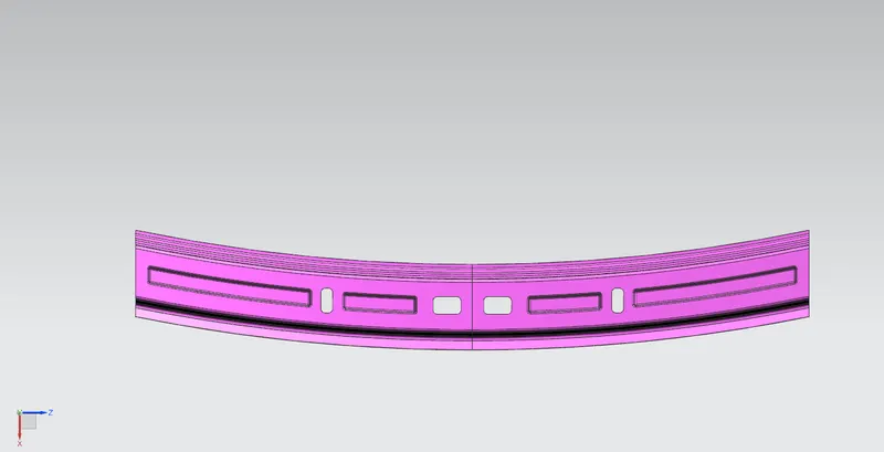
FIG. 13 ( Bottom of RRR)
mastic and spot weld joints are used as similar as the FRR . to joint RRR with the roof.
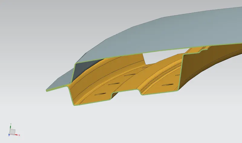
FIG. 14 ( Cross-section of RRR)
- the thickness of rear roof rail = 0.75
- the thickness of the roof 0.75
- embosses are created to improve the strength and holes were created to minimizing the material weight. lesser the weight higher the performance of the car.
ROOF BOW 1
these roof bows were created to improve the stiffness of the roof. since if the car was too long or too height also the no. of bow roof are also increased.
here I have created 3 bow roofs.
bow roof master section (without dimension)
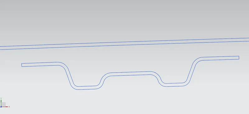
FIG. 15 ( Mater section of 1st bow's)
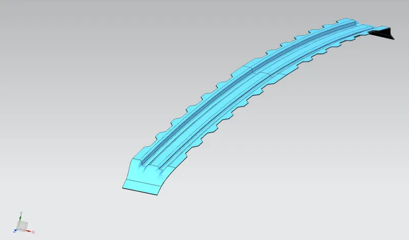
FIG. (1st bow roof )
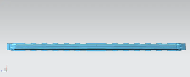
FIG. 16 (Top view of 1st bow's )
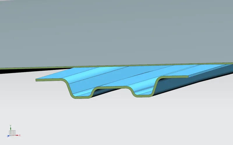
FIG. 17 ( Cross-section of bows)
- the thickness of bow roof 1 = 0.75mm=roof thickness
- gap between the roof and the bow was 3.3 for mastic bond.
- area for mastic was created.
- bend, flanges, embosses were created to strengthening the roof.
CENTER BOW ROOF AND REINFORCEMENT
it is located center that's why it is called the center bow. with reinforcement, the strength of the roof improved within the section.
center bow roof master section (without dimension)
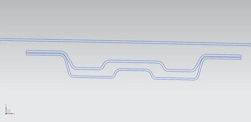
FIG. 18 ( Actual master section of CTR )
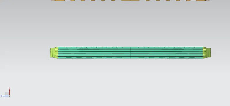
FIG. 19 ( Top view of CTR)
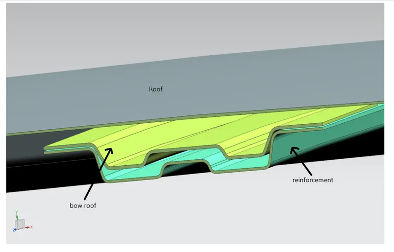
FIG. 20 (Cross-section of CTR )
- the thickness of roof, reinforcement, and bow roof=.75mm
- the gap between bow roof and roof is 3.3 mm for mastic implementation
- gap between bow roof and reinforcement is 0.2 it's a clearance value for spot welding.
- since we are added a reinforcement so the moment of inertia might be increased because the area is increased.
2nd BOW ROOF
bow roof master section (without dimension)
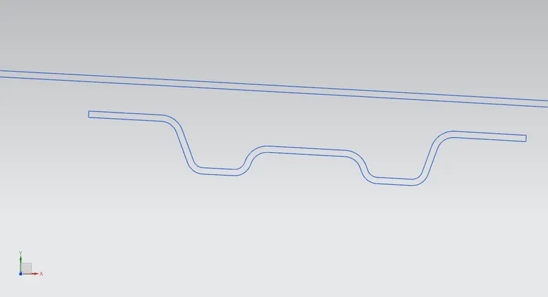
FIG. 21 ( Master-section of 2nd BOW )
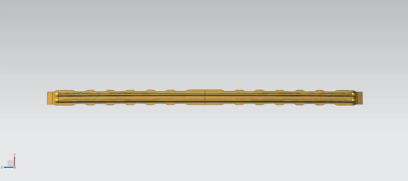
FIG. 22 ( Top view of 2nd BOW )
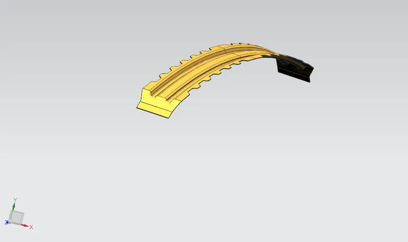
FIG. 23 ( 3D Image of 2nd BOW )
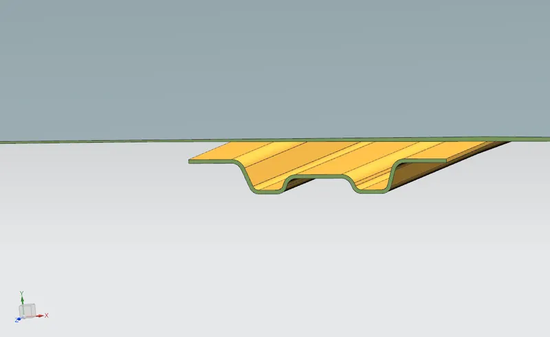
FIG. 24 ( Cross-section of 2nd BOW )
these are the detailed data of bow roofs and roofs.
DRAFT ANALYSIS
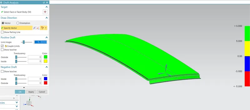
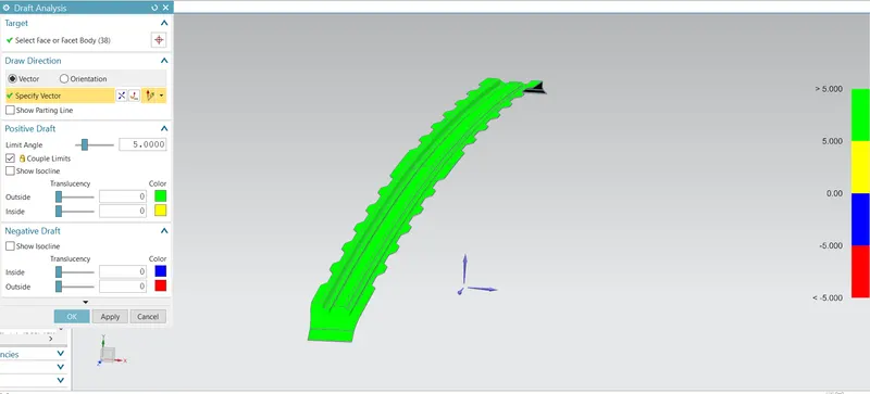
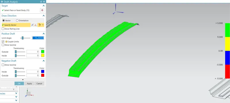
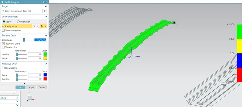
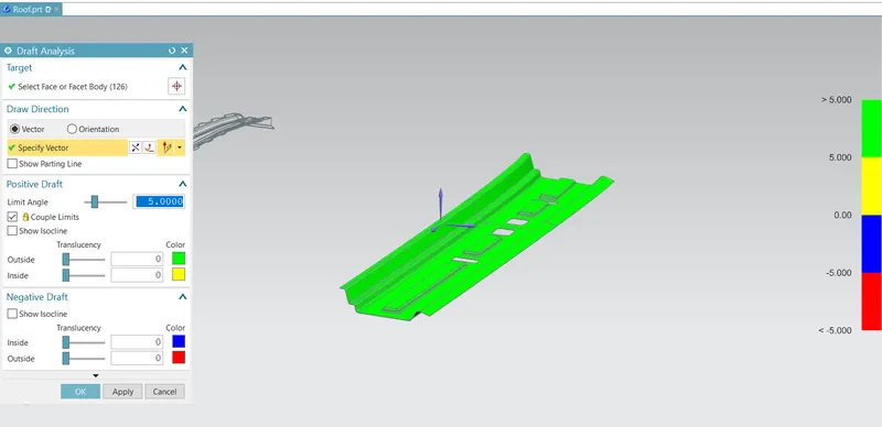
- Sheet metal parts are generated from a press tool or some forming tools, maybe the plastic parts which generally come out from the plastic molds and maybe the casting parts, all such kind of parts required some face on the surfaces which are parallel to the tooling direction.
- if we don't provide a draft on the surface then the tool will not come out and tool motion will destroy the surfaces or also reduced the finishing of surfaces.
- The draft is used for providing angles or tapers on product features such as walls, ribs, posts, and bosses that lie parallel to the direction of release from the mold eases part injection.
- Draught angles are designed in such a way that they will assist depart rejection. By doing so we have a reduced cycle time and improved productivity.
- Draft value for a particular part is mostly decided by the material used for making it.
- 3 degrees is a minimum for sheet metal when it's come to the draft angle.
TESTS WILL BE CONDUCTED
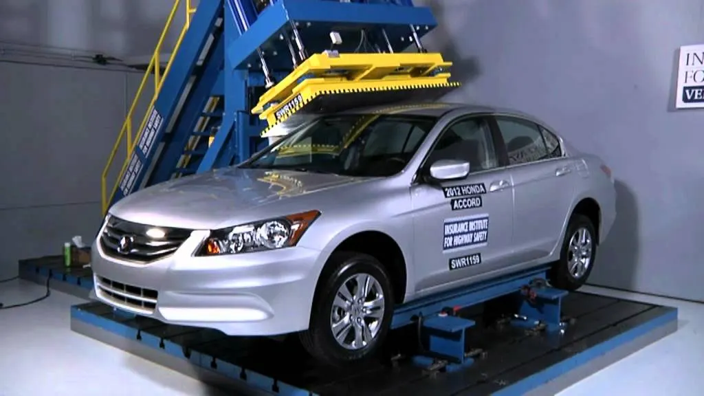
there is some physical test which will be conducted on the car roof which has been filled for passenger safety.
List of test
- Roof crash test
- Heat distortion test
- Snow load test
1. Rollcrash test
The roof over test is a very important test for the roof of the car.
This is the theoretical study to make sure the correct position of bow roofs. these are the prediction formulas.
Heat distortion criteria
Prediction formula
W =(1.73*10^(-3)*L)+(1.85*10^(-8)*(R^2/t))+(1.10*10^(-3)*I)-2.68
Judgement Condition : 2.7<W<3.5
where
l = roof length X- direction in mm ( 0Y section)
R = Roof curvature
R =(Rx*RY)/(Rx+Ry)
Rx = X curvature
Ry = y curvature
t = Roof plate thickmess in mm
I = bow roof span in mm
heat distortion table
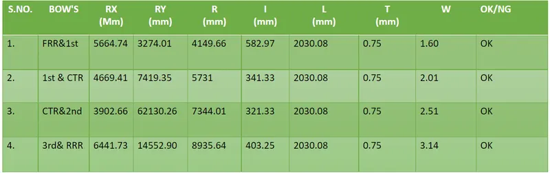
TABLE. 1 (Heat distortion test )
Hence the roof is passed in heat Distorsion test.
Snow load criteria
The purpose of calculating snow load criteria is during the winter session there will be snowfall. snow may settle on the roof of the car when the snow is removed the roof should back to its original position. this is the purpose of doing snow load prediction. the snow load prediction gives a 95% correct value compared to the actual test. so it is obviously a number.
Let's calculate the snow load criteria for our roof
Snow load prediction value
Qr = [Iy x t2] / [α x s x [(Rx + Ry)/2]2 x 10-8]
Where
α = My x Lx2 x 10-12 , My = Y(Ly-Y)
Judgement condition = Qr ≥ 3.1
250 ≤ s ≤ 380
t =Roof plate thickness in mm
Ly = Distance between the front roof rail and rear roof rails on the vehicle along with 0Y [mm]
Lx = Distance between left and right end of the roof on the roof bow in mm
width of the roof panel exposed on the surface
Y =Distance between front roof rail to roof bow in mm
s = distance for which roof bow bears divided load in mm
s =L1/2+L2/2
Iy Geometrical Moment of inertia of roof bow [y cross - section] in mm^4
Rx =Lateral direction curvature radius of roof panel Y cross-section on roof Bow in mm
Roof panel curvature radius of the length Lx in front view
Ry = Longitudinal direction curvature radius of the roof X cross-section on roof bow in mm
Roof panel X curvature radius of length inside view
Area moment of inertia values
Bow roof first
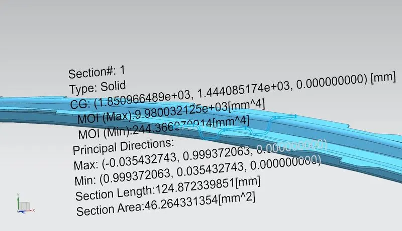
MOI =244.3660 mm4
CTR bow and reinforcement
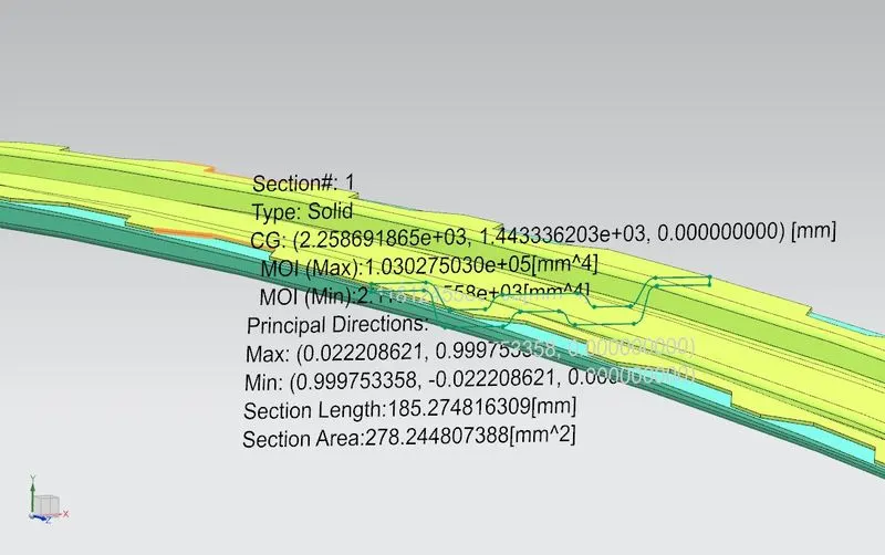
MOI = 2.1181e+3 mm4
Bow roof 3
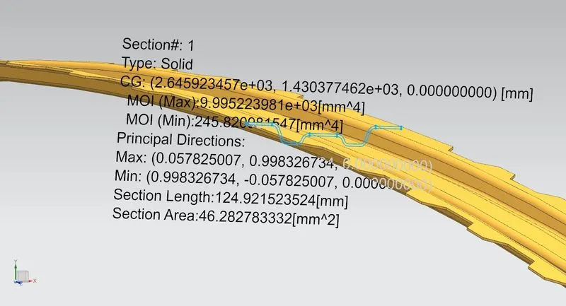
MOI = 245.8200 mm4
Snow load table

TABLE. 2 ( Snow load test results)
- As you know our Roof design does not get satisfying in the snow load prediction. because in some areas the vales were below 3.1
- there are some cases our roof may design may face this kind of problems. To neutralizing this problem we can do some action to get passes in the real-time Snow load test. those are given below.
Redesign the bow to improve the moment of inertia
- make changes in the position of bow's
- Add an extra bow make some bead or embossed on the roof to strengthening the roof from its displacement.
- passes the test report to the Styling team to change the radius of curvature of the part.
Action
I choose to add some beads and embosses on the roof. so the roof will get passed in the real-time snow load test. the embossed I created drastically improved the strength of the roof.
Final Roof design
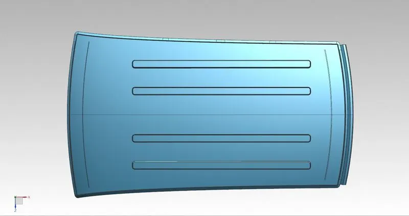
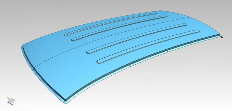
FIG. 36 ( Roof with pattern 3D view )
CONCLUSION
Finally, the roof of the hatchback car has been successfully designed with considering all the engineering aspects, and draft, heat distortion, and snow load analysis were done.