Advanced Sheet Metal Design Using NX Cad Challenge_2_Box Assembly
DESIGNING A BOX ASSEMBLY IN SHEET METAL
OBJECTIVE
- TO design a box assembly part in a sheet metal component by using siemens nx cad.
INTRODUCTION
- as we know sheetmetals are used in so many domains. we continiously using this because it has it's won advantages like lesser weight,reliable, it has a lesser manufacturing cost and very minimum level of maintanance.
- in this project i am going to design a box assembly in sheetmetal modeling. this assembly part will have a five individual parts. all together it is called a sheet metal assembly part.
METHODOLOGY USED
- the methodology that we are going to use for creating box which is probably a sheet metal part is top down method in the top down method the full assembly part will be created by a single template. which is a assembly template.
- the reason why i picked up top down method it because it is time saving method and very handy to edit a parts.
TOP DOWN METHOD
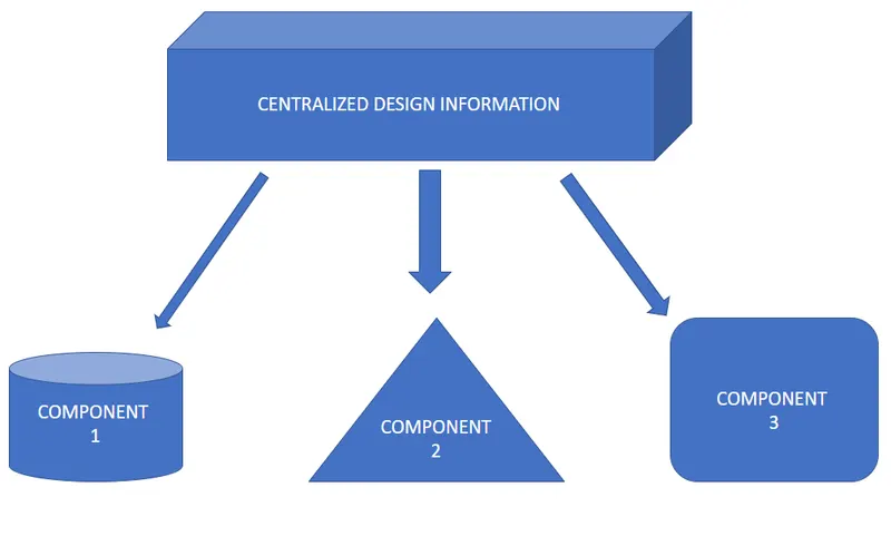
PROCESS FLOW DIAGRAM
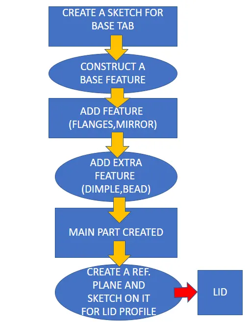
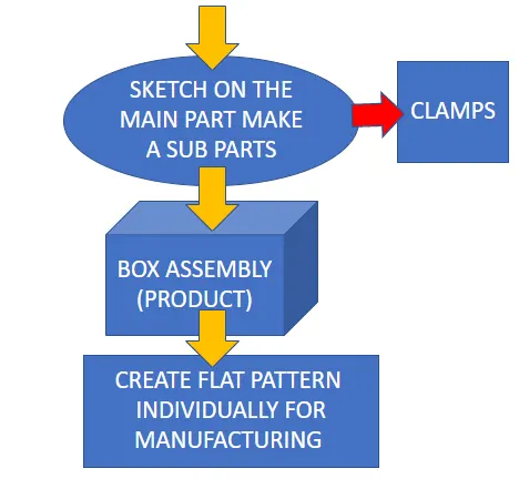
these are FRAME WORKS that i have used to create a box assembly. lets take a look into a detailed process
PRODUCT PROCESS STEPS AND PART DETAIL
BASE SKETCH(BOTTOM PART OF BOX)
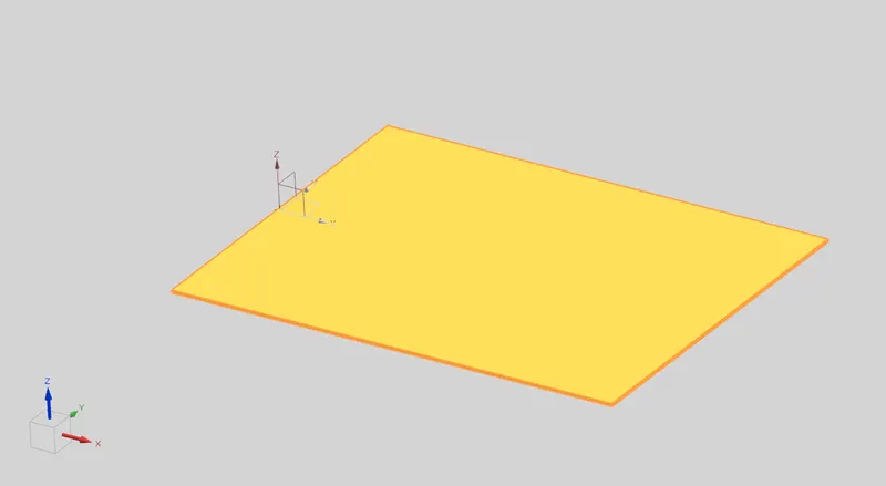
- Always a first step is create a sketch for a base tab. and here i have applied a uniform thickness of 3mm. what the pic reflecting is a half of the box.
FLANGES
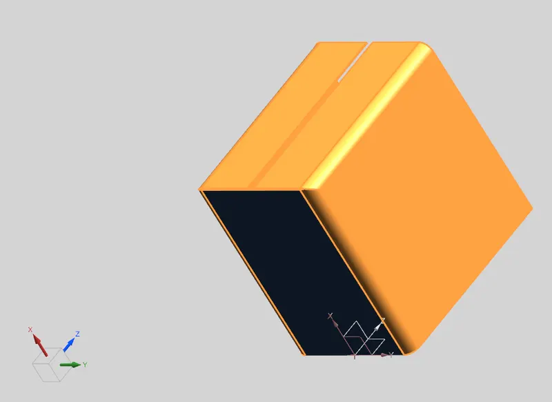
- create a flanges as in the picture to get an appropriate structure. and make sure you have added a closed corner to get a closed part.
HEM FLANGES
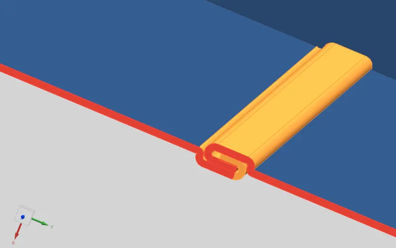
- create a flange and hem flange to enclosing the two short length flanges make sure that you have applied required clearance.
MIRROR BODY
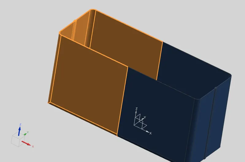
- use mirror body to mirroring the hole part respect with right side plane so then the result will be like this picture which is given below. now we have a good idea about our part.
and then use unite command to make a single body
DIMPLE AND BEAD
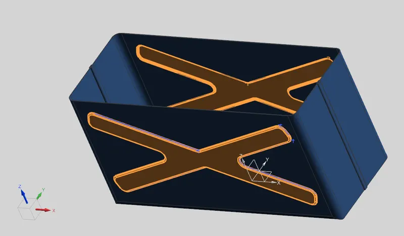
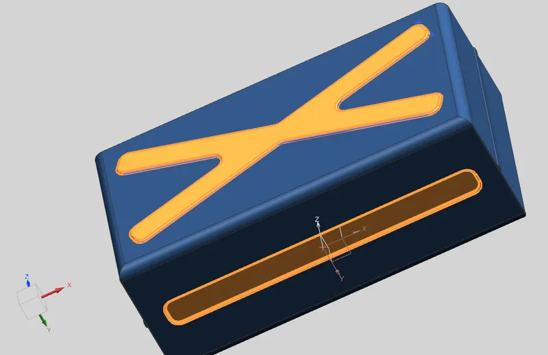
- the reason we use dimple is to improve the strenthness of the part. here i have added this structure profile for my dimple command. and i have used mirrror command to reflect on the opposite side too.
and i have followed the same steps for the bottom sides too.
UNBEND AND REBEND
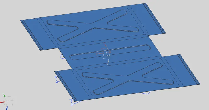
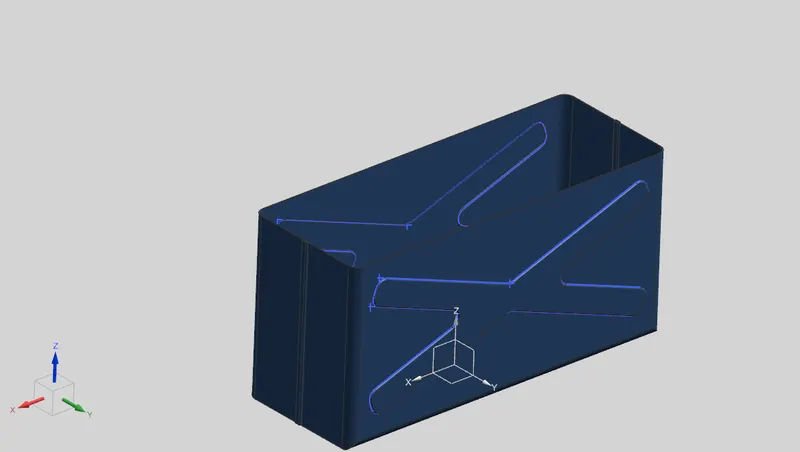
- as we know we are working on the sheet metal. it can be rebend to its flat position then only its a sheet metal.
HEM FLANGE
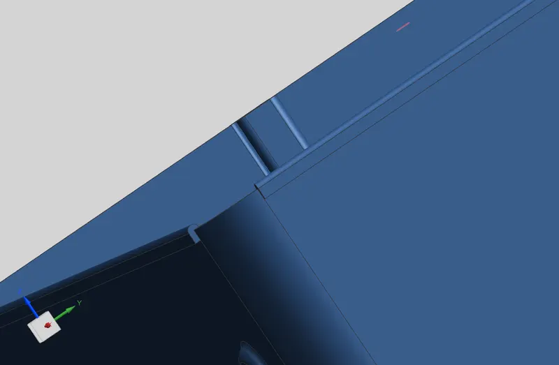
- thesse hem will helped to increase a strength of material in the corner portion.
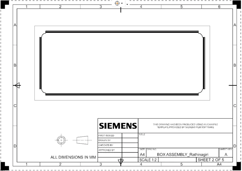
CREATE A LID
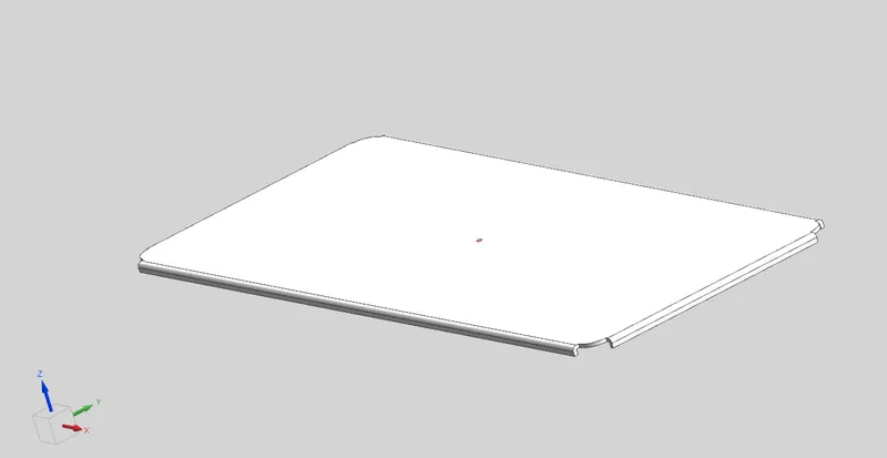
- a lid it will be a top portion of our assembly part for making a sketch we have to create new plane parallel to the top plane with required distance then add a tab to make a profile it has 2 mm thickness. and add flanges. make sure it accurately fitted with box.
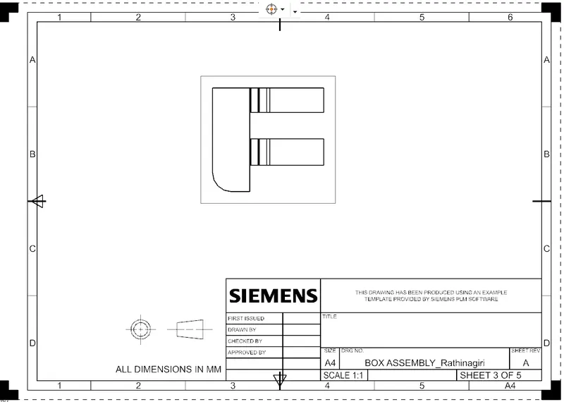
CLAMPS
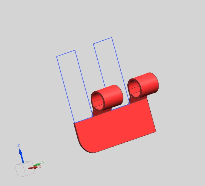
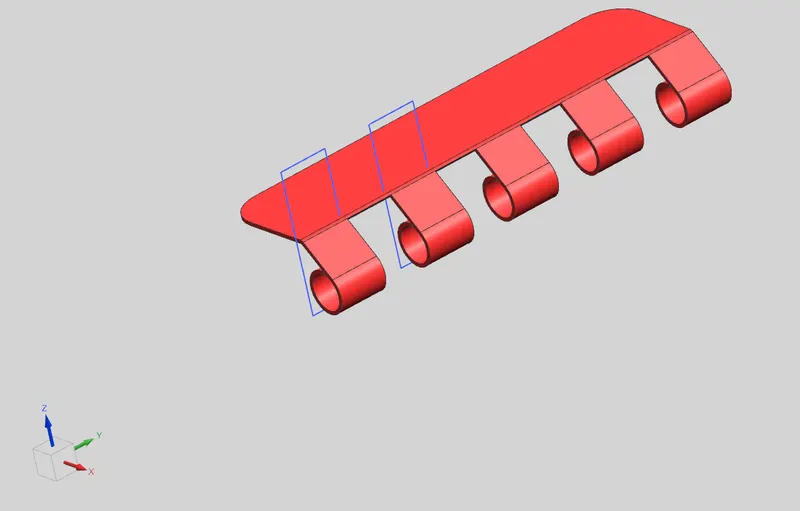
- firstly sketch on the box and make a tab to create a flat profile.
- make a flange 40 degree.
- again a vertical flange.
- add a cirular hem flange as shown in fig.
- unbend the sheet metal to create a cutout.
- sketch on the part and use the sketch as a profile for create normal cutout.
- finally rebend again.
the part will be like this
MIRROR
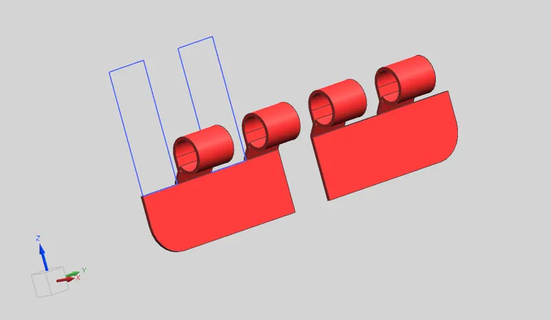
- mirror this part to opposite like this
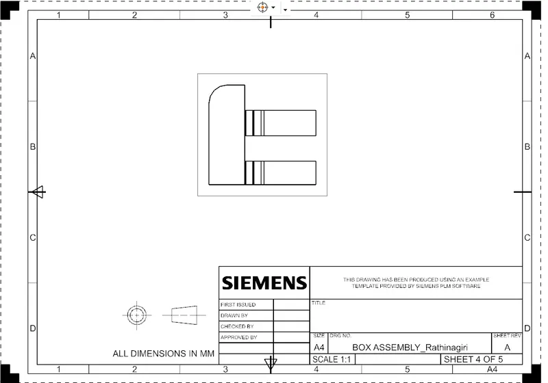
CLAMP 2
- sketch on the lid to make a pair clamp and add break corner to eliminate sharp edges.
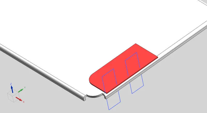
after applied some similar tools which we have applied recently then we will get a part like this add unite command to combine.
TOOLS USED
- tab
- flange
- unbend
- normal cutout
- rebend
- combine.
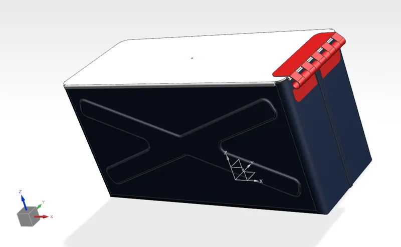
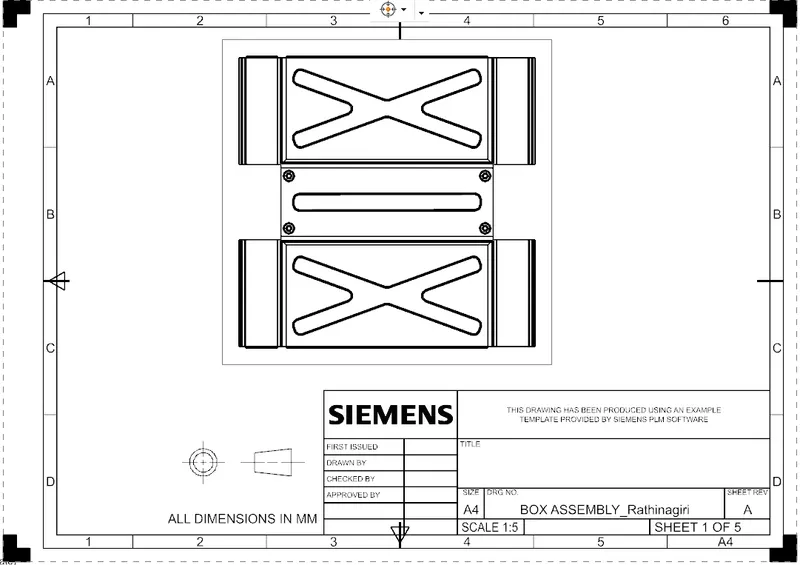
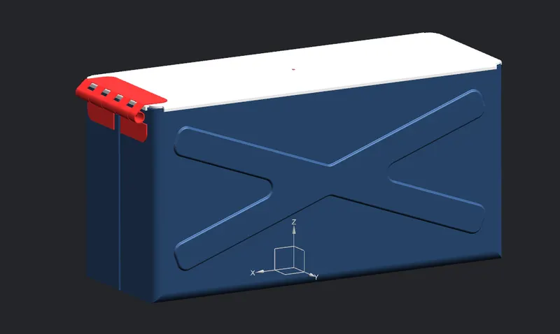
BOX ASSEBLY
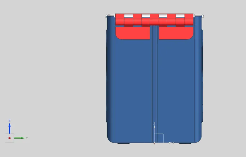
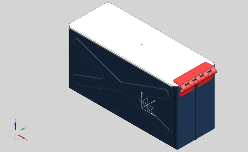
- all parts together here our box assembly created.
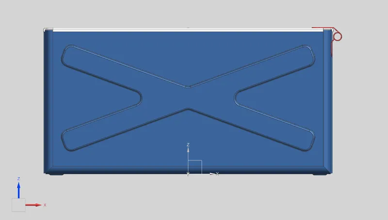
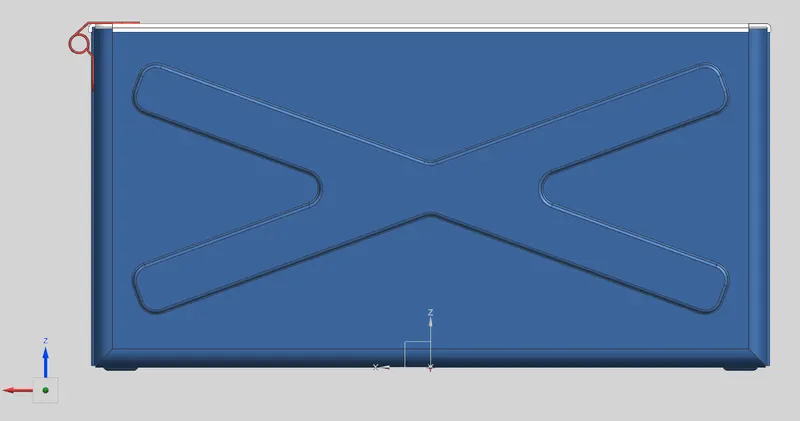
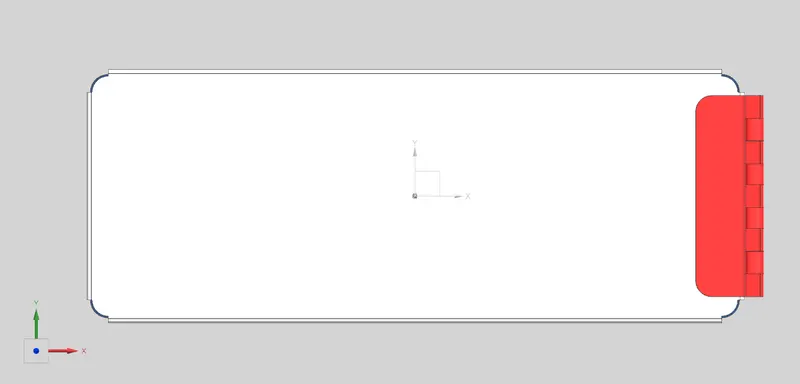
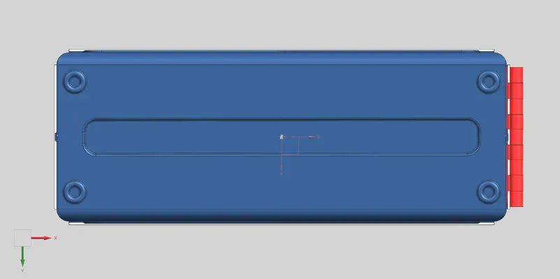
ORTHOGRAPIC VIEWS
- representing 3 dimentional part into 2 dimentional plane is called orthograpic view
FRONTVIEW
BACK VIEW
RIGHT SIDE VIEW
TOP VIEW
BOTTOM VIEW
ISOMETRIC VIEW
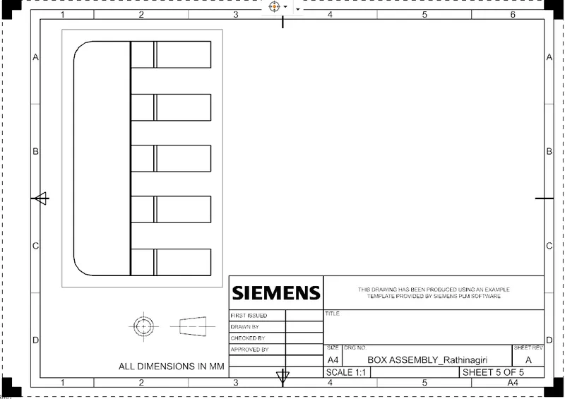
DRAFTING VIEWS
BOX
LID
CLAMPS
CONCLUSION
- here i have sucessfully designed a sheet metal box assembly by using nx cad through this journey i have learned several tools and concepts.