Photo Realistic Rendering of an american chopper and complete design
OBJECTIVE
To design an American chopper model with appropriate geometric data by using a bottom-up approach and create rendering images.
INTRIDUCTION
- The world that we are living in is not the same as compared to 50 years back. We cannot deny this fact at all right.
It happens, and it will happen regardless of time zone. It is possible because of science and engineering.
- As we know before manufacturing any of a product the first step is to design a product. By designing a product instead of doing traditional method we can save a huge amount of resources such as money, materials, human, power and a lot.
- Here we are designing American chopper which one of my all-time favorite bikes.
DESIGN METHODOLOGY
DESIGN PROCESS
- The design process will help us to design the products considering the impacts on other stages.
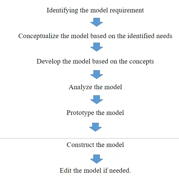
- This is how a brand new product is designed.
DESIGN APPROACH
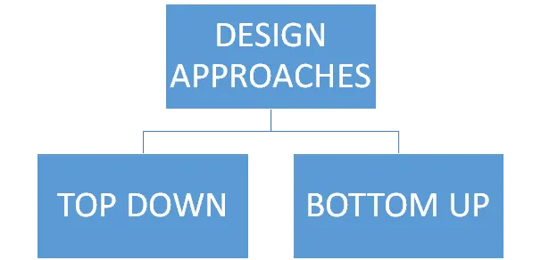
- Design approach which means how we are going to design a product a pre-step for designing a product.
- There are two different types are out there when we came into solid works top-down methodology and bottom-up methodology.
Each one has its own significance.
TOP-DOWN
- The top-down method is a convenient one over compared to the bottom-up method.
Because the hole design of a product will be designed by the assembly template itself.
BOTTOM-UP
- In the bottom-up method, each part are designed separately once all of the parts are done with designing then all the parts are performed in the assembly section there we can assemble different parts of the product, in this case, a chopper.
- Different types of mates are used to assemble parts.
These are the two different methods.
APPROACHES USED
- To designing an American chopper we have used a bottom-up method the reason we are picked this to understand better each one of the parts.
FLOW DIAGRAM OF DESIGN PROCESS
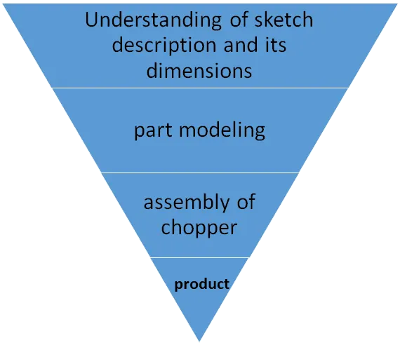
These are the steps and this is how the product was designed.
TOOLS
- Tools are more helpful to create, edit a sketch or a part of the product. There are a lot of tools are out there in any software.
- As I said earlier we are using solid works 2019 which has a lot of tools to create a sketch or apart.
Solid work is one of the user-friendly software.
Given below I have described the tools that I used to design an American chopper.
1.line
2.arc
3.circle
4.rectangle
5.spline curve
6.fillet
7.chamfer
8,smart dimensions
9.trim entities
10.mirror entities ,Patterns
1.LINE
- A line is a one-dimensional figure which has length but not width. In geometry, there are different types of lines such as horizontal, vertical, parallel and etc.
Here we have used a construction line for a reference point.
- ARC
- An arc is any smooth curve joining any two points. Arc is any portion of the circumference of a circle.
- CIRCLE
- The circle is a round-shaped figure and it has no edges which are measured by its radius. And it’s a basic 2dimensional shape.
- RECTANGLE
- A rectangle is a four-sided polygon having all the internal edges of 90 degrees the opposite sides of the rectangle having the same lengths and are parallel.
- SPLINE CURVE
- These are used in computer designing for representing a smooth curve, it has an N number of points as per our requirement which is used to control a curve.
- FILLET
- Fillet is a rounding of the interior or exterior corner of a part design. Which is used to eliminate sharp edges in the part.
- CHAMFER
- It is a transitional edge between the two faces of an object.
- SMART DIMENSION
- It is a very handy tool to define a sketch by giving a required dimension.
- TRIM ENTITIES
- The trim tool is used to cut off a line between the two points.
- MIRROR
- The mirror tool in sketch used to mirror a sketch about a reference line is very beneficial to perform speedily. This tool is also used appeared in part (3d) modeling.
- PATTERNS
- Patterns are used to create an N number of sketch blocks (instances) by making reference to the original sketch.
TYPES PATTERNS
Linear pattern, circular pattern and etc.
Possibly these are tools that I have used to create a sketch of an American chopper.
FEATURES
- Features are used to create or edit a block that has plenty of credits. Here we are concentrating on some of the features that I used in solid work 2019 to create an American copper.
- Extrude
- Revolved
- Projected curve
- Sweep
- Split
- Combine
- Dome
- EXTRUDE
- Extrude is used to create a feature base/ boss by protruding a section in the normal direction, and all extrudes are begin with a section sketch.
We can do an extrude base/boss as well as we can perform an extrude cut
- REVOLVED
- Revolves add or remove materials by revolving one are more profile around centerline we can create revolved bases/boss, revolved cut and revolved surfaces. Revolved can be done on solid, thin, and surface areas.
- PROJECTED CURVE
- The projected curve is used to create a path for sweep or lofts this curve is drawn on any of two-quadrant for making this curve we have to use two different plane sketches which have some condition between the two sketches.
- SWEEP
- The sweep feature helps us to create a closed (or) open profile 3D part by using a 2d profile and path.
- SPLIT
- the Split feature to create multiple parts from an existing part. You can create separate part files, and form an assembly from the new parts. You can split one or more solid or surface bodies.
- COMBINE
- The combine is used to combine different bodies into one solid body.
- DOME
- The Dome feature will help to create a domed part on the selected face.
RELATIONS B/T SKETCH ENTITIES
- Sketch entities relations are the most important one when it comes to sketching a part by effective uses of these we can easily define our sketches. Some of the most common relations are given below
- Horizontal,vertical,tangent,concentric,coincident,equal,parallel,collinear,mid point relation, merge point and etc.
These relations are very helpful we mating our parts in assembly sections.
DESIGNING A PART OF AMERICAN CHOPPER
- As I said earlier we choose a bottom-up method to create our chopper so what we are going to do is to design a every single part individually and put it together in an assembly section.
Given below the parts of our American chopper
- Kickstand
- Front fender
- Rear fender
- Oil tank
- Chain
- Pedal
- Front-wheel
- Rear-wheel
- Fork
- Chassis
- Engine
Gas tank
- KICK STAND
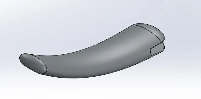
Tools and features used
- Ellipse
- Spline
- Loft
- Dome
- Rectangles
- Split
- Fillet
- FRONT FENDER
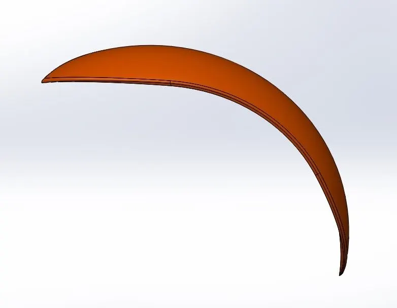
Tools and features used
- Line
- Arc
- Revolved
- Spline
- Split
- Fillet
- Offset
- REAR FENDER
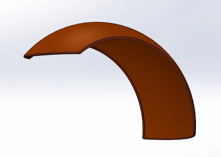
Tools and features used
- Line
- Arc
- Spline
- Split cut
- Fillet
- offset
- OIL TANK
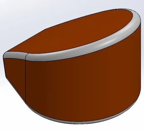
Tools and features used
- Line
- Arc
- Mirror
- Extrude
- Shell
- Combine
TRANSMISSION BELT
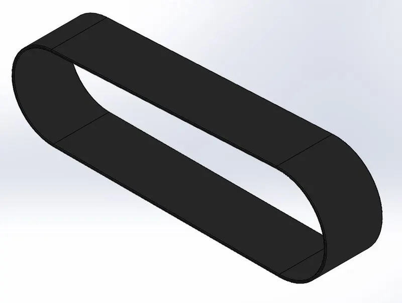
Tools and features used
- Line
- Arc, circle, trim
- Extrude
- CHAIN
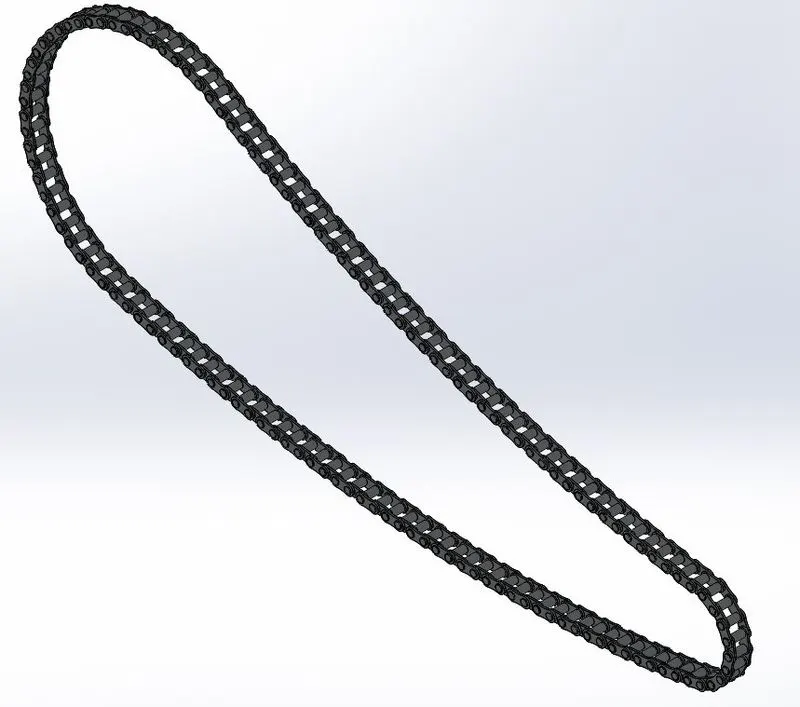
Tools and features used
- Circle
- Arc
- Block
- Slot
- Curve driven pattern
- Extrude
- Fillet
- Convert entity
- offset
- Mirror
6.PEDAL
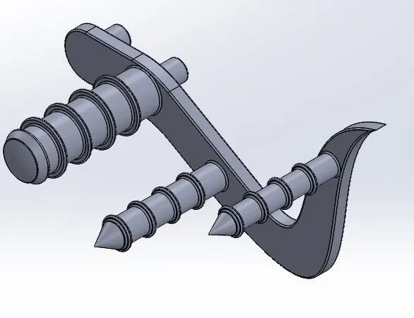
Tools and features used
- Line
- Arc
- Circle
- Spline
- Extrude
- Fillet
- Revolve
- Dome
- Chamfer
- Linear pattern
- offset
7.FRONT WHEEL
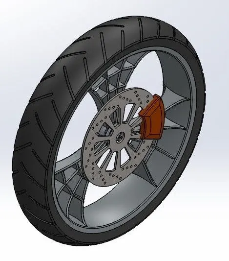
Tools and features used
- Line
- Arc
- Revolve
- Spline
- Extrude
- Convert entities
- Mirror
- Extrude cut
- Circular pattern, linear pattern
- Fillet
- Circle
- Rectangle
8.REAR WHEEL
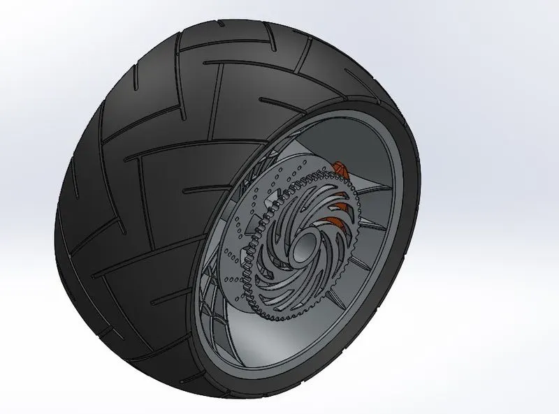
Tools and features used
- Line
- Arc
- Revolve
- Spline
- Extrude
- Convert entities
- Mirror
- Extrude cut
- Circular pattern, linear pattern
- Fillet
- Circle
- Rectangle
9.FORK
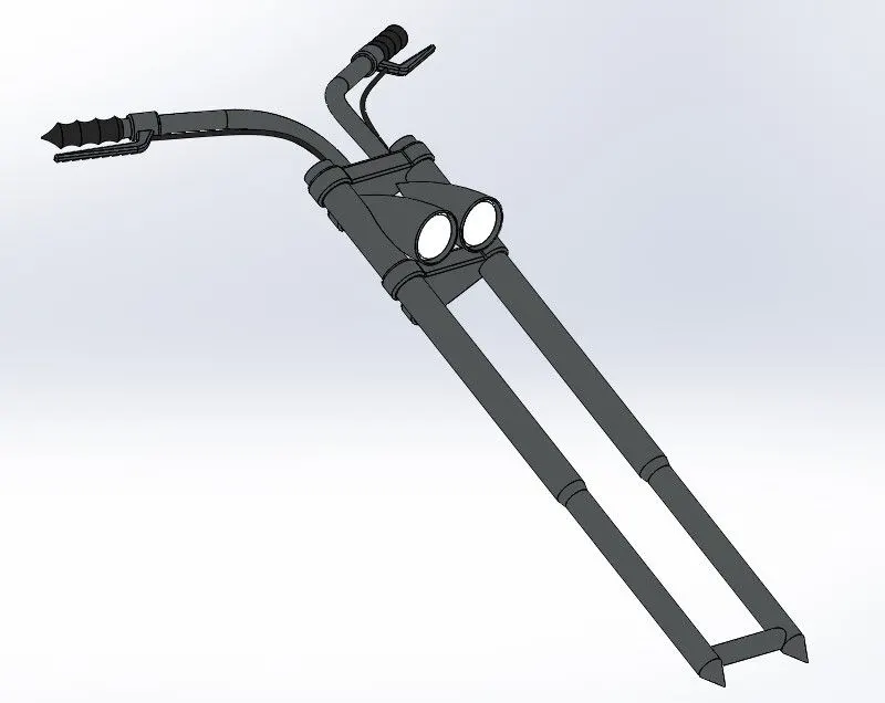
Tools and features used
- Line
- Revolve
- Extrude
- Fillet
- Linear pattern
- Move
- Dome
- Convert entities
- Sweep base
- Projected curve
- Mirror, sweep, offset
10.CHASSIS
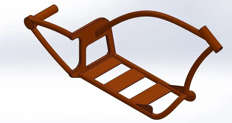
Tools and features used
- Sketch picture
- Line
- Spline
- Curve
- Circle
- Extrude cut
- Sweep base
- Extrude
- Dome
- Swept base
- Split
- Sweep base
- Fillet
- ENGINE
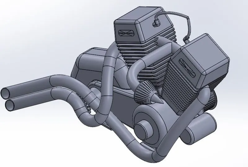
Tools and features used
Sketch picture
- Line
- Arc
- Circle
- Spline
- Projected curve
- Fillet
- Mirror
- Linear pattern
- Circular pattern
- Extrude cut
- Extrude base
- Chamfer, split,offset
- GAS TANK
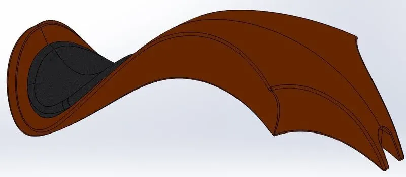
Tools and features used
- Line
- Spline
- Curve
- Swept surface
- Trim
- Trim surface
- Projected curve
- Surface loft
- Convert entities
- Mirror
- Split
- Fillet
- Shell
- Offset
ASSEMBLY OF AMERICAN CHOPPER
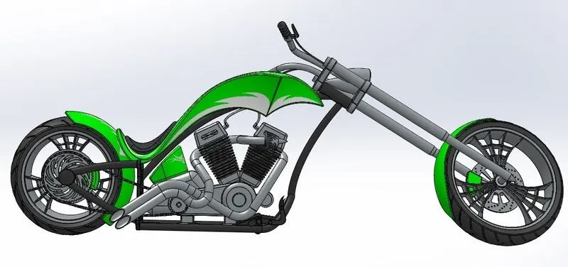
- In the assembly section, we are going to assemble all parts together to design a complete American chopper.
Their same tools called mates which are helped to assemble all parts together.
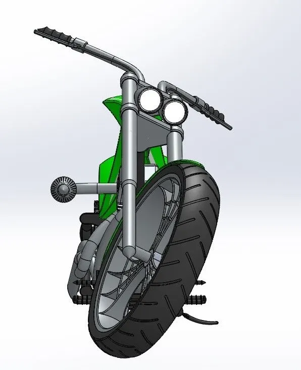
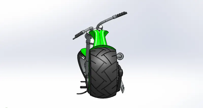
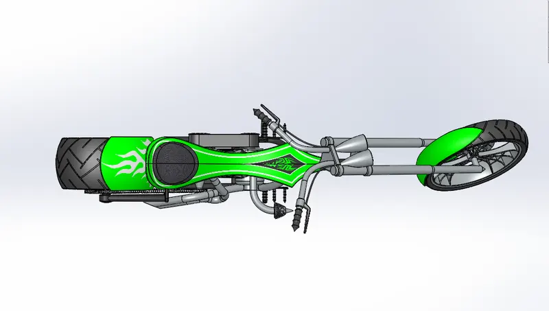
The complete design is given below
FRONT VIEW
RIGHT SIDE VIEW
LEFT SIDE VIEW
TOP VIEW
FRONT OF CHOPPER
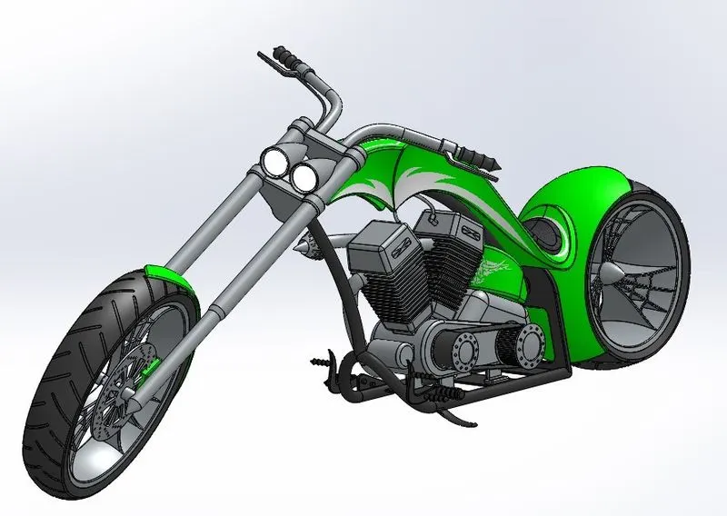
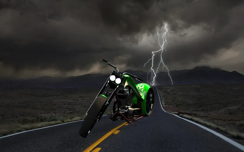
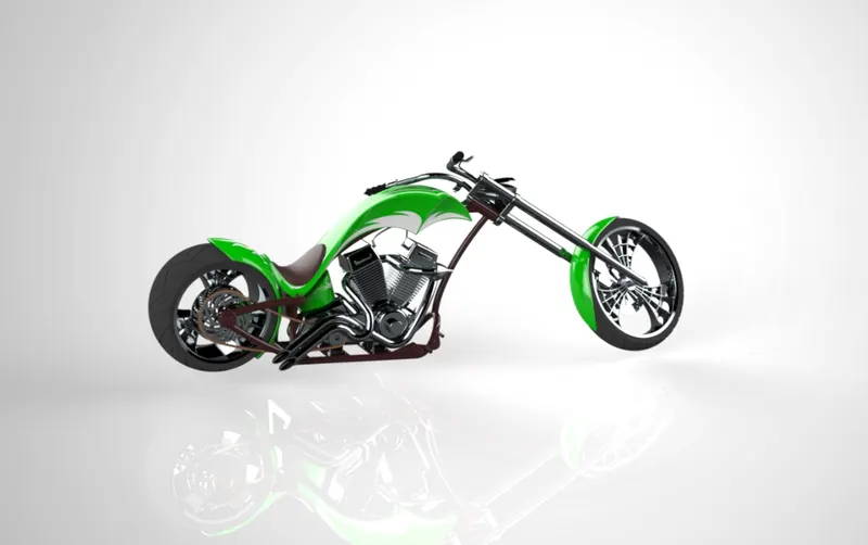
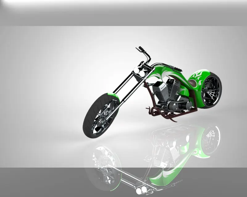
RENDERED IMAGES OF AMERICAN CHOPPER


CONCLUSION
Finally, we have designed an American chopper with constrained dimensions and the rendering process also has been done.