Roof challenge
Design of a Car Roof
Aim:
To design the car roof and the roof rails for strengthening the structure from the given styling surface and to do a curvature study to resist the heat distortion and snow load condition for the roof designed.
Abstract:
A car roof is not only meant for protecting the passengers inside the car from the outer weather conditions but also should be strong enough for resisting loads or impacts in case of an accident. To strengthen the roof of a car supports like roof rails and bows are added to the roof panel. These supports are usually thicker when compared to the sheet metal of the roof and are places with certain distances from each.
In this project, the heat distortion and the snow load conditions are considered for designing and strengthening the roof of the car. The roof rails and the bows are to be constructed as per the dimensions in the given master sketch.
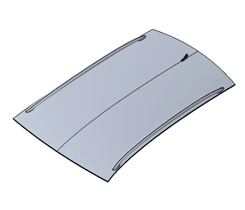
Fig 1: Given styling surface.
Procedure:
1. From the given styling surface, extract the roof surface in a new geometrical set so that for reference of the roof structure to create the roof rails and bows.
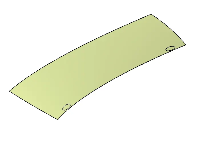
Fig 2: Extracted surface.
2. Create flanges on the edges of the roof panel for the provision of assembling the roof to the remaining components by welding process. The rear side of the roof flange should be constructed as shown below for the provision of the hinge assemble for the back door.
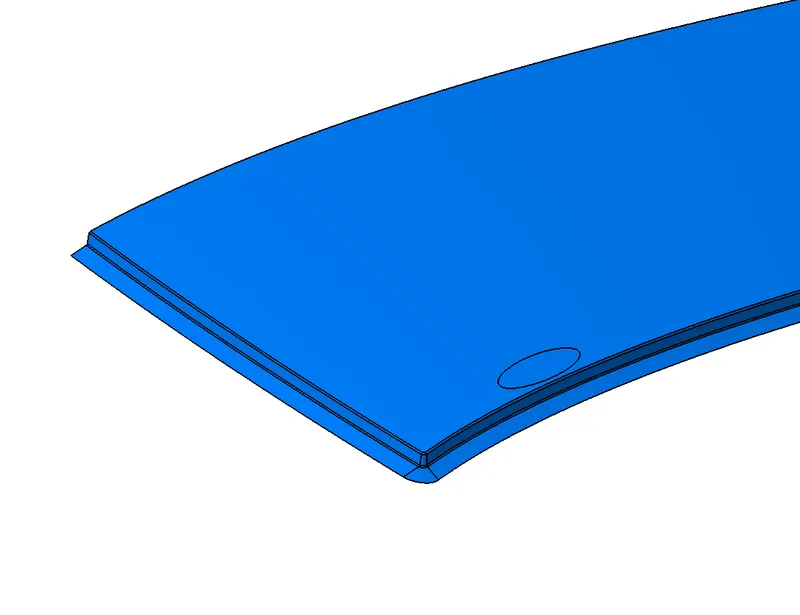
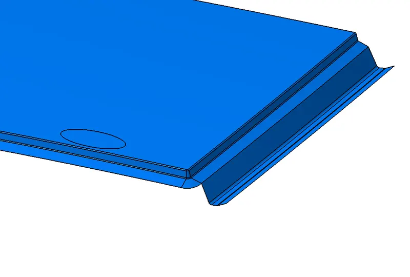
Fig 3: Flange provision for the roof Fig 4: Flange provision on the rear side of the roof.
3. Now, as per the master sketches given, construct the front and rear roof rails following the dimensions and maintaining the clearance between the roof and the roof rail. The steps for the construction of the roof rails are as shown below.
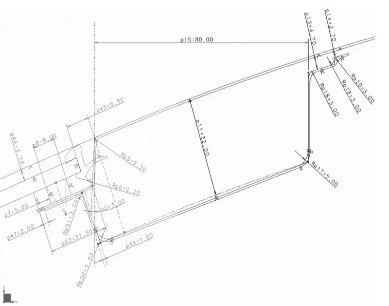
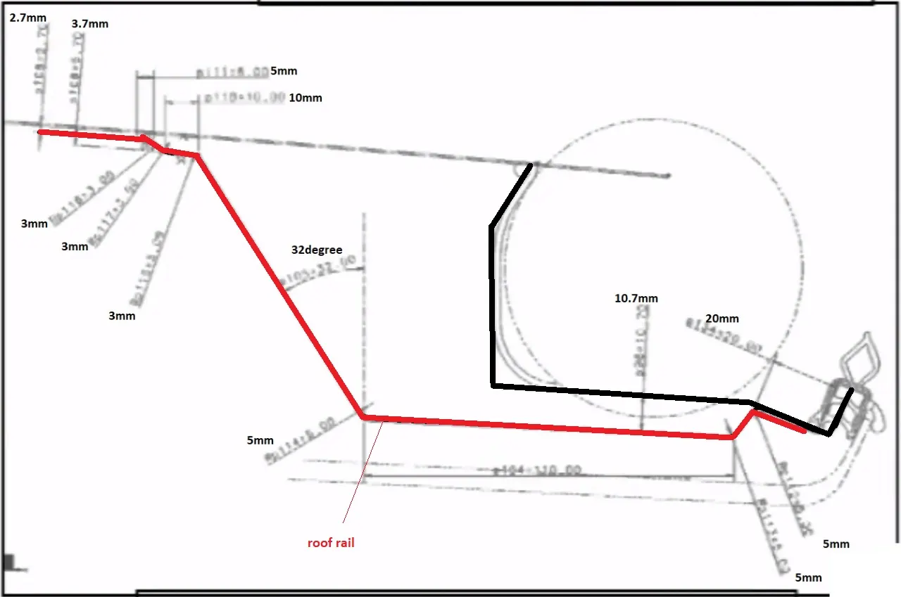
Fig 5: Front roof rail master sketch Fig 6: Rear roof rail master sketch.
a. From the extracted roof surface, offset the horizontal surfaces of the roof rail with the offset values as given in the master sketch.
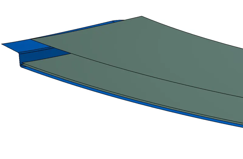
Fig 7: Offset surfaces as per master sketch values.
b. Split the offset surface below as per the mentioned width in the master sketch using the parallelism option.
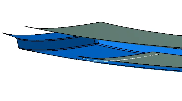
Fig 8: Split surface.
c. Now using the sweep surface option create a surface on the edge of the split surface with an angle as mentioned in the master sketch. The angle for creating flanges on a sheet metal should be more than 7 degrees and the sweep surface should be intersecting with the next offset surface as shown below.
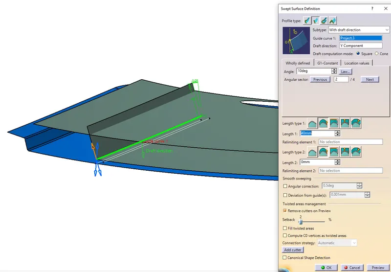
Fig 9: Sweep surfacing.
d. Now the intersecting surfaces should be trimmed as per the master sketch.
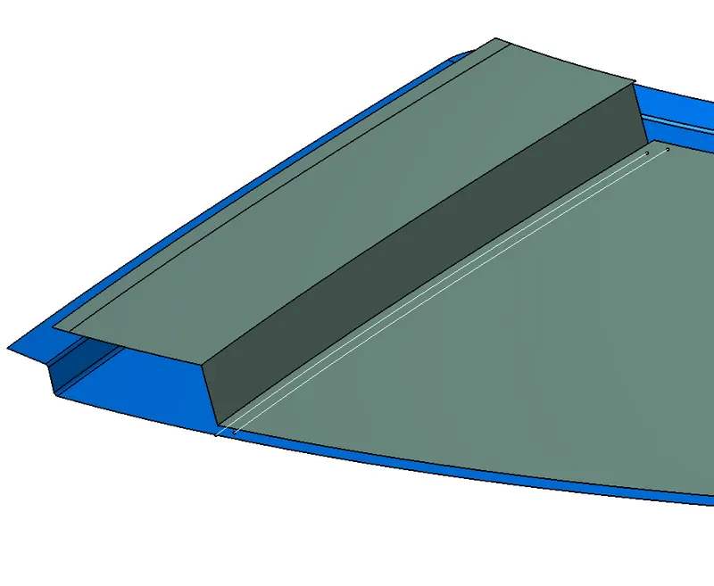
Fig 10: Trimmed surfaces.
e. Similarly, construct the remaining roof rail flanges and provide fillets on the sharp edges.
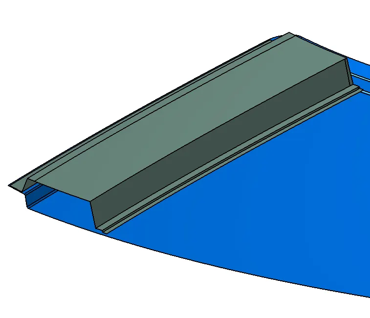
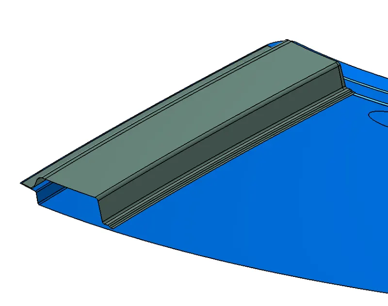
Fig 11: Constructed roof rail Fig 12: Fillet roof rail
f. Create embossments on the roof rail for strengthening the rails and for the provision of the reinforcements.
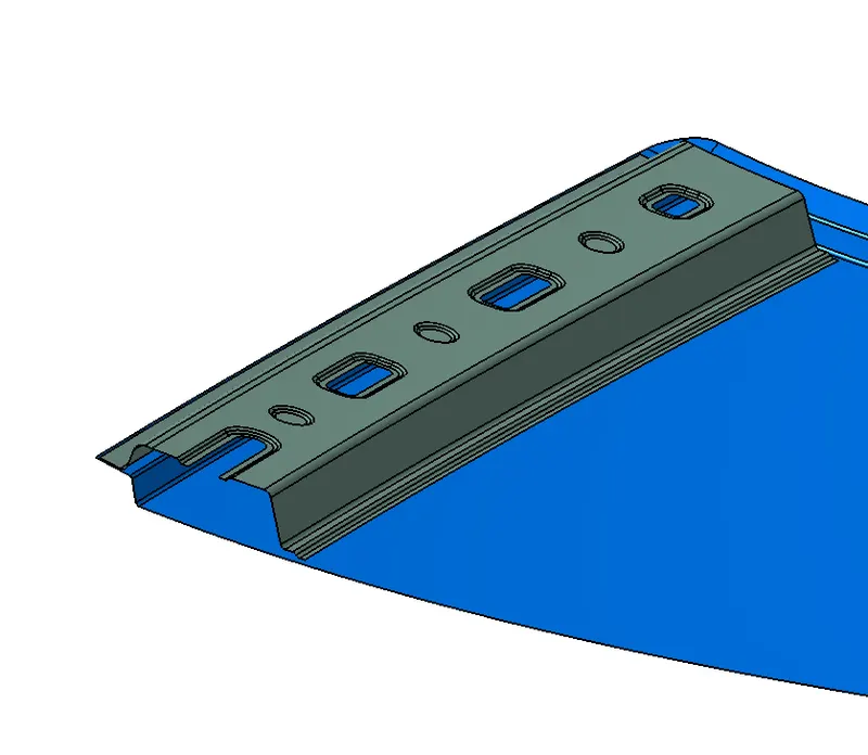
Fig 13: Creating embossments for the roof rail
g. The clearance between the flanges of the rails and the roof should be maintained as shown below for welding and assembling with mastics. The clearance has been provided considering the roof surface thickness as 0.75mm.
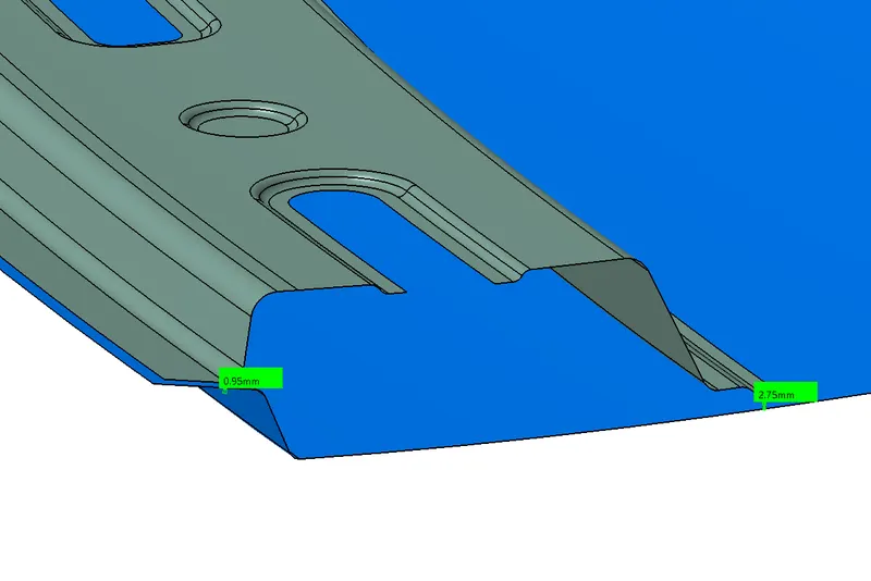
Fig 14:Clearence to be maintained.
h. Thus the construction for the front and the rear roof rail is as shown below.
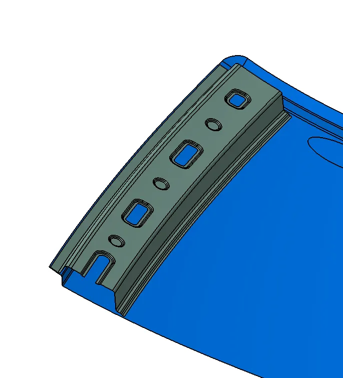
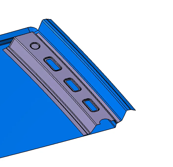
Fig 15: Front roof rail Fig 16: Rear roof rail.
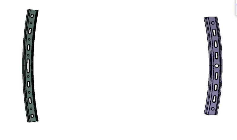
Fig 17: Front and rear roof rails.
- The roof bows are to be created after creating the roof rails. The bows are to be placed maintaining a distance of more than 300mm between each bow. There are 2 bows and a centre roof rail created for supporting the roof.
- The bows are to be constructed by following the steps shown below.
Fig 18: Master sketch for the bow.
a. The bow is to be constructed as shown in the master sketch with suitable measurements. Follow the steps done for constructing the rails.
b. The edges of the bow are to be shaped in such a way that it is suitable for assembling with the flanges of the roof by welding process. Maintain the clearance of 0.2mm between the roof flange and the bow flange.
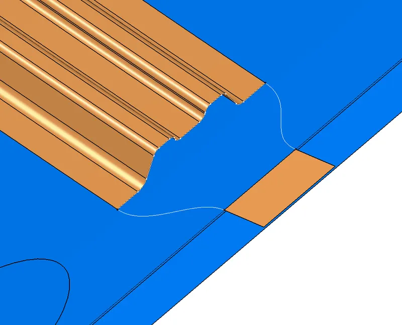
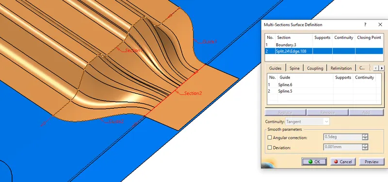
Fig 19: Construction of the bow edges. Fig 20: Using multi-section surface for filling surface.
c. The clearance between the bow flange and the roof should be between 3mm to 5mm.
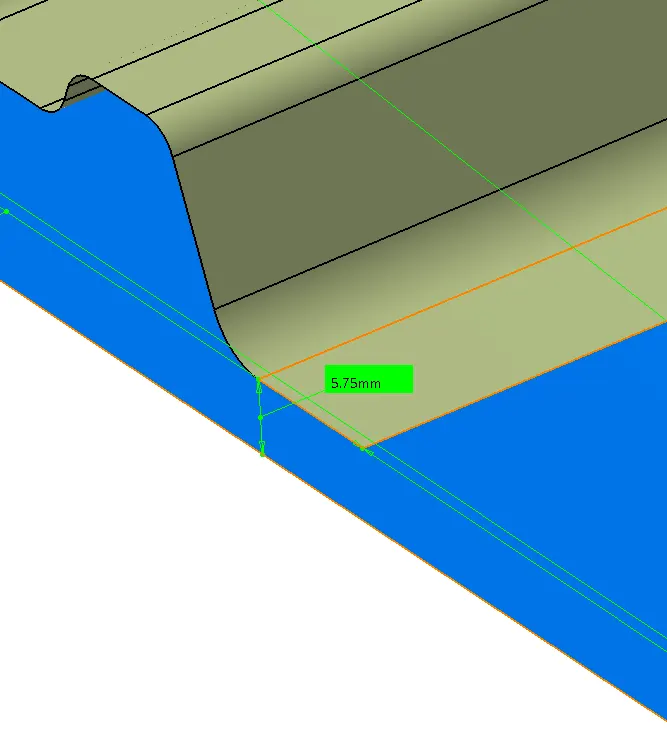
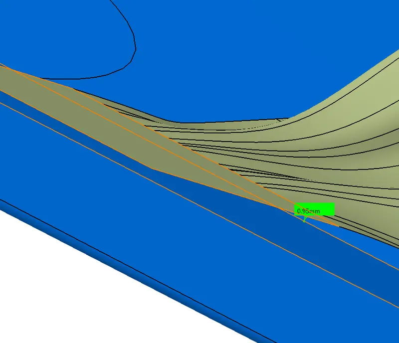
Fig 21: Clearance between the roof and the bow. Fig 22: Clearance between the roof and the bow flanges
d. Shape the edge flanges of the bow such that for the provision of assembling the mastic data to the roof.
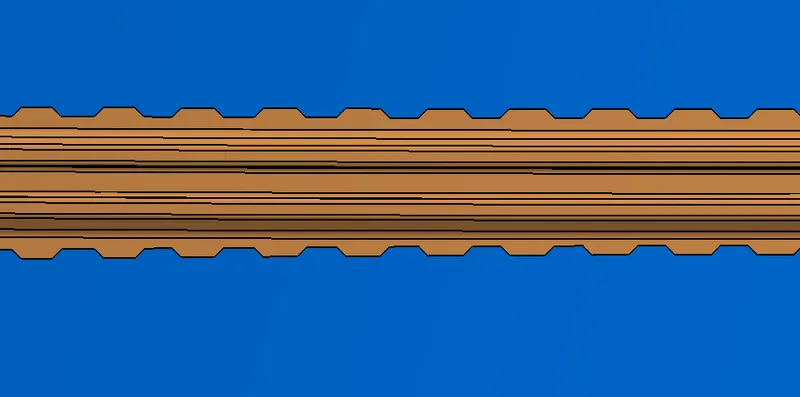
Fig 23: Shaping flanges for mastic data.
e. Maintain the width of the bow by more than 80mm.
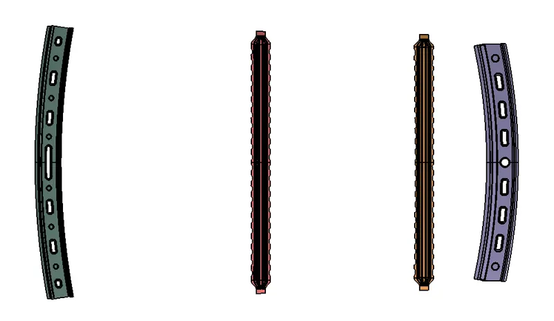
Fig 24: Construction of two bows
- The construction for the centre roof rail and the reinforcement is as shown below.
Fig 25: Master sketch for the center roof rail and reinforcement.
a. The centre roof rail is to be constructed as per the master sketch with suitable measurements. Follow the steps done for constructing the rails and the bow.
b. The edges of the centre roof rail are to be shaped as done for the bow edges. The clearance should also be maintained as done for the bow support.
c. The width for the centre roof rail should be more than 100mm.
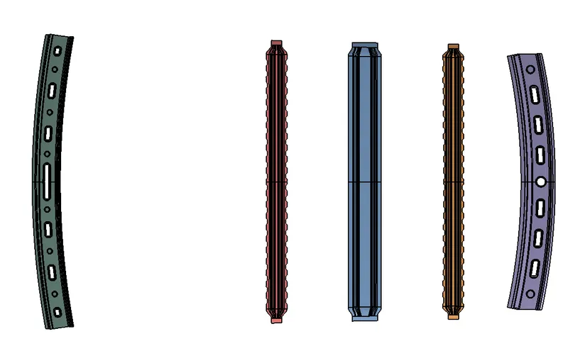
Fig 26: Center roof rail
d. Now create a reinforcement at the middle of the centre roof rail for the provision of assembling a roof light.
e. Follow the master sketch given with suitable measurements.
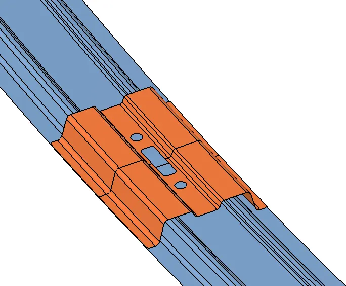
Fig 27:Center roof rail reinforcement.
f. The clearance between the centre roof rail and the reinforcement should be more than 5mm and 0.2mm between flanges of both the components.
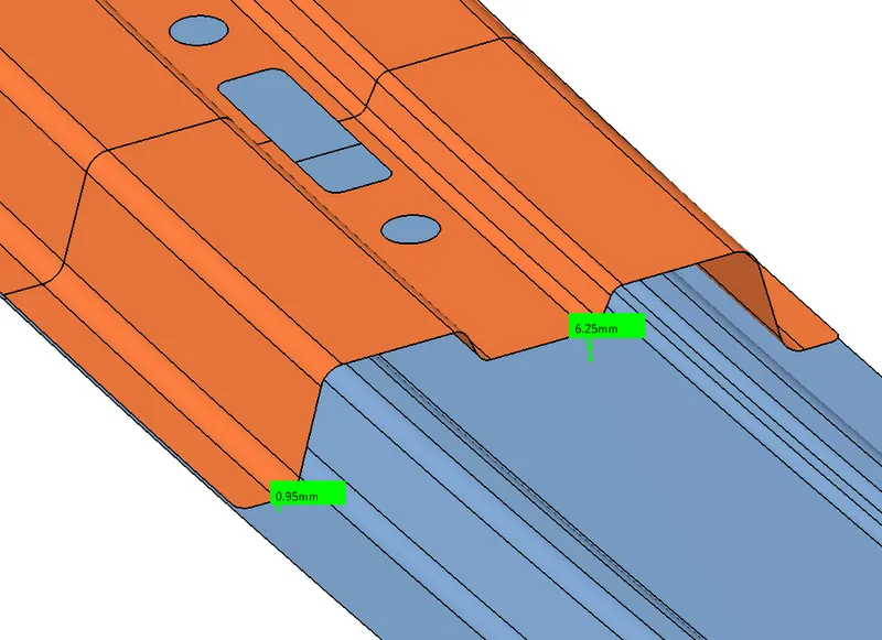
Fig 28: Clearance between the centre roof rail and the reinforcement.
- After creating the supports of the roof, create a cutout for the provision of a sunroof between the front roof rail and the bow.
- Provide flanges for the sunroof as provided on the edges of the roof.
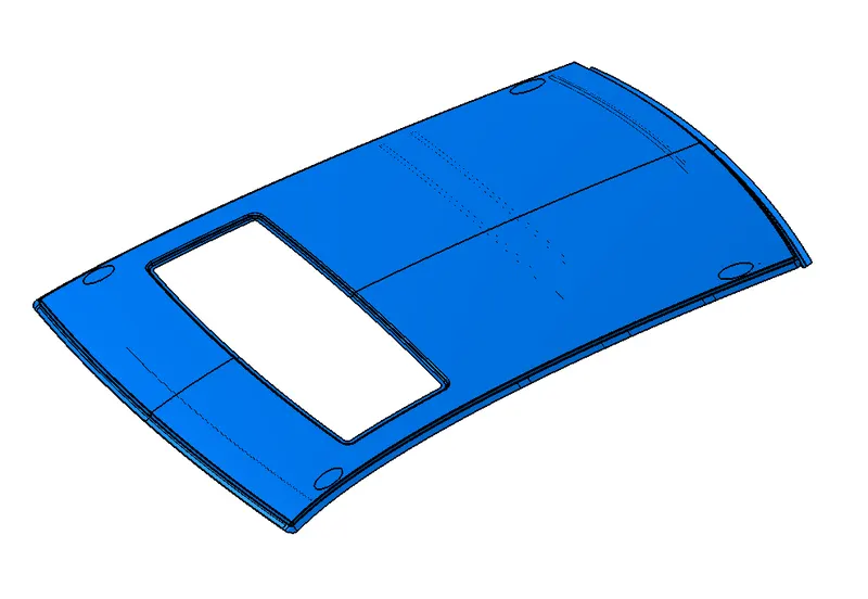
Fig 29: Provision of sunroof
9. Now the created surfaces are to be converted to solid sheet metal components. Using thicken option in the part body add thickness to each surface. The thickness for each component is as shown below.
(i) Roof - 0.75mm.
(ii) Front and rear roof rails - 1mm.
(iii) Bow 1 and Bow 2 - 1.2mm.
(iv) Center roof rail - 1.25mm.
(v) Rienforcement - 1.5mm.
10. Now a draft analysis is to be done for each component. Draft analysis on a component is usually performed to detect if the part which is drafted will be easily removed. This type of analysis is performed based on color ranges identifying zones on the analyzed element where the deviation from the draft direction at any point, corresponds to specified values. In case of sheet metal components the draft value is set to an angle of 7 degree clearance so that the manufacturablilty of the product is possible. The steps for performing a draft analysis is shown below.
a. Create a line perpendicular to the roof component i.e., in Y direction.
b. Enable the draft analysis option and place the compass on the created line.
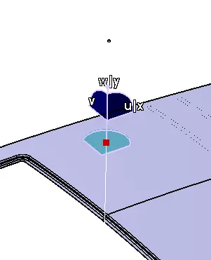
Fig 30: Placing compass for draft analysis.
c. Now click on the surface of the component, to view the draft analysis.
d. The surface in the upward direction shown be highlighted in green where as the sides and the bottom should be highlighted in blue and red colours respectively.
e. The draft analysis for the components are as shown below.
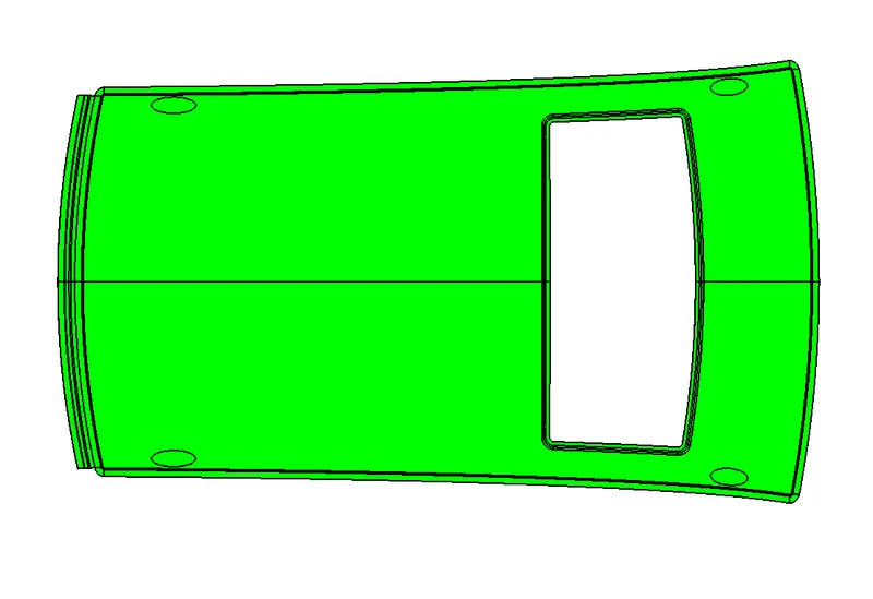
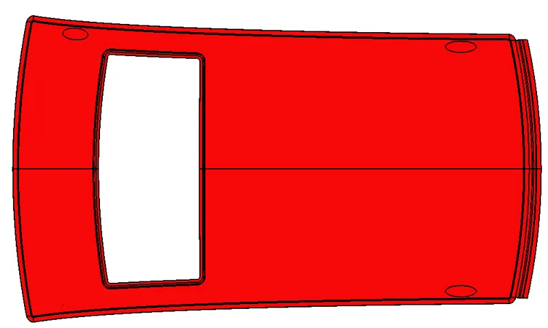

Fig 31: Roof draft analysis
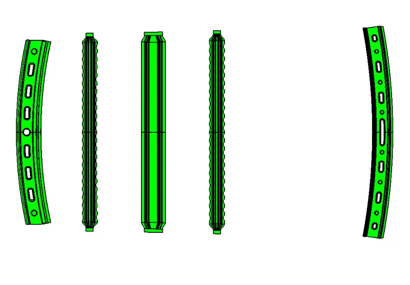
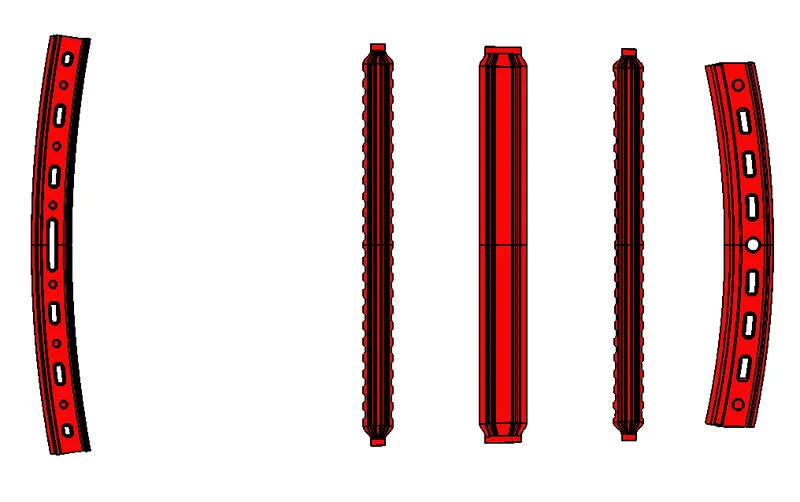
Fig 32: Draft analysis for the roof rails and bows.
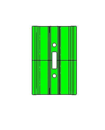
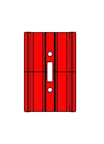
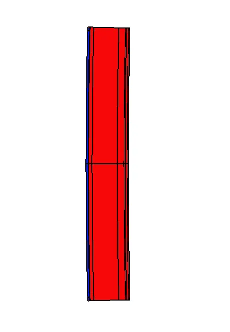
Fig 33: Draft analysis for reinforcement.
Now, analysis is to be done for the roof curvature, considering heat distortion criteria, section modulus and snow load criteria. The analysis is done for the roof structure as shown below.
Heat Distortion Criteria:
Heat distortion temperature is the temperature at which metal softens and deforms under a specified load. From Heat distortion criteria, roof strength can be enhanced by appropriate positioning of bow roof rails.
Bow – roof prediction Formula
W = [1.73 x 10^(-3) x L] + [1.85 x 10^(-8) x (R^2)/t] + [ 1.10x10^(-3) x l] - 2.68
Judgement Condition : OK< 2.7> 3.1
Where
L = Roof Length in X-Direction[mm](Roof dimension in 0-Y)
R = Roof curvature
R = 2(Rx*Ry)/(Rx+Ry)
Rx = X curvature
Ry = Y curvature
t = Roof plate thickness [mm]
l = Bow Roof Span [mm]
When the corresponding values are applied to the formula, the results gained are as shown below.
| S.No | BOW | Rx | Ry | R | I | L | t | `R^2/t` | W | OK/NG |
| 1. | Bow 2 - CR | 4268.073 | 9174.27 | 5825.837 | 242.731 | 2033.705 | 0.75 | 45253835.667 | 1.9425 | OK |
| 2. | CR - Bow 1 | 3643.675 | 12423.398 | 5634.731 | 246.774 | 2033.705 | 0.75 | 42333591.2564 | 1.8929 | OK |
| 3. | Bow 1 - RR | 3209.254 | 15179.434 | 5298.328 | 227.981 | 2033.705 | 0.75 | 37359095.0874 | 1.7802 | OK |
Section Modulus:
Section modulus is the ratio of total moment resisted by the section to the stress in the extreme fibre. It gives an idea about how much load the given structure can take. If the section modulus increases the moment of resistance increases and hence its load-bearing capacity.
Section modulus is calculated using the formula
S = I/y
where,
S = section modulus
I = moment of inertia
Y = distance between the neutral axis and extreme end of the object.
The section modules for each bow is as shown below.
Front roof rail:
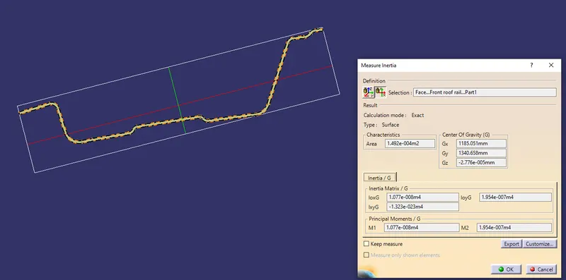
M1 = 1.077e-008`m^4`
I = 10770`mm^4`
y = `120.8/2`= 60.4
s = `I/y`= `10770/60.4`= 178.311`mm^3`
Bow 2:
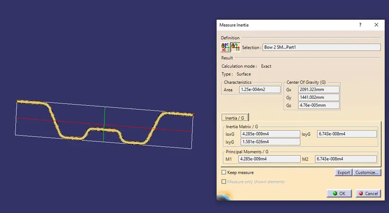
M1 = 4.285e-009`m^4`
I = 4285`mm^4`
y = `82.611/2`= 41.305`
S =`I/y`=`4285/41.305`=103.740`mm^3`
Center bow and Reinforcement:
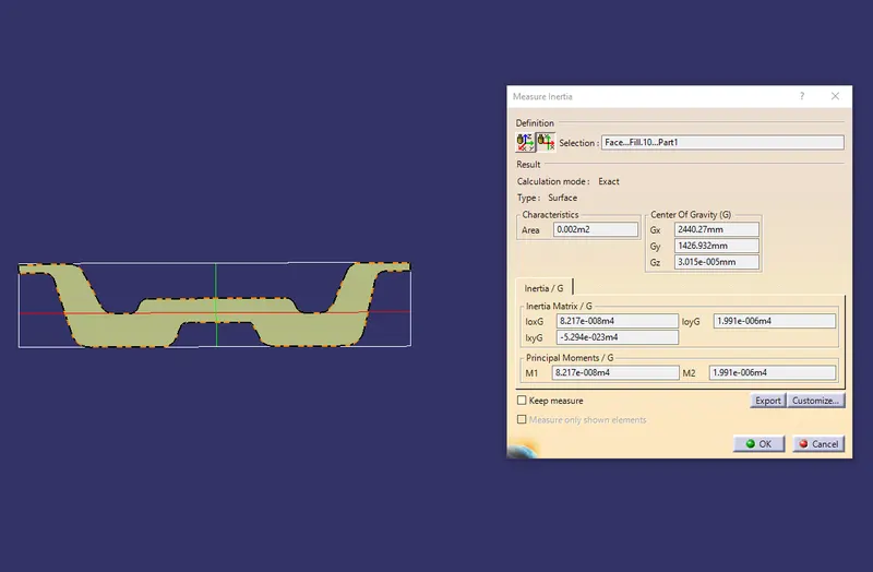
M1 = 8.217e-008`m^4`
I =82170`mm^4`
y = `130.533/2`= 65.2665`
`s `=`I/y`=`82170/65.2665`=1258.991`mm^3`
Bow 1:
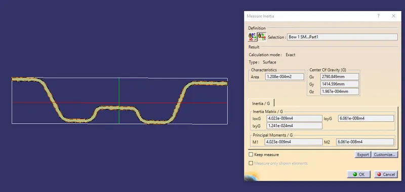
M1 = 4.023e-009`m^4`
I = 4023`mm^4`
y = `78.992/2`= 39.496`
`s `=`I/y`=`4023/39.496`=101.8584`mm^3`
Rear Roof rail:
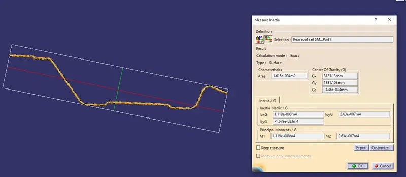
M1 = 1.119e-008`m^4`
I = 11190`mm^4`
y = `138.356/2`= 69.178`
`s `=`I/y`=`11190/69.178`=161.7566`mm^3`
Snow load Criteria:
The study on the ability of the roof to withstand the snowfall load and bouncing back to its original shape without any permanent deformation is
is called as snow load criteria.
Snow load Prediction formula
Qr = [Iy x t2] / [α x s x [(Rx + Ry)/2]2 x 10-8]
Note: The Qr value given over here is correct. There was a typo error in the formula given in the video.
Where
α = My x Lx2 x 10-12 , My = Y(Ly-Y)
Judgement condition = Qr ≥ 3.1
250 ≤ s ≤ 380
t = Roof plate thickness [mm]
Ly = Distance between the front and rear roof Rails on the Vehicle along with 0Y[mm]
Length of Roof panel with the center point between Roof rail Front /Rear as the reference point of the front and the rear.
Lx = Distance between the Left and Right end of the roof on the Roof BOW [mm]
Width of the roof panel exposed on the surface.
Y = Distance front Front Roof Rail to Roof BOW[mm]
s = Distance for which Roof BOW bears divided load [mm]
s = L1/2 + L2/2
Iy = Geometrical moment of inertia of Roof BOW (Y cross-section )[mm4]
Rx = Lateral direction curvature radius of roof panel Y cross-section on Roof BOW [mm]
Roof panel curvature Radius of the Length Lx in Front view
Ry = Longitudinal Direction curvature radius of the Roof panel X cross-section on Roof BOW [mm]
Roof panel X curvature radius of length s in Side view
When the corresponding values are applied to the formula, the results gained are as shown below.
| S.No | BOW | Ly | Lx | Iy | y | S | Rx | Ry | t | Qr | OK/NG |
| 1. | Bow 2 - C.R | 2033.705 | 1068.93 | 4285 | 349.417 | 349.522 | 4111.841 | 9400.397 | 0.75 | 22.468 | OK |
| 2. | C.R - Bow 1 | 2033.705 | 1054.124 | 7319 | 349.627 | 349.6605 | 4334.928 | 13441.916 | 0.75 | 22.7807 | OK |
| 3. | Bow 1- RR | 2033.705 | 1045.938 | 4023 | 349.904 | - | 3862.407 | 17231.047 | 0.75 | - |
Result:
Thus designing the roof and bows for the roof from the given styling surface is completed. The Heat Distortion Criteria, snow load criteria and section modulus for the roof are calculated.