Roof challenge
ROOF DESIGN
Aim: - To Develop the Roof flanges and reinforcement from the given styling surface.
About Roof
An automobile roof is a portion of an
Ditch Area
The Ditch Area is the extended portion
given
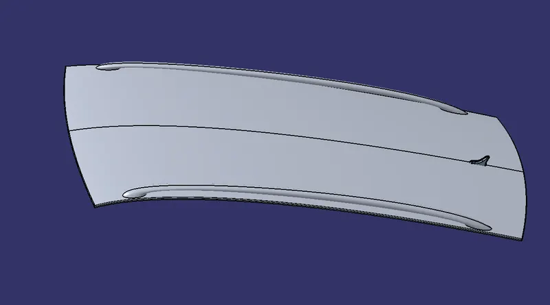
creating top surface and ditch area
offseting one side of the top surface
creating edges by using sweep command
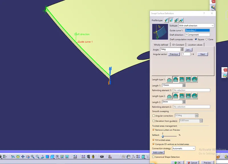
Ditch area
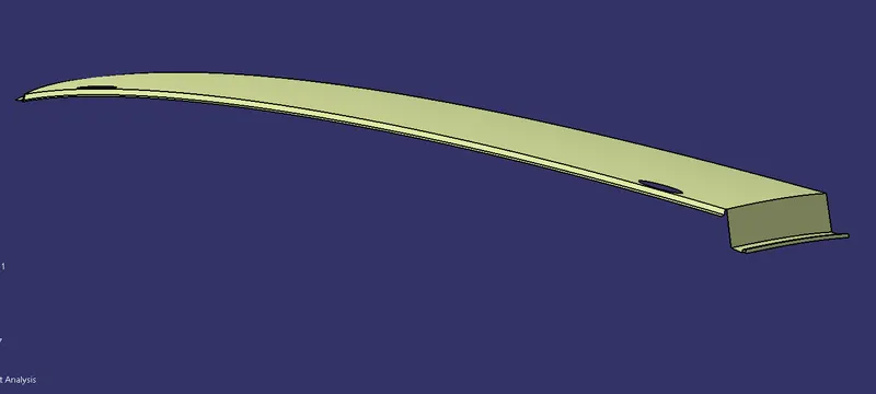
symmetry to other side and join
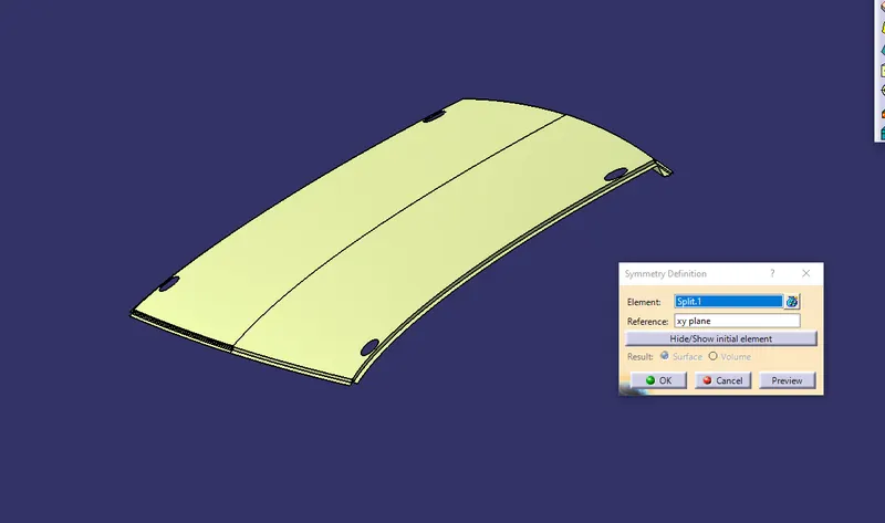
creating thick surface draft analysis
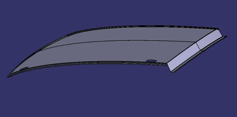
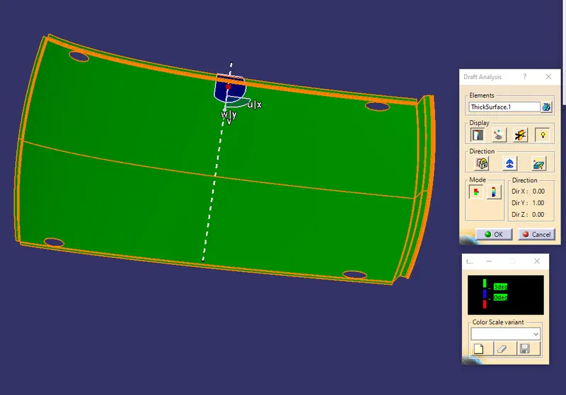
creating front rail
extract top surface and offseting
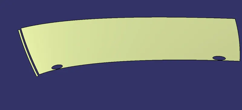
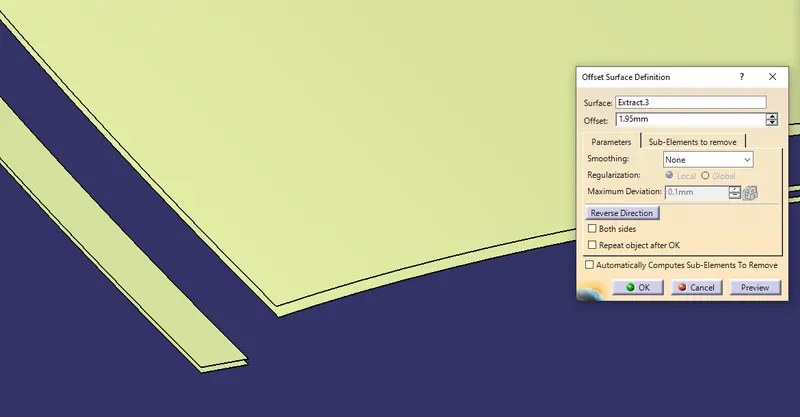
using parallel curve and split the top surface
then using sweep command creating front rail creating symmetry
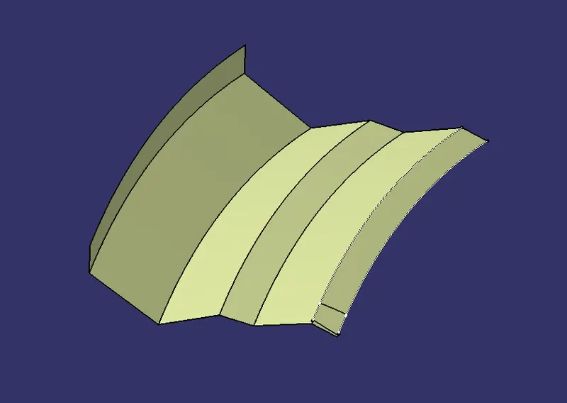
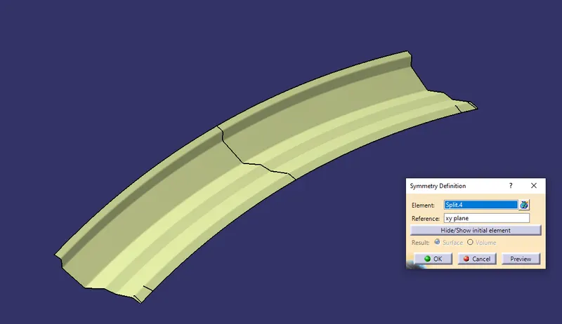
creating embosses
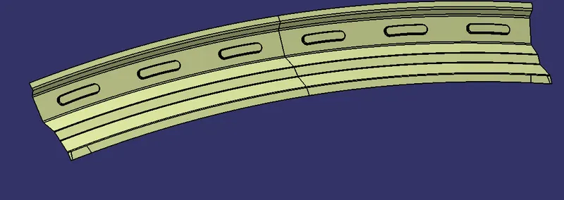
draft analysis
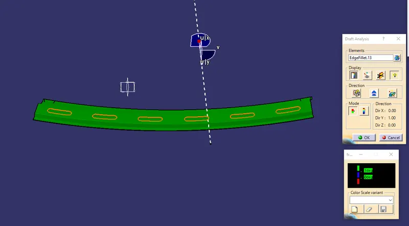
creating rear rail
same way of front rail creating rear rail giving thickness
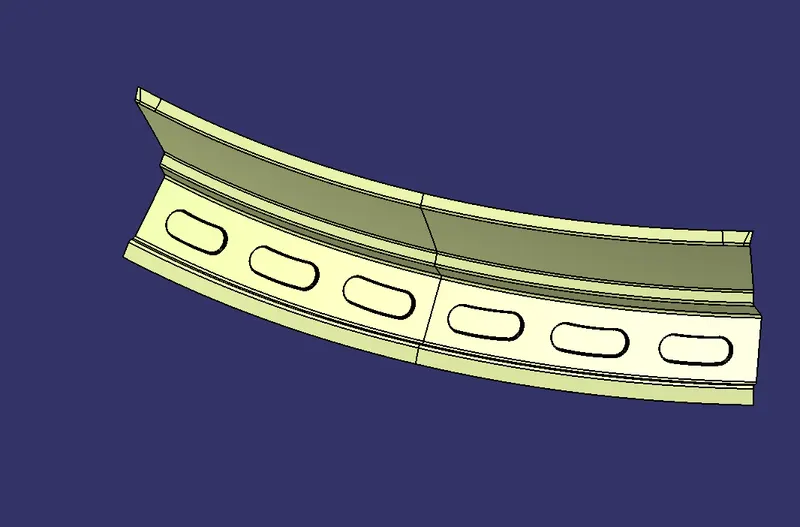
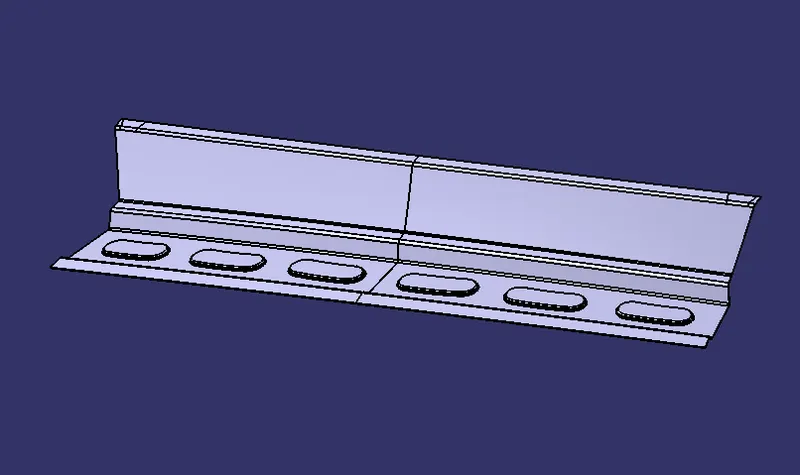
draft analysis
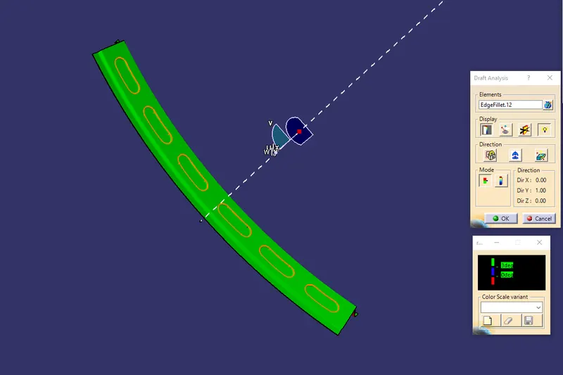
CREATING BOW ROOF 1
extracting top surface and giving offset then using sweep command creating bow roof 1
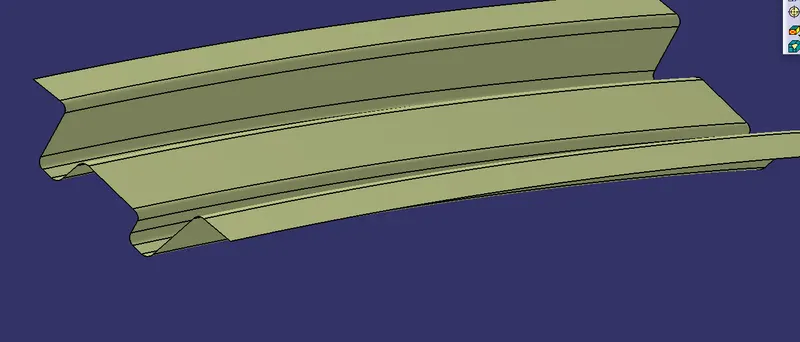
creating mastakes extruding the sketches and spliting
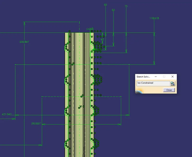
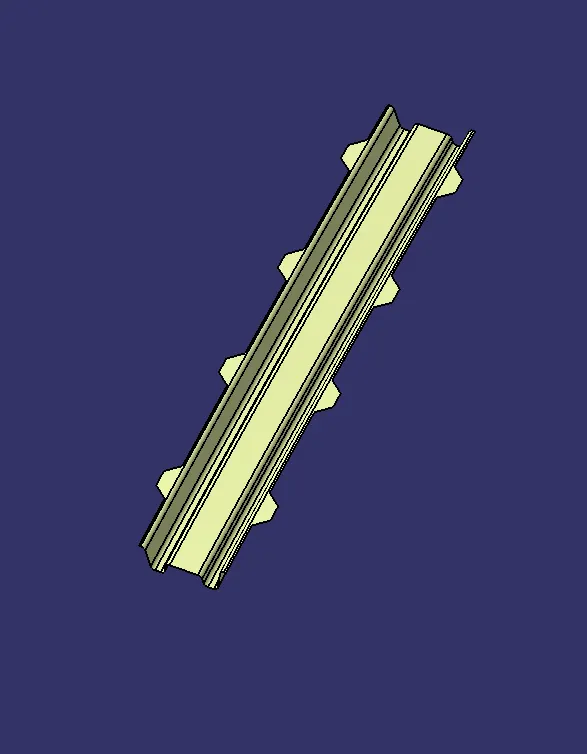
using MSS and create the part then join and symmetry
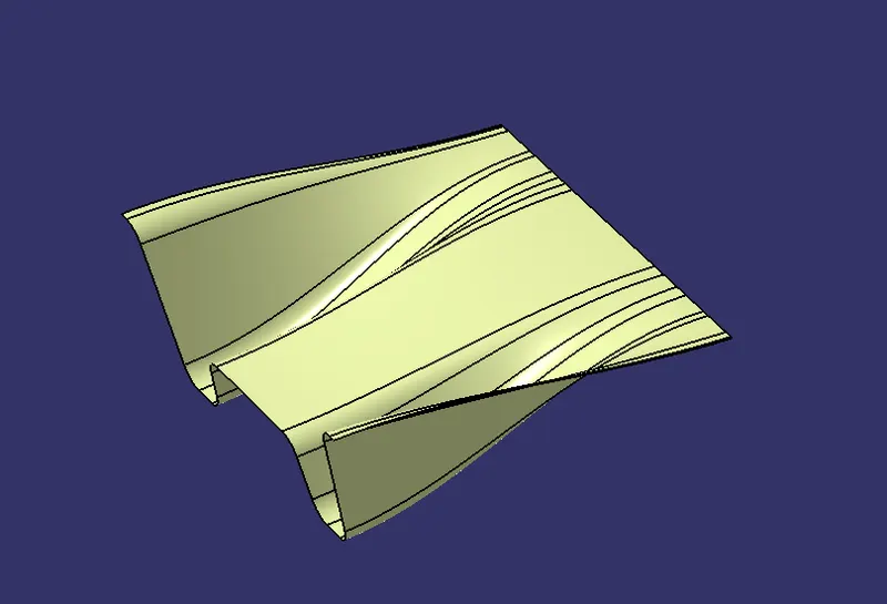
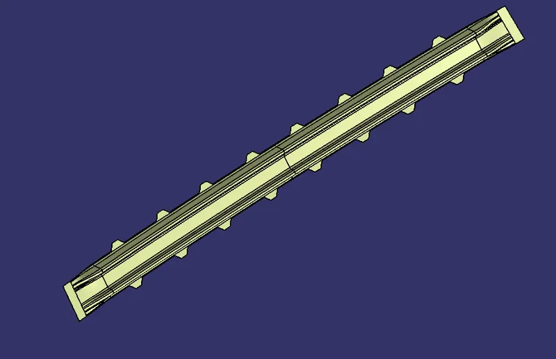
giving thickness Draft analysis
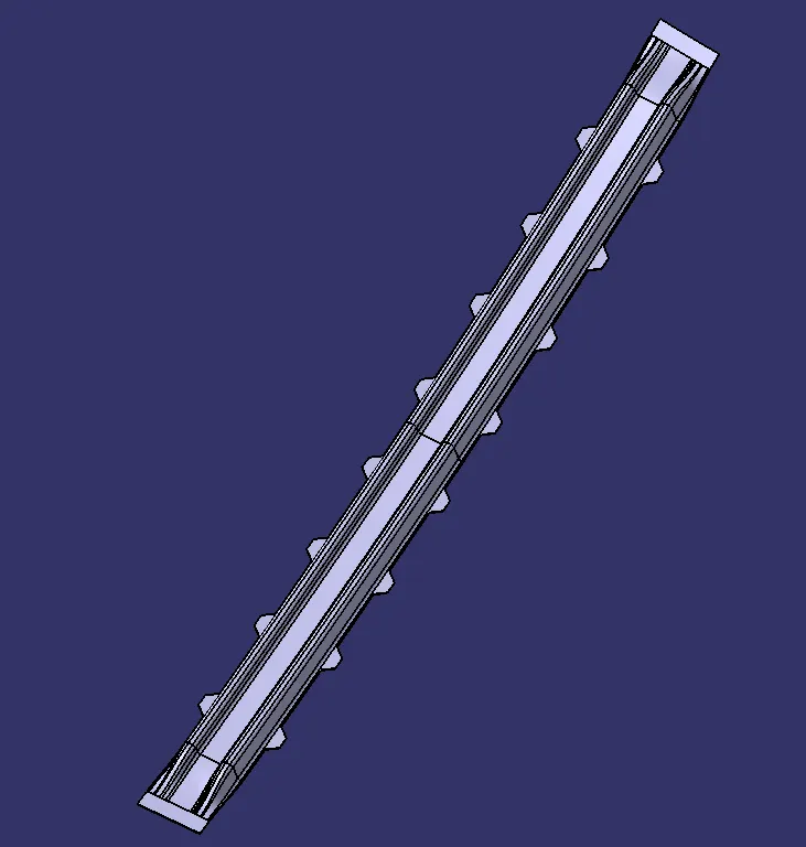
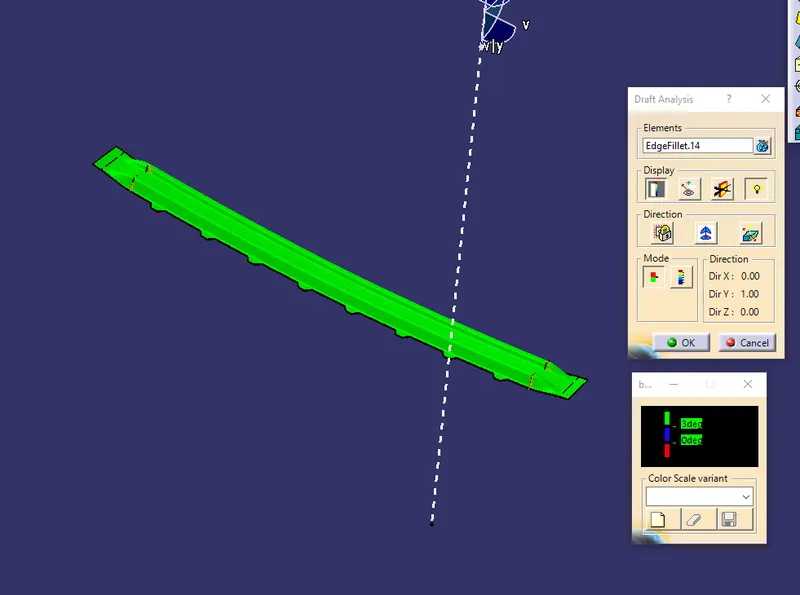
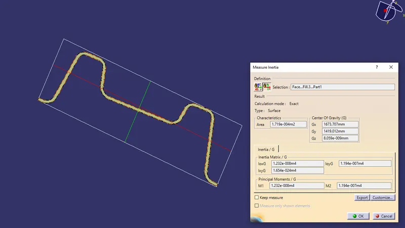
section modulus for bow roof 1
CREATING BOW ROOF 2
bow roof 1 and bow roof 2 are same procedures Draft analysis
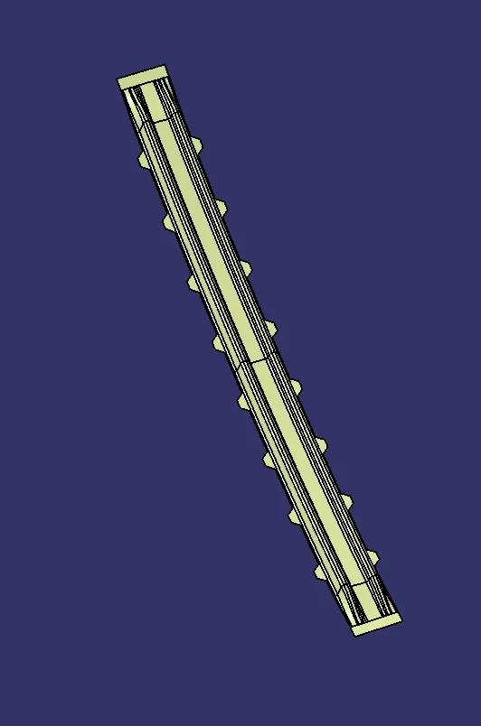
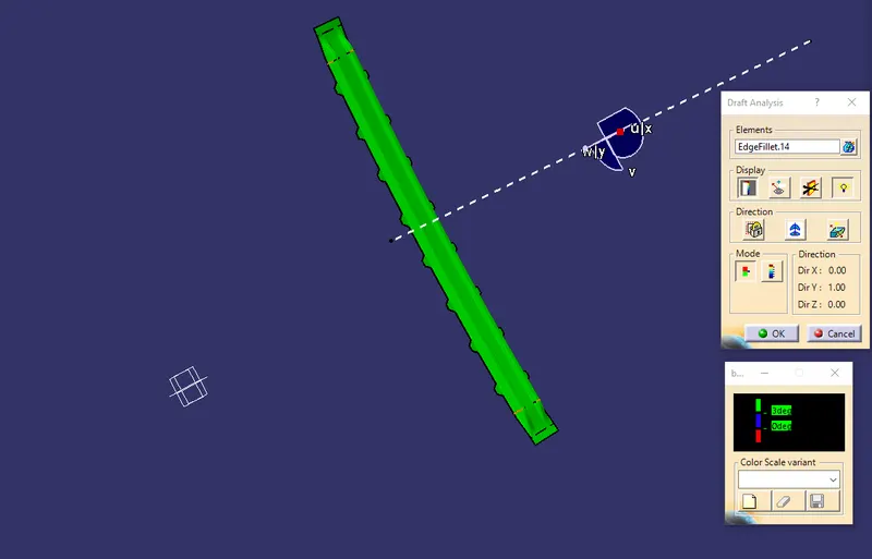
CREATING CENTRE BOW
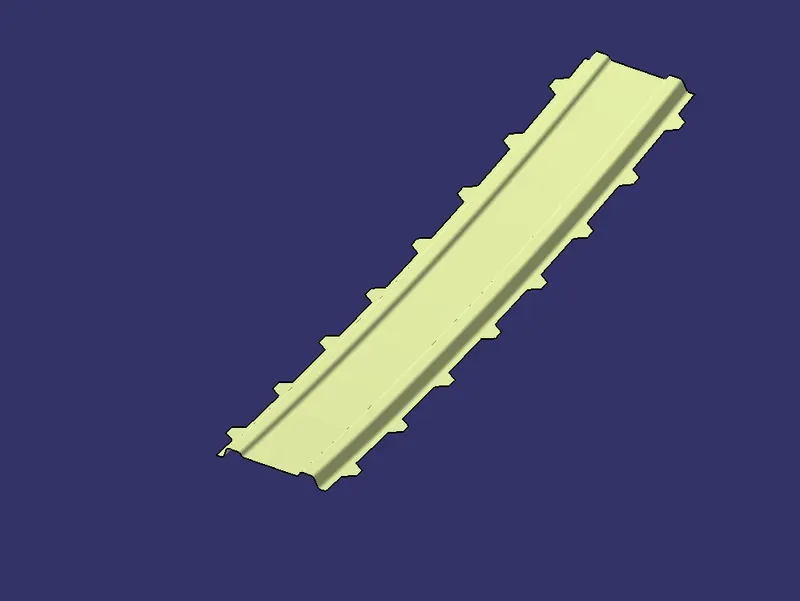
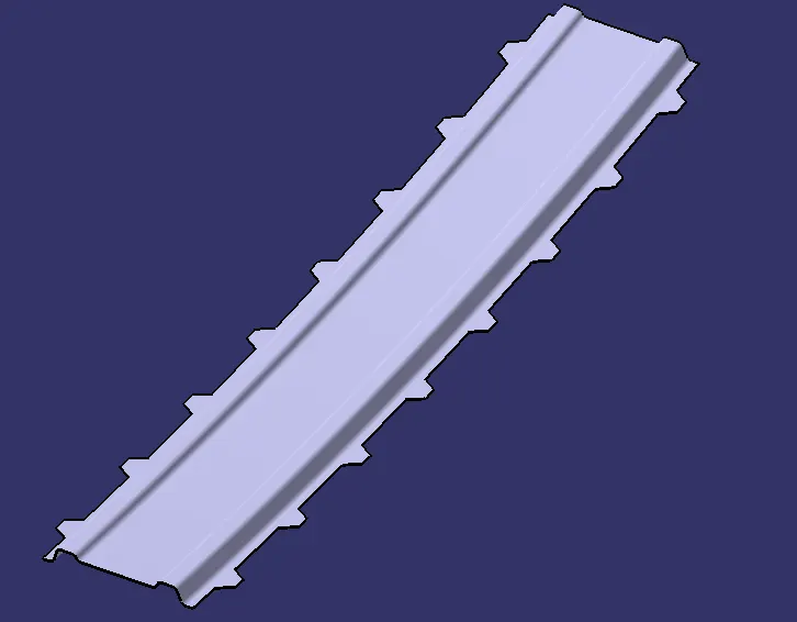
Draft analysis
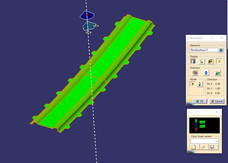
CREATING REINFORCEMENT CENTRE
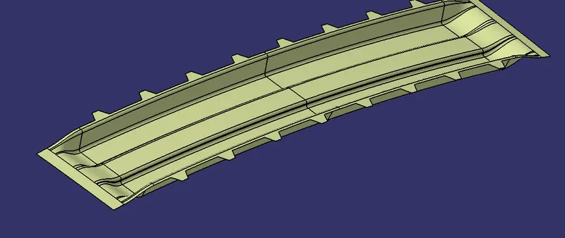
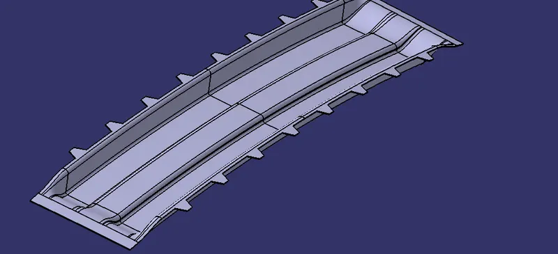
Draft analysis
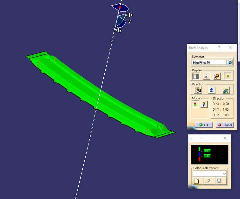
centre bow should not extended outside
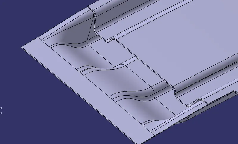
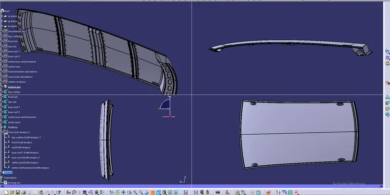
Multi views
SECTION MODULUS
section modulus for bow roof 1
------------------------------------------------------------------------------------------------------------------------------------------------------------------------------------------------------------------------
Product : Face...Fill.3...Part1
Date : Thursday, 15 April 2021 05:03:46
Author : Admin
------------------------------------------------------------------------------------------------------------------------------------------------------------------------------------------------------------------------
Component | Sub-Component | Area[m2] | Gx[mm] | Gy[mm] | Gz[mm] | M1[m4] | M2[m4] | IoxG[m4] | IoyG[m4] | IxyG[m4] |
------------------------------------------------------------------------------------------------------------------------------------------------------------------------------------------------------------------------
Face...Fill.3...Part1 | | 0.000171863 | 1673.707 | 1419.012 | 8.05856e-09 | 1.23205e-08 | 1.19439e-07 | 1.232e-008 | 1.194e-007 | 1.452e-019 |
------------------------------------------------------------------------------------------------------------------------------------------------------------------------------------------------------------------------
section modulus for centre bow and centre reinforcement
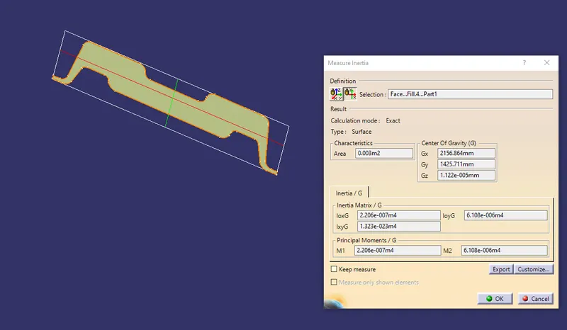
------------------------------------------------------------------------------------------------------------------------------------------------------------------------------------------------------------------------
Product : Face...Fill.4...Part1
Date : Thursday, 15 April 2021 05:16:36
Author : Admin
------------------------------------------------------------------------------------------------------------------------------------------------------------------------------------------------------------------------
Component | Sub-Component | Area[m2] | Gx[mm] | Gy[mm] | Gz[mm] | M1[m4] | M2[m4] | IoxG[m4] | IoyG[m4] | IxyG[m4] |
------------------------------------------------------------------------------------------------------------------------------------------------------------------------------------------------------------------------
Face...Fill.4...Part1 | | 0.003 | 2156.864 | 1425.711 | 1.12209e-05 | 2.20618e-07 | 6.10837e-06 | 2.206e-007 | 6.108e-006 | -8.627e-019 |
------------------------------------------------------------------------------------------------------------------------------------------------------------------------------------------------------------------------
section modulus for bow roof 2
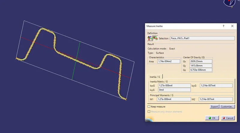
------------------------------------------------------------------------------------------------------------------------------------------------------------------------------------------------------------------------
Product : Face...Fill.5...Part1
Date : Thursday, 15 April 2021 05:22:20
Author : Admin
------------------------------------------------------------------------------------------------------------------------------------------------------------------------------------------------------------------------
Component | Sub-Component | Area[m2] | Gx[mm] | Gy[mm] | Gz[mm] | M1[m4] | M2[m4] | IoxG[m4] | IoyG[m4] | IxyG[m4] |
------------------------------------------------------------------------------------------------------------------------------------------------------------------------------------------------------------------------
Face...Fill.5...Part1 | | 0.000174006 | 2639.230 | 1415.060 | 6.75253e-06 | 1.26972e-08 | 1.21413e-07 | 1.27e-008 | 1.214e-007 | 2.604e-020 |
------------------------------------------------------------------------------------------------------------------------------------------------------------------------------------------------------------------------
CALCULATING HEAT DISTORTION CRITERIA
Bow – roof prediction Formula
W = [1.73 x 10^(-3) x L] + [1.85 x 10^(-8) x (R^2)/t] + [ 1.10x10^(-3) x l] - 2.68
Judgement Condition : OK< 3.1
Where
L = Roof Length in X-Direction[mm](Roof dimension in 0-Y)
R = Roof curvature
R = 2(Rx*Ry)/(Rx+Ry)
Rx = X curvature
Ry = Y curvature
t = Roof plate thickness [mm]
l = Bow Roof Span [mm]
CALCULATIONS:
1. FOR FRONT RAIL ROW TO BOW ROW 1
W = [1.73 x 10^(-3) x L] + [1.85 x 10^(-8) x (R^2)/t] + [ 1.10x10^(-3) x l] - 2.68
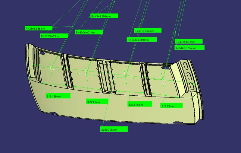
L = 2033.705mm
t = 0.75mm
Rx = 2803.388mm (by measuring the X-direction arc )
Ry = 5759.619mm (by measuring the Y-direction arc)
l = 313.199mm (distance between extreme ends of front rail row and bow row 1)
R = 2(Rx*Ry)/(Rx+Ry)
= 2(2803.388*5759.619)/(2803.388+5759.619)
= 3771.209mm
(R^2)/t = (3771.209^2)/0.75
= 18962689.762
W = [1.73 x 10^(-3) x 2033.705] + [1.85 x 10^(-8) x 18962689.762] + [1.10 x 10^(-3) x 313.199] - 2.68
= 1.532
so the value is less than 3.1
Judgement Condition : OK< 3.1
2. BOW ROOF 1 & CENTRE REINFORCEMENT
W = [1.73 x 10^(-3) x L] + [1.85 x 10^(-8) x (R^2)/t] + [ 1.10x10^(-3) x l] - 2.68
L = 2033.705mm
t = 0.75mm
Rx = 4946.194mm (by measuring the X-direction arc )
Ry = 6306.001mm (by measuring the Y-direction arc)
l = 329.33mm (distance between extreme ends of bow row 1 & centre reinforcement)
R = 2(Rx*Ry)/(Rx+Ry)
= 2(4946.194*6306.001)/(4946.194+6306.001)
= 5543.932mm
(R^2)/t = (5543.932^2)/0.75
= 40980245.774
W = [1.73 x 10^(-3) x 2033.705] + [1.85 x 10^(-8) x 40980245.774] + [1.10 x 10^(-3) x 329.33] - 2.68
= 1.958
so the value is less than 3.1
Judgement Condition : OK< 3.1
3. CENTRE REINFORCEMENT & BOW ROOF 2
W = [1.73 x 10^(-3) x L] + [1.85 x 10^(-8) x (R^2)/t] + [ 1.10x10^(-3) x l] - 2.68
L = 2033.705mm
t = 0.75mm
Rx = 4012.304mm (by measuring the X-direction arc )
Ry = 10436.981mm (by measuring the Y-direction arc)
l = 329.37mm (distance between extreme ends of centre reinforcement & bow roof 2)
R = 2(Rx*Ry)/(Rx+Ry)
= 2(4012.304*10436.981)/(4012.304+10436.981)
= 5796.320mm
(R^2)/t = (5796.320^2)/0.75
= 44796434.910
W = [1.73 x 10^(-3) x 2033.705] + [1.85 x 10^(-8) x 44796434.910] + [1.10 x 10^(-3) x329.37] - 2.68
= 2.006
so the value is less than 3.1
Judgement Condition : OK< 3.1
4. BOW ROOF 2 & REAR ROOF ROW
W = [1.73 x 10^(-3) x L] + [1.85 x 10^(-8) x (R^2)/t] + [ 1.10x10^(-3) x l] - 2.68
L = 2033.705mm
t = 0.75mm
Rx = 3324.853mm (by measuring the X-direction arc )
Ry = 14407.706mm (by measuring the Y-direction arc)
l = 315.32mm (distance between extreme ends of bow roof 2 &rear roof row)
R = 2(Rx*Ry)/(Rx+Ry)
= 2(3324.853*14407.706)/(3324.853+14407.706)
= 5402.886mm
(R^2)/t = (5402.886^2)/0.75
= 38921575.302
W = [1.73 x 10^(-3) x 2033.705] + [1.85 x 10^(-8) x 38921575.302] + [1.10 x 10^(-3) x315.32] - 2.68
= 1.904
so the value is less than 3.1
Judgement Condition : OK< 3.1
Table for all the values of Heat distortion criteria:
| S.NO | POSITIONS | Rx (mm) | Ry (mm) | R (mm) | l (mm) | L (mm) | t (mm) | R^2/t | W | OK/NG |
| 1 | FRR & BR1 | 5759.619 | 2803.388 | 3771.209 | 313.199 | 2033.705 | 0.75 | 18962689.762 | 1.532 | OK |
| 2 | BR1 & CR | 4946.194 | 6306.001 | 5543.932 | 329.33 | 2033.705 | 0.75 | 40980245.774 | 1.958 | OK |
| 3 | CR & BR2 | 4012.304 | 10436.981 | 5796.320 | 329.37 | 2033.705 | 0.75 | 44796434.910 | 2.006 | OK |
| 4 | BR2 & RRR | 3324.853 | 14407.706 | 5402.886 | 315.32 | 2033.705 | 0.75 | 38921575.302 | 1.904 | OK |
CALCULATING SNOW LOAD CRITERIA
Snow load Prediction formula
Qr = [Iy x t2] / [α x s x [(Rx + Ry)/2]2 x 10-8]
Where
α = My x Lx2 x 10-12 , My = Y(Ly-Y)
Judgement condition = Qr ≥ 3.1
250 ≤ s ≤ 380
t = Roof plate thickness [mm]
Ly = Distance between the front and rear roof Rails on the Vehicle along with 0Y[mm]
Length of Roof panel with the center point between Roof rail Front /Rear as the reference point of the front and the rear.
Lx = Distance between the Left and Right end of the roof on the Roof BOW [mm]
Width of the roof panel exposed on the surface.
Y = Distance front Front Roof Rail to Roof BOW[mm]
s = Distance for which Roof BOW bears divided load [mm]
s = L1/2 + L2/2
Iy = Geometrical moment of inertia of Roof BOW (Y cross-section )[mm4]
Rx = Lateral direction curvature radius of roof panel Y cross-section on Roof BOW [mm]
Roof panel curvature Radius of the Length Lx in Front view
Ry = Longitudinal Direction curvature radius of the Roof panel X cross-section on Roof BOW [mm]
Roof panel X curvature radius of length s in Side view
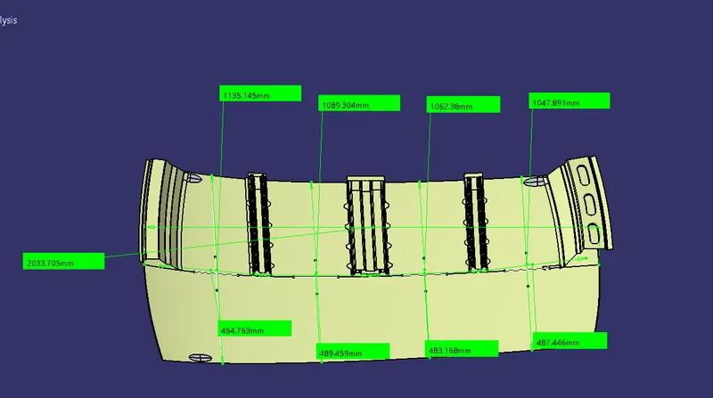
Lx , Ly and Y values
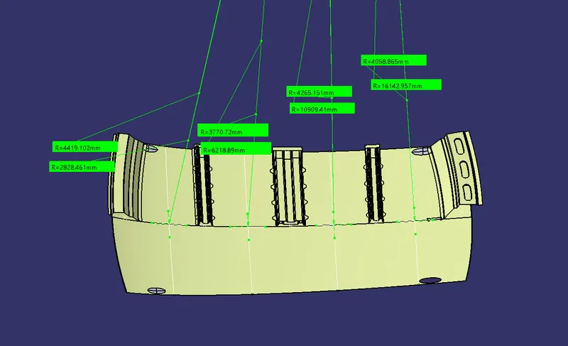
Rx and Ry values
CALCULATIONS
1. FOR FRONT RAIL AND BOW ROW 1
Qr = [Iy x t2] / [α x s x [(Rx + Ry)/2]2 x 10-8]
α = My x Lx2 x 10-12
My = Y(Ly-Y)
s = L1/2 + L2/2
Where
Rx = 4419.102mm
Ry = 2828.46mm
Lx = 1135.145mm
Ly = 2033.705mm
Y = 454.763mm
t = 0.75mm
Iy = 1.23 x 10^4
My = 454.763(2033.705-454.763)
= 718044.400mm
α = 718044.400 x (1135.145)^2 x 10^-12
= 0.925
s = L1/2 + L2/2
L1 = 454.763mm
L2 = 489.459mm
s = (454.763/2) + (489.459/2)
= 472.111mm
Qr = [1.23 x 10^4 x 0.75^2] / [0.925 x 472.111 x[(4419.102+2828.46)/2]^2 x 10^-8
= 120.649
Judgement condition = Qr ≥ 3.1
The Qr value is greater than 3.1
2. FOR BOW ROOF 1 AND CENTRE REINFORCEMENT
Qr = [Iy x t2] / [α x s x [(Rx + Ry)/2]2 x 10-8]
α = My x Lx2 x 10-12
My = Y(Ly-Y)
s = L1/2 + L2/2
Where
Rx = 3770.72mm
Ry = 6218.89mm
Lx = 1089.304mm
Ly = 2033.705mm
Y = 489.459mm
t = 0.75mm
Iy = 2.206 x 10^5
My = 489.459(2033.705-489.459)
= 755845.102mm
α = 755845.102 x (1089.304)^2 x 10^-12
= 0.896
s = L1/2 + L2/2
L1 = 489.459mm
L2 = 483.168mm
s = (489.459/2) + (483.168/2)
= 486.313mm
Qr = [2.206 x 10^5 x 0.75^2] / [0.896 x 486.313 x[(3770.72+6218.89)/2]^2 x 10^-8
=1141.485
Judgement condition = Qr ≥ 3.1
the value is greater than 3.1
3. CENTRE REINFORCEMENT & BOW ROOF 2
Qr = [Iy x t2] / [α x s x [(Rx + Ry)/2]2 x 10-8]
α = My x Lx2 x 10-12
My = Y(Ly-Y)
s = L1/2 + L2/2
Where
Rx = 4265.151mm
Ry = 10901.41mm
Lx = 1062.38mm
Ly = 2033.705mm
Y = 483.168mm
t = 0.75mm
Iy = 1.27 x 10^4
My = 483.168(2033.705-483.168)
= 749169.861mm
α = 749169.861 x (1062.38)^2 x 10^-12
=0.845
s = L1/2 + L2/2
L1 = 483.168mm
L2 = 487.446mm
s = (483.168/2) + (487.446/2)
=485.307mm
Qr = [1.27 x 10^4 x 0.75^2] / [0.845 x 485.307 x[(4265.151+10901.41)/2]^2 x 10^-8
= 30.294
Judgement condition = Qr ≥ 3.1
the value is greater than 3.1
table for all the values of snow load criteria
| S. NO | POSITION | Rx (mm) | Ry (mm) | Lx (mm) | Ly (mm) | t (mm) | Y (mm) | My = Y(Ly-Y) (mm) | α = My x Lx2 x 10-12 | L1(mm) | L2 (mm) | s = L1/2 + L2/2 | Iy (mm^4) | Qr | OK/NG |
| 1 | FRR & BR1 | 4419.102 | 2828.46 | 1135.145 | 2033.705 | 0.75 | 454.763 | 718044.400 | 0.925 | 454.763 | 489.459 | 472.111 | 1.23*10^4 | 120.64 | OK |
| 2 | BR1 & CR | 3770.72 | 6218.89 | 1089.304 | 2033.705 | 0.75 | 489.459 | 755845.102 | 0.896 | 489.459 | 483.168 | 486.313 | 2.206*10^5 | 1141.48 | OK |
| 3 | CR & BR 2 | 4265.151 | 10901.41 | 1062.38 | 2033.705 | 0.75 | 483.168 | 749169.861 | 0.845 | 483.168 | 487.446 | 485.307 | 1.27*10^4 | 30.294 | OK |
| 4 | BR2 & RRR | 4058.865 | 16142.957 | 1047.891 | 2033.705 | 0.75 |