REVIT_ Plan, 3D View & Structural Drawings_Project 2
1) Select the type of structure you want to build from one of the three below
- Multi Unit Residential Apartment
- Office Buildings
- School
Ans. I want to build multi unit residential apartment from the given three options.
2) Assume reasonable assumptions for geographic and location details for your project modelling. Based on assumptions and type of structure selected, identify the modelling requirements from NBC
Ans. I have made following assumptions for geographic and location details :-
- My project is in plain area
- It is in residential area
- Road width infront of my apartment is 70ft
The modeling requirements from NBC are :
- An exit must be provided in every building, so as to permit safe escape of residents in times of fire accidents or earthquakes
- The minimum height of basement should be 2.5m and the maximum height shouldd be 4.5m
- Minimum length and width of rooms as per NBC V-1
3) Using the structural model, include the following components based on the type of structure selected
- Foundation - Isolates/wall/Matt Foundation
- Columns
- Beams connected to columns
- Roof framing/Truss
- Floor/ Decks
- Floor openings for elevators and stairs
Ans.
AIM : To include components into the model by using structural model, based on type of structure selected
TOOLS USED :
- New
- Save
- Grids
- Specify coordinates
- Levels
- Columns
- Isolated foundation
- Beams
- Structural floor
- Shaft
PROCEDURE :
- Open revit
- Open new project file choosing structural template
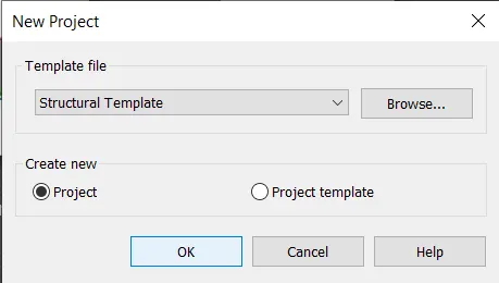
- Save it with an appropriate name
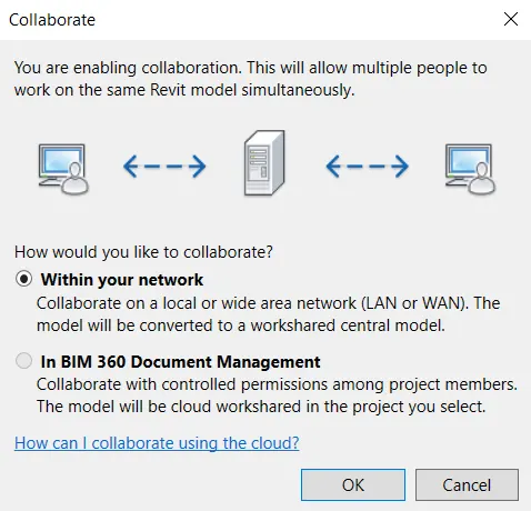
- Go to collaborate tab and select collaborate command to do collaboration and make it as central model
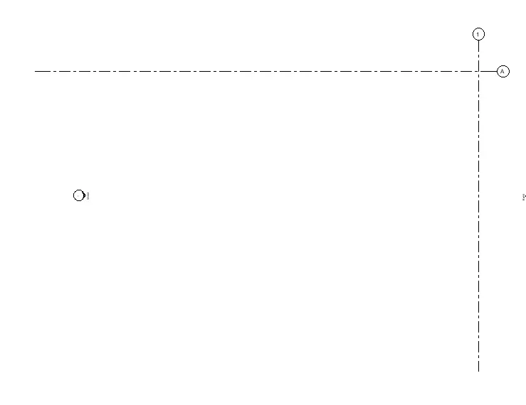
- Go to structural tab and select grids command to draw longitudinal and transverse grids

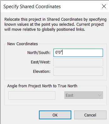
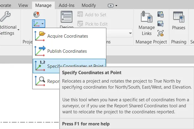
- Go to manage tab and click on coordinates then select specify coordinates

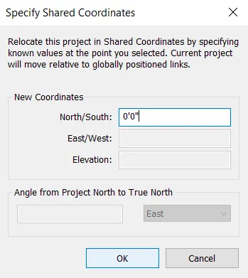
- Specify the coordinates as 0'0" for both grids and save the file and close
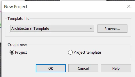
- Now open another new poject file choosing architectural template and save the file with appropriate name
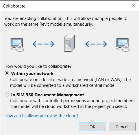
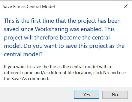
- Go to collaborate tab and do the collaboration and make it as central model
- Go to architecture tab and select grids command to draw longitudinal and transverse grids

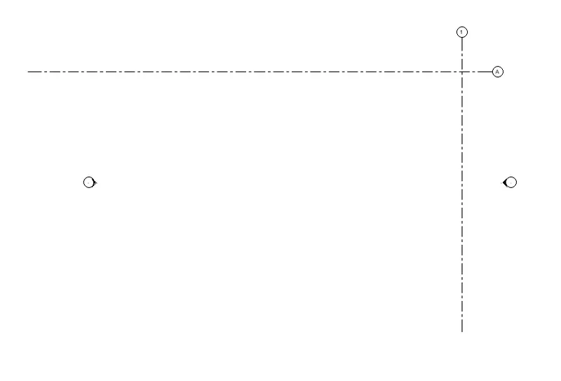
- Go to manage tab and select specify coordinates as 0'0" for both grids
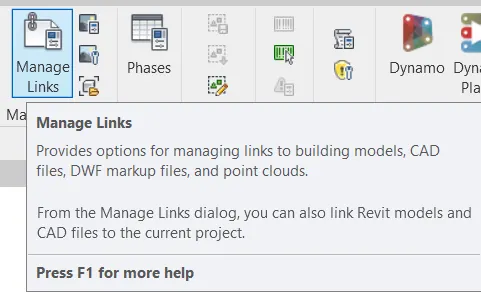
- Now click on manage links to link the structural model to the architectural model
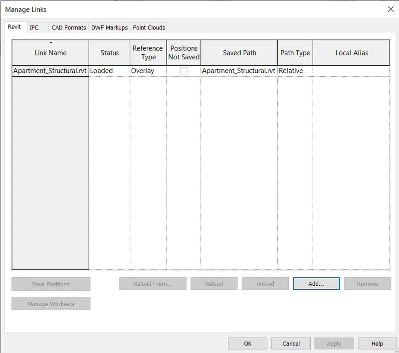
- Both grids will appear in the same model
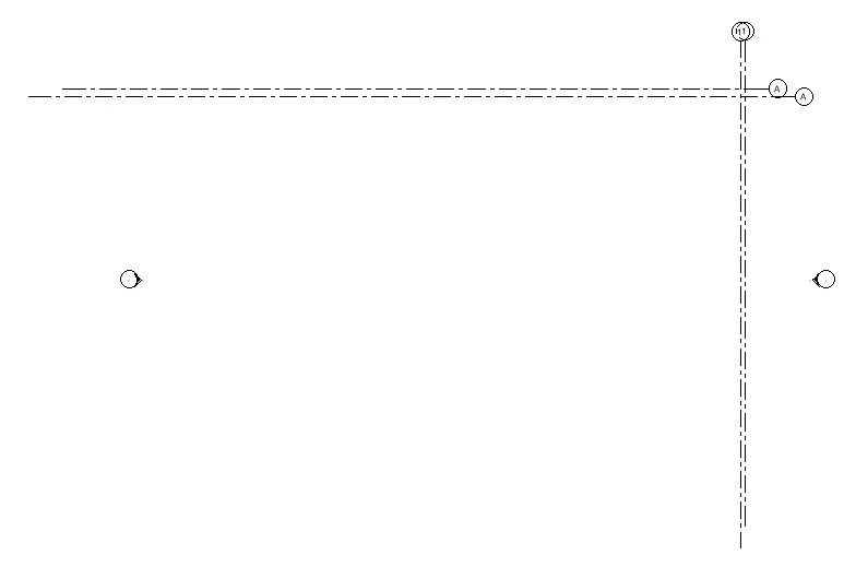
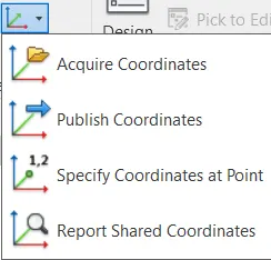
- Now click on acquire coordinates command to acquire the coordinates of linked grids
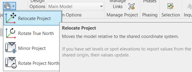
- Click on relocate project to move the grids and to overlap them on each other to continue with the project
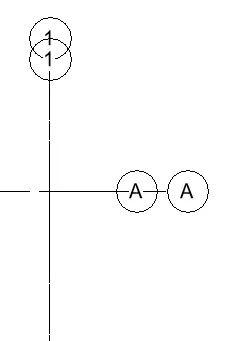
- Save the project and close
- Open Structural model again
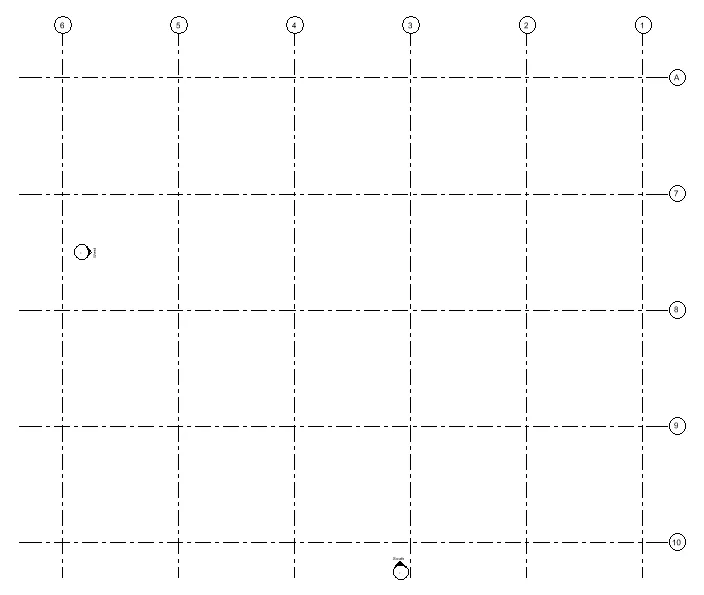
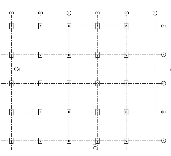
- Draw longitudinal and transverse grids at equal interval (say 30')
- Click on elevation and draw the levels at equal interval (say 12' 0") from one floor to other
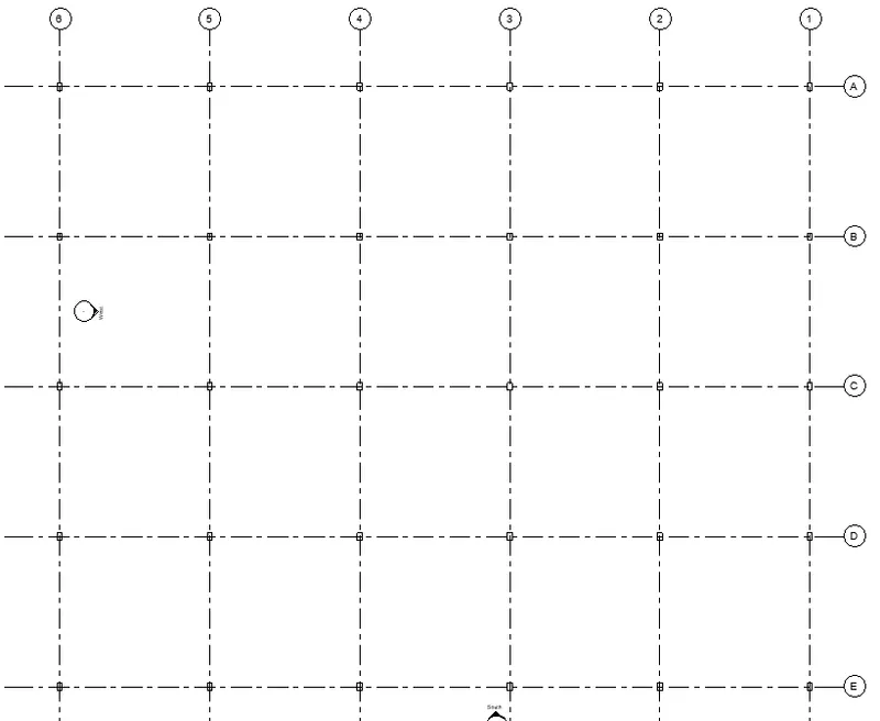
- Draw columns at grids and edit the properties using project browser

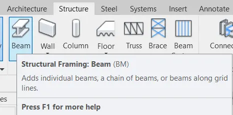
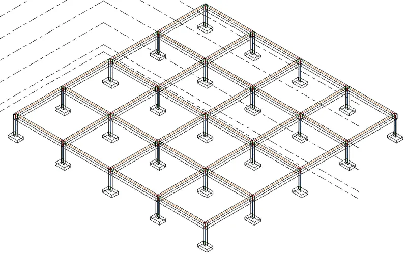
- Select beams command and draw beams connected to columns and change the constraint as first floor instead of ground floor
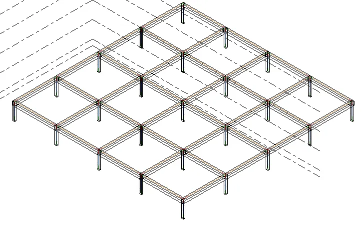
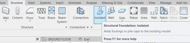
- Add isolated foundation to the columns at foundation level
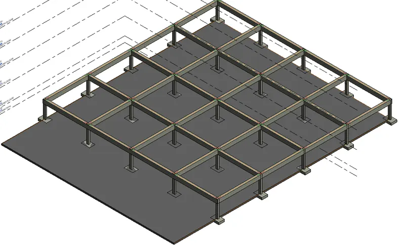
- Draw floor using floor command
- Copy the elements and align it to the selected levels
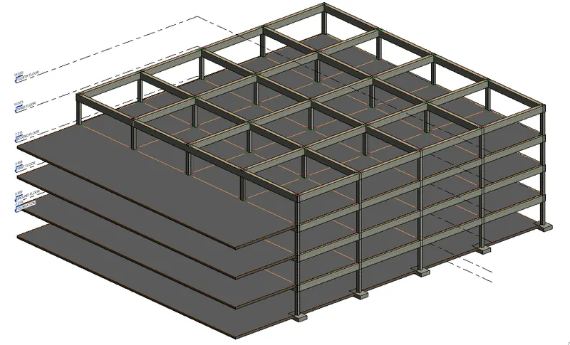
- Now select shaft command from structure tab for lift and staircase openings

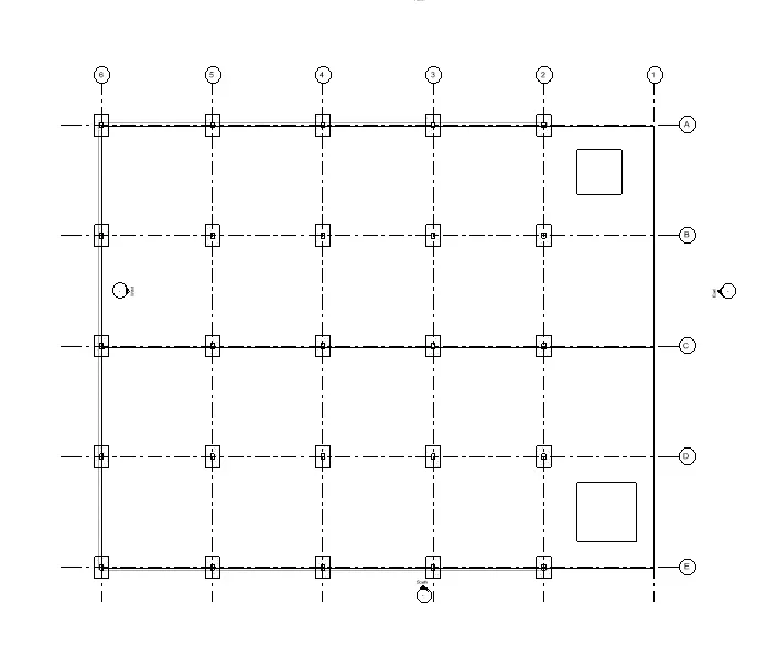
RESULT : A structural model included given components like foundation, columns, beams connected to columns, floor, shaft for lift and staircase openings
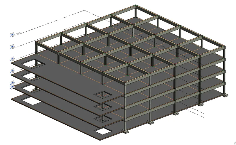
4) Using the architectural model, include the following components based on the type of structure selected
- Wall layout with appropriate material and finishing
- Exterior facade with fancy finishing
- Interior partition walls to size rooms
- Components to add details to room (Desk, Chair, Lighting, Plumbing fixtures)
- Add components such as stairs, elevators
- Have atleast one side of building with curtain walls and glass panels
- Include interior and exterior lighting fixtures
- Place proper topographic components from outside (trees, Parking, Plants) to add details to the model
Ans.
AIM : To include few components into the model using architectural model, based on the type of structure selected
TOOLS USED :
- Walls
- Load family
- Components
- Stair
- Ceiling
- Roof
- Windows
- Doors
- Railing
PROCEDURE :
- Open architectural model in which we can see all grids which we have drawn in structural model
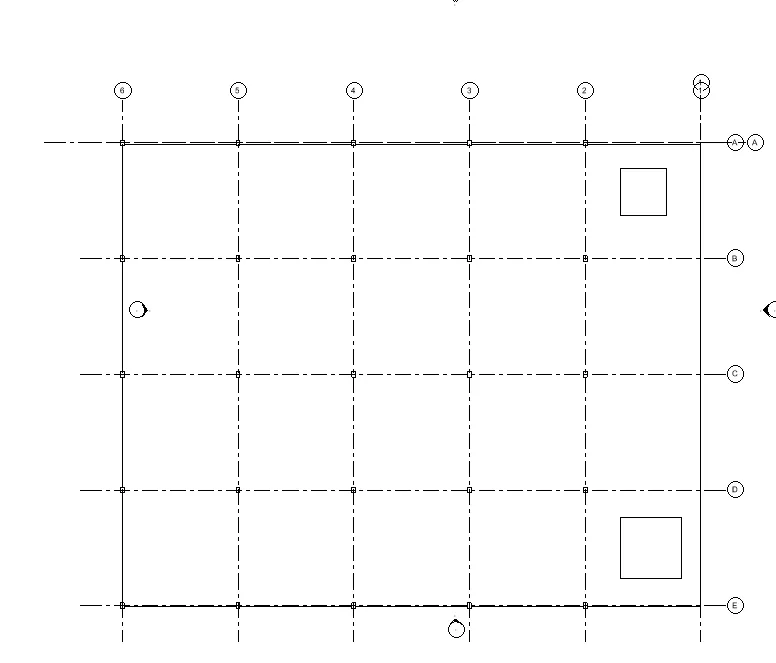
- Select the copy monitor command to copy the grids
- Go to visual graphics and select custom in annotation off the grids
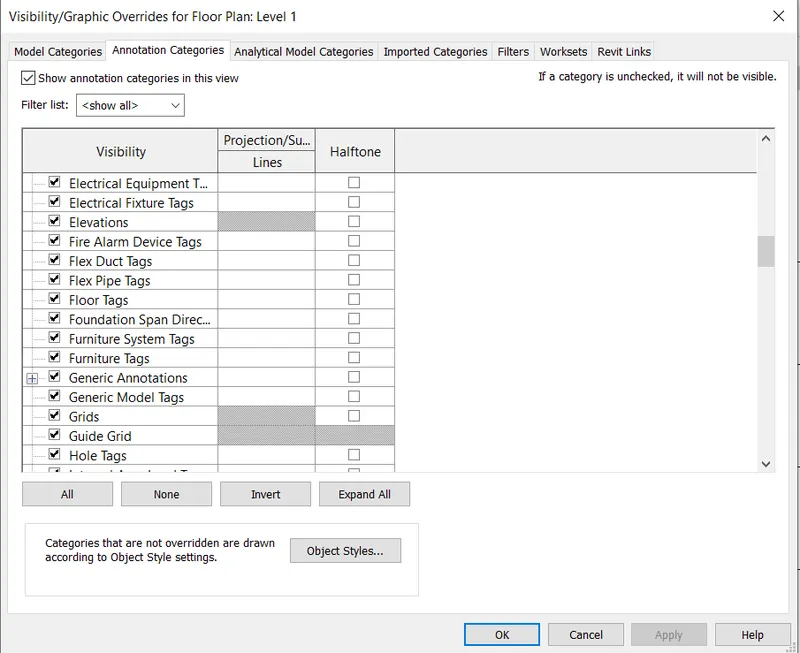
- Now we can only see architectural grids
- Go to elevation and do the same thing as we did for grids
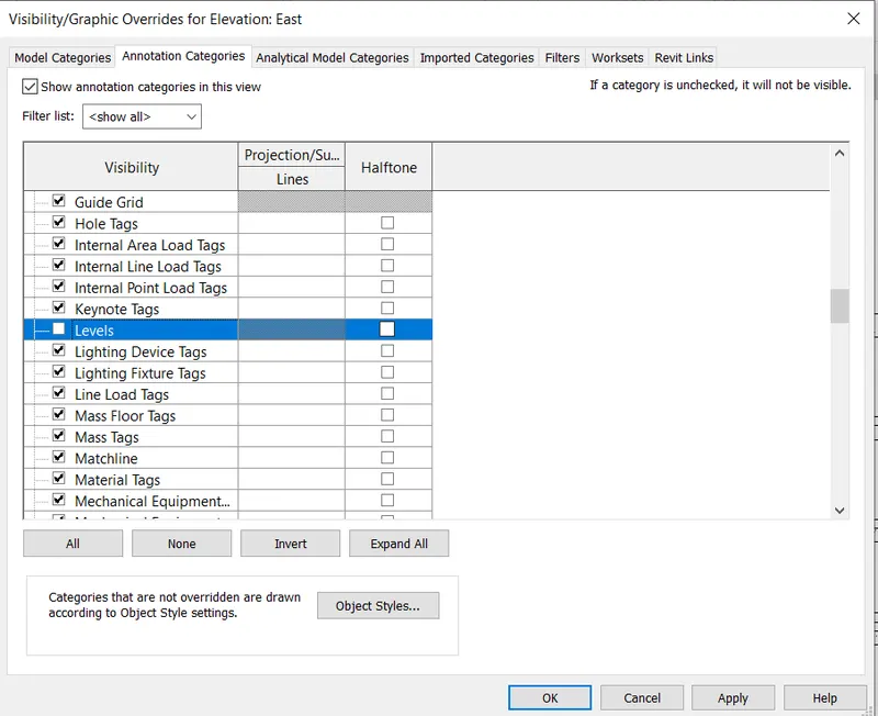
- Click on wall command to draw walls in ground floor
- Choose the top constraint as roof and go to 3D view
- Select the wall near lobby area to change it as glazed wall
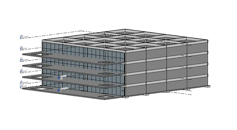
- Go to ground floor to draw partition walls for interior rooms
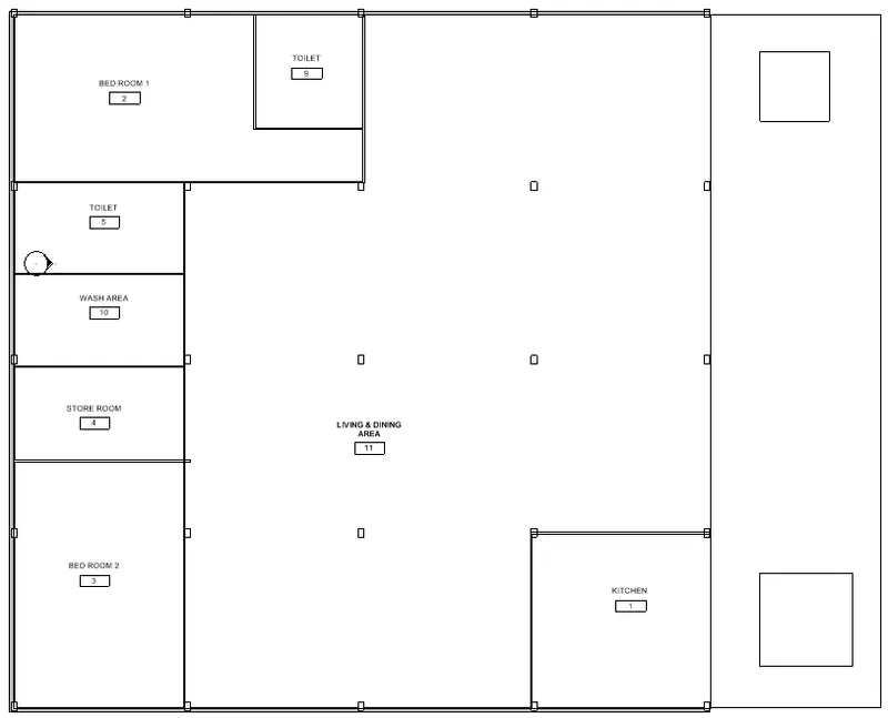
- Draw doors at required positions by choosing door command
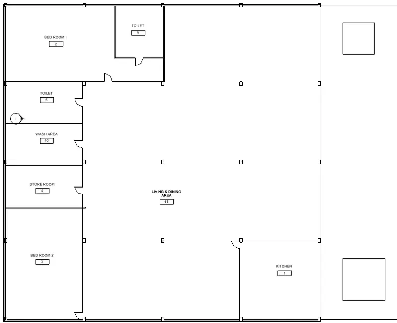
- Draw windows by selecting windows command at required locations
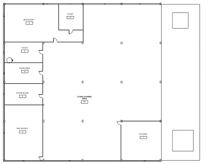
- Click on ceiling command and draw by selecting walls in ground floor
- Copy ceiling and paste it to all selected levels
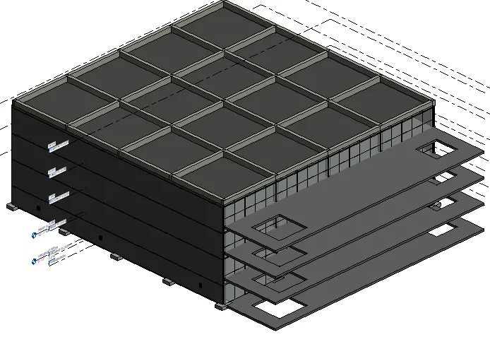
- Draw railing wherever required
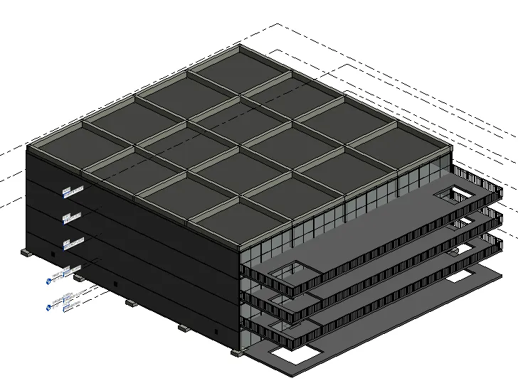
- Go to insert tab and click on load family command to load components such as chair, desk, sofa etc.
- Click on component command under architecture tab to place components at appropriiate locations
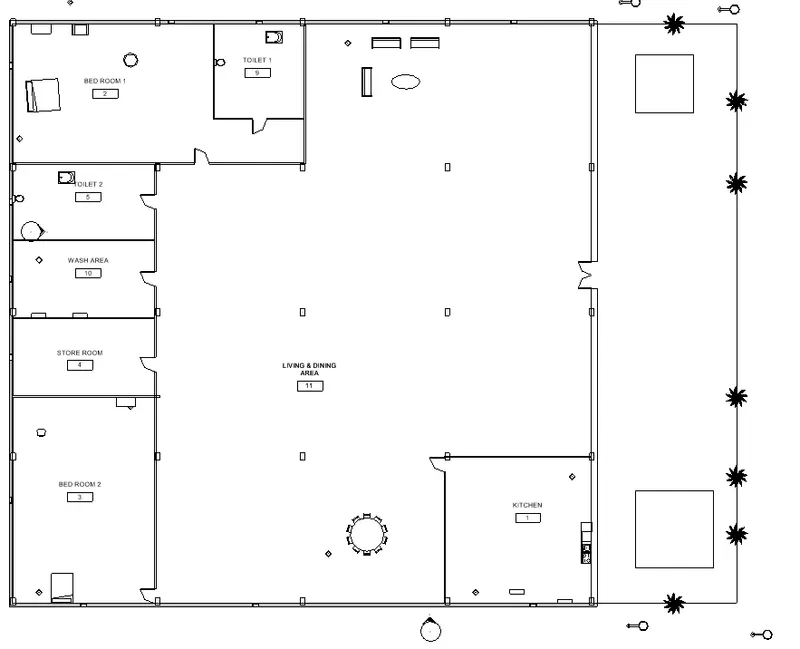
- Add roof to the building
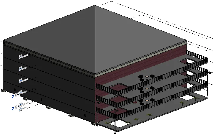
- Also add components like trees, plants in the outer area
RESULT : Using architectural model, few given components are added to the model
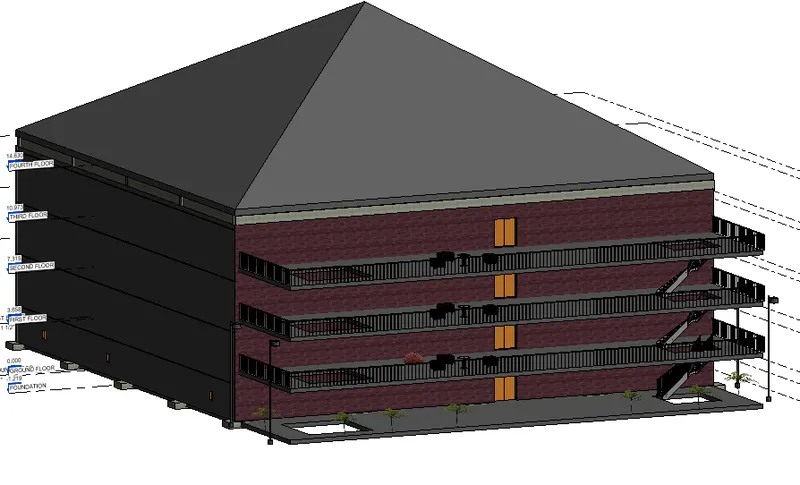
5) Provide set of drawings in architectural and structural models to list the following details with categories and appropriate sheet templates included
- Floor plans with annotations
- Elevations
- Sections
Ans.
AIM : To list the given details for the set of drawings in sheet templates
TOOLS USED :
- Sheets
- Project browser
- Section
PROCEDURE :
- Open revit and open project file
- Go to view tab, click on sheet command and load it from the family
- Drag floor plans and elevation views from project browser into sheets
- Rename sheets accordingly
- Go to view tab and click on section command to get sections
- Drag those section views also to the sheets and rename them and save the file
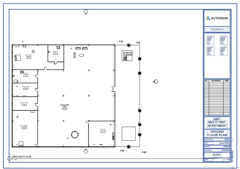
RESULT : Set of drawings are provided in architectural and structural models in sheet templates to list the given details
6) Using rendering settings, render images of 3D model produced and include the rendered images to the drawing sheets
- Rendering from interior rooms
- Rendering from out showing topographic features
- Rendering through structural framing
Ans.
AIM : To render images of 3D model and to include them into sheets
TOOLS USED :
- View
- Render
- Sheets
PROCEDURE :
- Open the project file in revit
- Open images of interior rooms and exterior look
- Go to view tab and click on render command
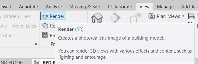
- Select the properties accordingly
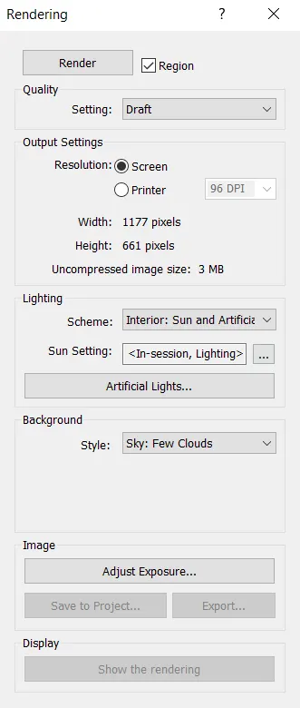
- Now load the sheet and drag the rendered images into the sheets
- Rename them accordingly
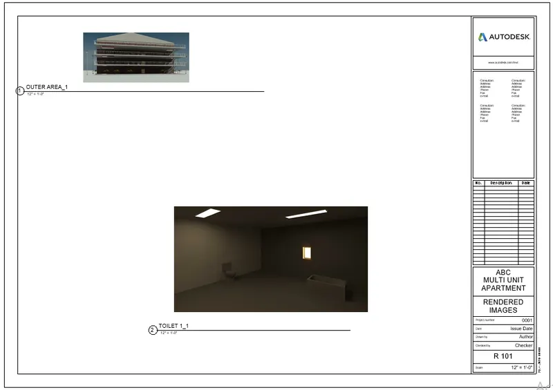
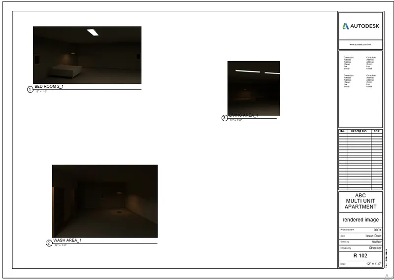
RESULT : Rendering of images is done by above procedure and can be included into drawing sheets
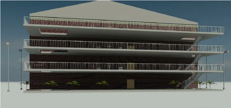
7) Print the set of drawing sheets and submit fom architecture and structure model
Ans.
AIM : To print set of drawings and to submit
TOOLS USED :
- Setup page
- Select the plotter
PROCEDURE :
- Go to view tab and select print command
- Adjust the page settings and print the drawing sheets
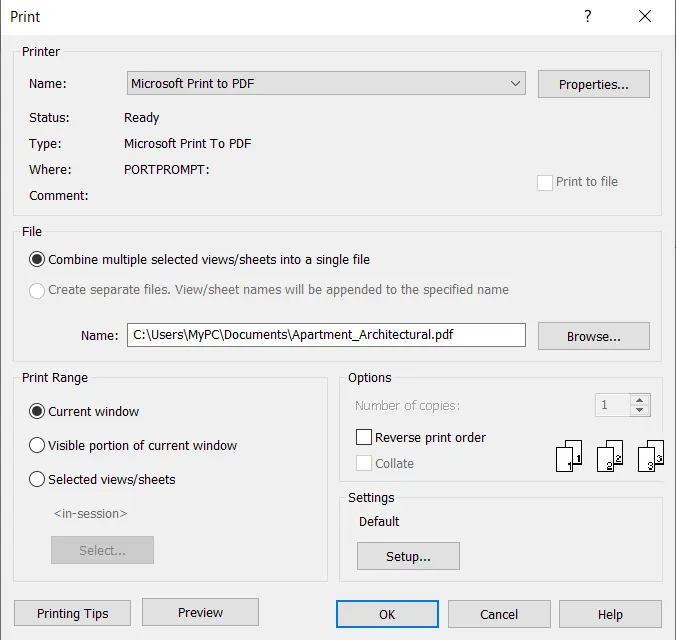
- Click ok to print the drawing sheets
RESULT :
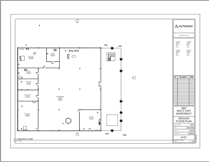
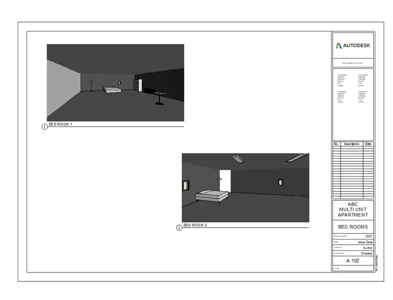
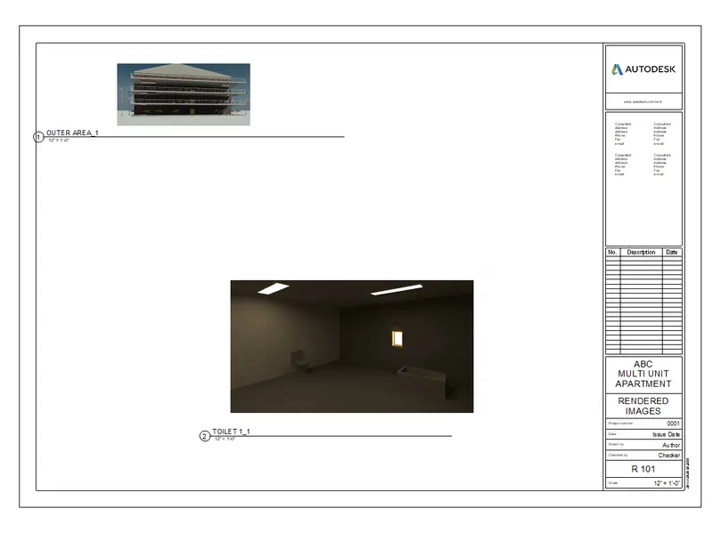
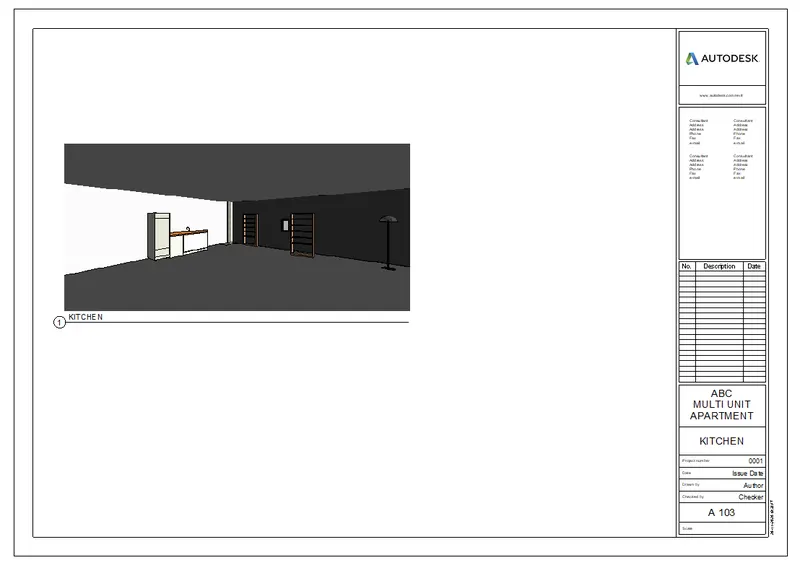
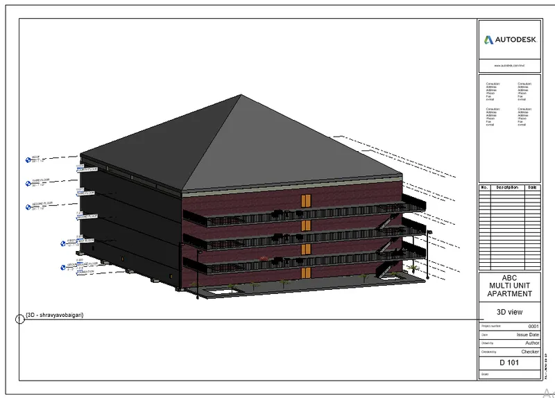
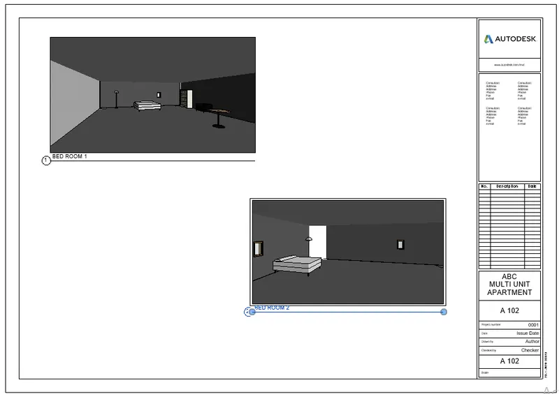
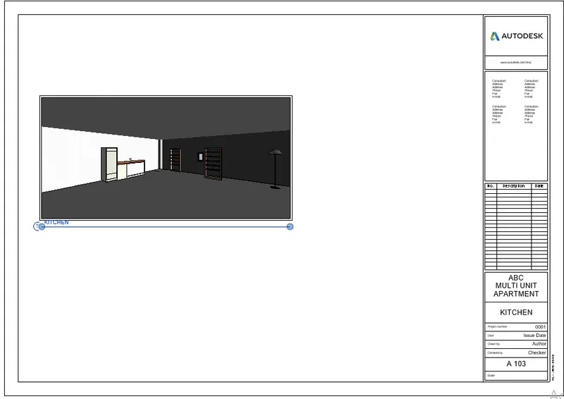
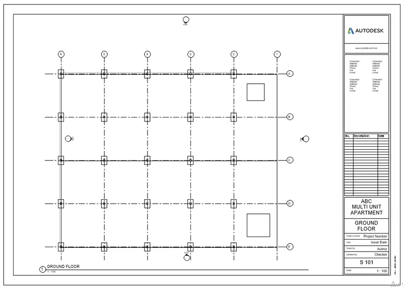
Following images are preview of the drawing sheets
Since, i am not having printer, i am inserting the images