REVIT_ Plan, 3D View & Structural Drawings_Project 2
1) Select the type of structure you want to build from one of the three below
a. Multi Unit Residential Apartment
b. Office Buildings
c. School
I want to build multi unit residential apartment from the given type of different structures
2) Assume reasonable assumptions for geographic and location details for your project modeling. Based on assumptions and type of structure selected identify the modeling requirements from NBC
ASSUMPTIONS FOR GEOGRAPHIC AND LOCATION DETAILS FOR MY PROJECT MODELLING WHICH I MADE ARE
- I want to design the residential appartment in plan area where a medium size population is located
- Road width infront of my appartment is 60'
THE MODELLING REQUIREMENTS FOR MY APPARTMENT AS PER NBC ARE
- Height limit as per FAR calculation as per NBC TABLE
- Fire and safety according to NBC TABLE
- Min width and length of rooms area according to NBC
3) Using the structural model, include the following components based on the type of structure selected
a. Foundation – Isolated / Wall/Matt Foundation
b. Columns
c. Beams Connected to Columns
d. Roof Framing/ Truss
e. Floor / Decks
f. Floor Openings for Elevators and Stairs
AIM:TO INCLUDE THE FOLLOWING COMPONENTS TO THE RESIDENTIAL APPARTMENT MODEL
TOOLS AND COMMANDS USED:
- Columns
- collaborate
- Foundation
- Floor
- stairs
PROCEDURE:
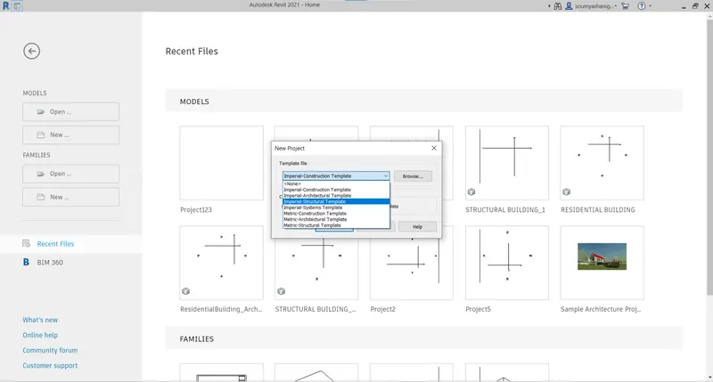
STEP-1:Open the revit file and open structural template
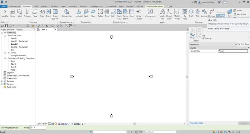
STEP-2:Open structural tab and choose grids option
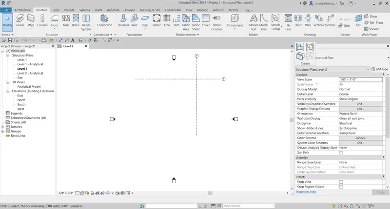
STEP-3:draw lonigitudinal and traverse grids and name them as required
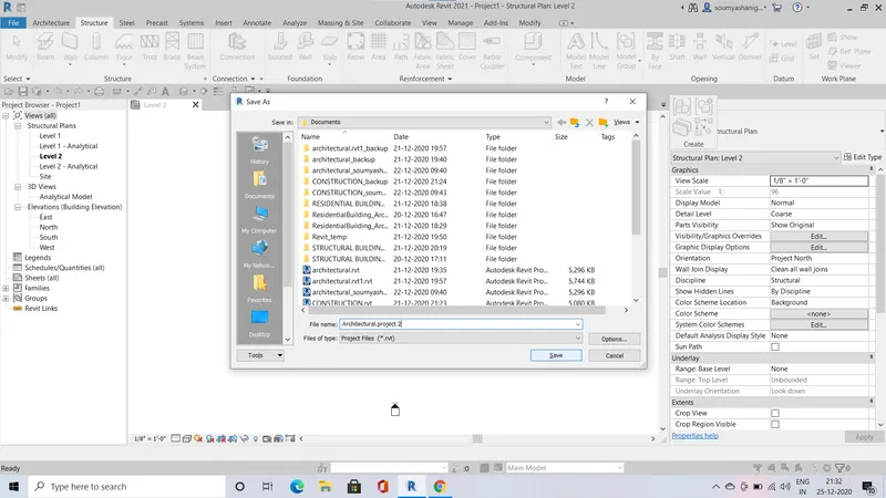
STEP-4:save the file by choosing save option and name them as required type
STEP-5:ChOOSE COLLOBORATE TAB tab and click colloborate tab
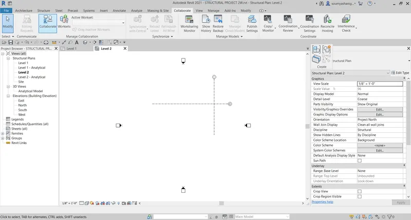
STEP-6:a dialog box appears then click ok and click colloborate tab and select synchronize with central then click ok (this means we are making file as central model)
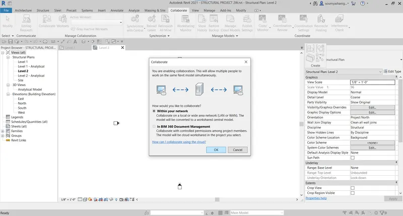
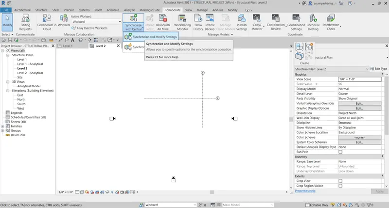
Click ok
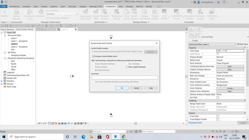
STEP-7:Now open architectural template and open architectural tab and choose grids
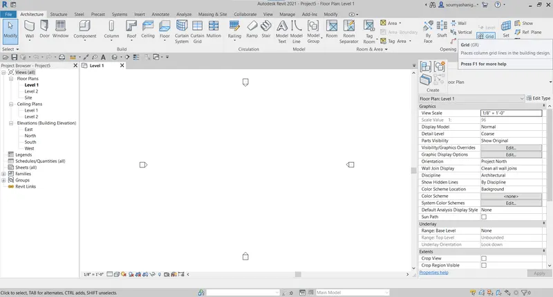
STEP-8:draw traverse and longitudinal grids and name them if required
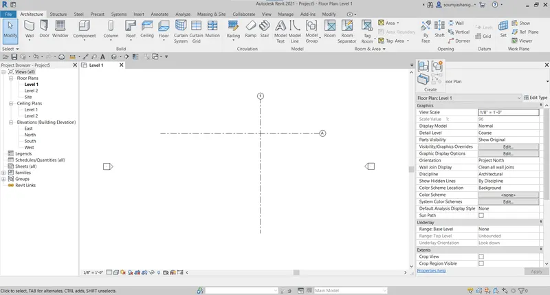
STEP-9:Save the file with appropriate name
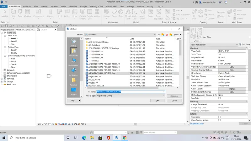
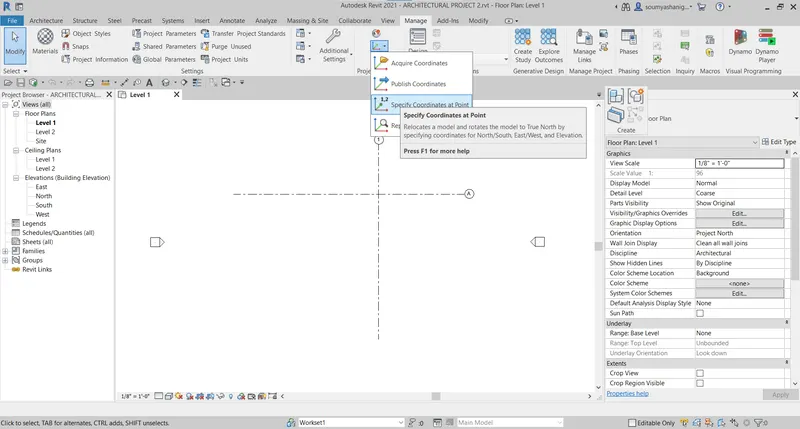
click manage tab and select specify coordnitaes and make each grid as 0' point (both longitudinal and horizontal)
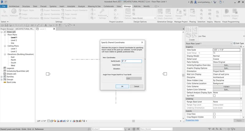
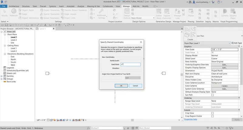
STEP-10:open Colloborate tab and click colloborate option then a dialog box appears then click ok
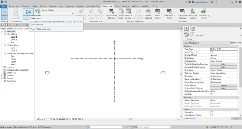
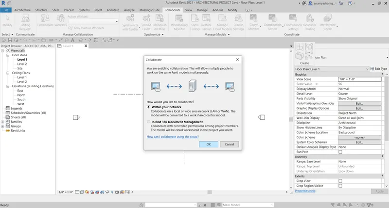
STEP-11:now click colloborate tab and select synchronize with central and click ok when a dialog box appears
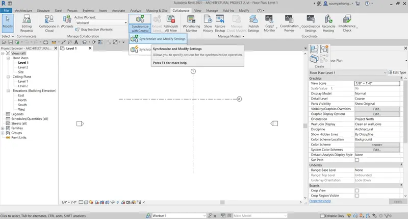
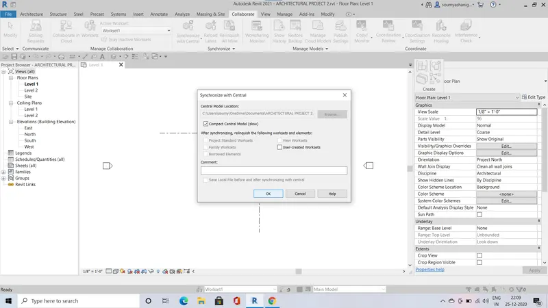
STEP-12:Now open saved architectural model and choose manage link from manage tab
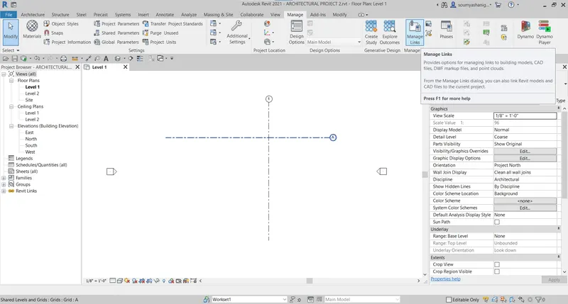
STEP-13:Adialog box appears then click on add then it takes to projects which made by oneself then open required project and click ok
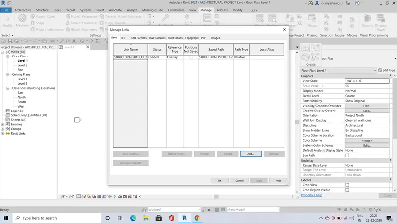
STEP-14:Now both template are visible in one tempalte
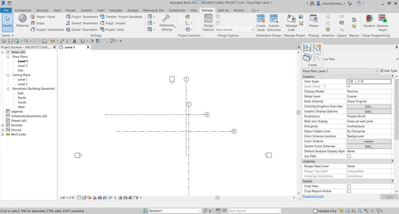
STEP-15:Now select manage tab and chose specify coordinates
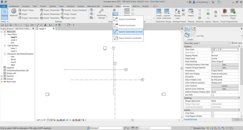
STEP-16:now select a grid and make them as 0'0'' and do the same process to all grids and make them in one file
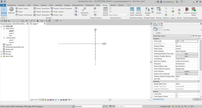
STEP-17:save the file
STEP-18:Now open the structural template and select grids
STEP-19:draw grids at equal interavals in both longitudinaly and transversely
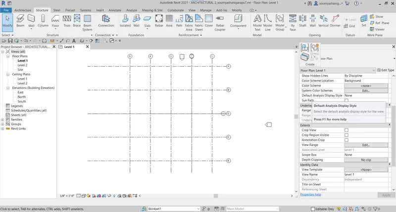 CLICK STR
STEP-20:Click structural tab and select column
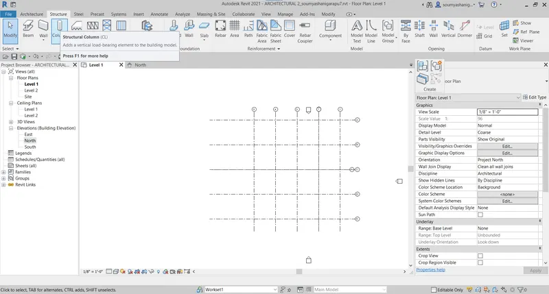
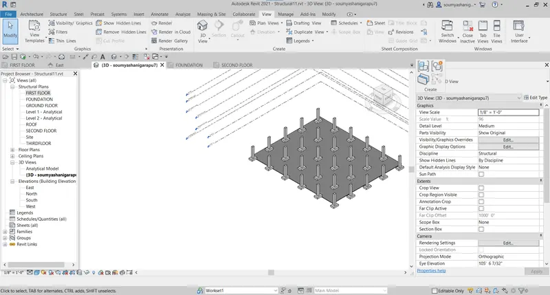
STEP-21:select structural tab and choose columns and footings and place them in appropriate location
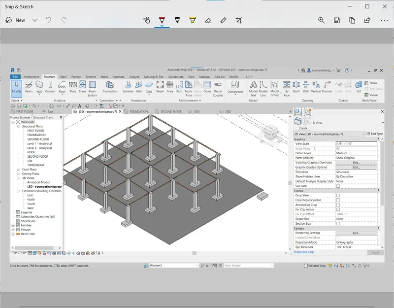
STEP-22:Now select structural tab and select beams ana place in appropraite place
STEP-23:Select entire layout and attach to the different levels by selecting copy icon
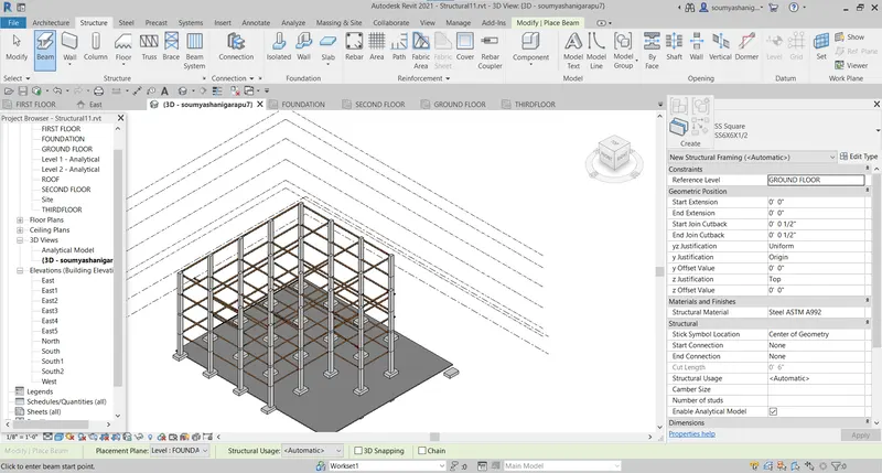
STEP-24:Select slab and frst select the layout then click right then the slab is obtained to first floor then now attach to diffrenet levels
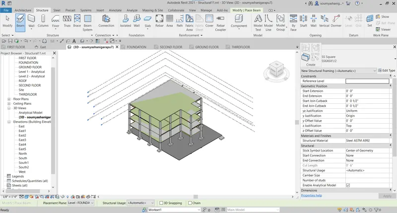
RESULT:All the structural components like beams footing,slab are palced successfully in the model
4) Using the architectural model, include the following components based on the type of structure selected
a. Wall Layout with appropriate material and finishing
b. Exterior façade with fancy finish
c. Interior partition walls to size rooms
d. Components to add details to room ( Desk, Chair, Lighting, Plumbing fixtures)
e. Add components such as stairs Elevators
f. Have at-least one side of building with curtain walls and glass panels
g. Include interior and exterior lighting fixtures
h. Place proper topographic components from outside ( Trees, Parking, Plants) to add details to the model
AIM:TO INCLUDE FEW COMPONENTS IN ARCHITECTURAL MODEL
TOOLS AND COMMANDS USED:
- Doors
- Architectural tab
- Rooms
- Stairs
- Ligthing
PROCEDURE:
STEP-1:Open revit file and select architectural model
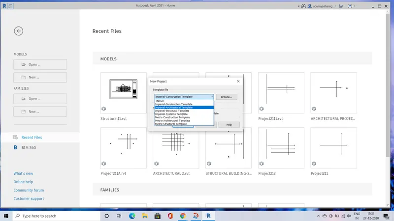
STEP-2:Now select architectural tab and choose grids
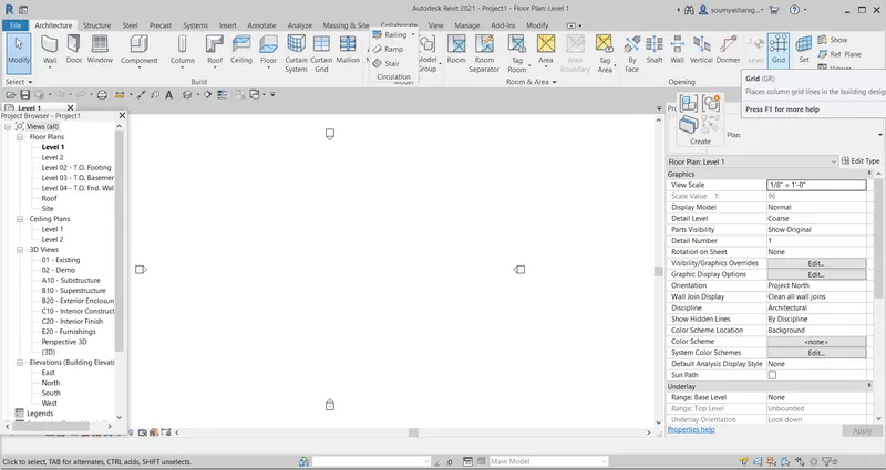
STEP-3:now draw lonitudinal and traverse grids with equal intervals
STEP-4:name them with appropriate names
STEP-5:Now select the wall tab from architectural tab
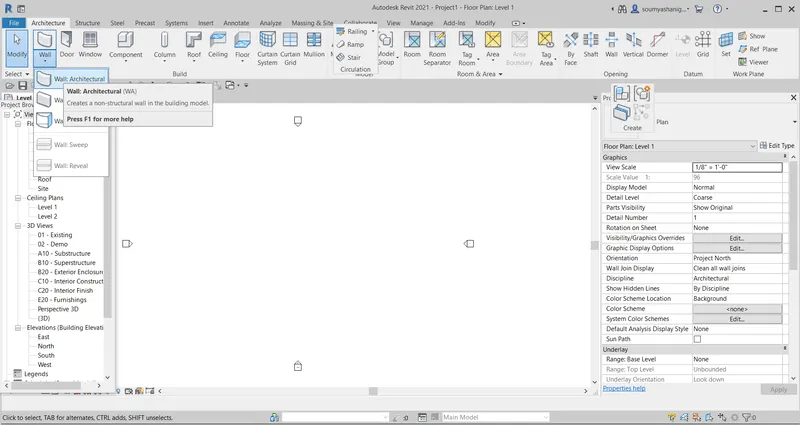
STEP-6:Now draw the rooms with conventient sizeBy choosing interior partition wall
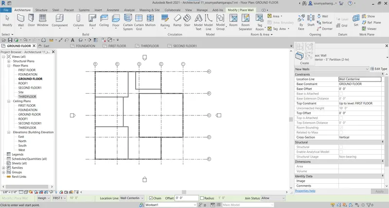
STEP-7:Now select room tag from architectural tab and name the room by this tag
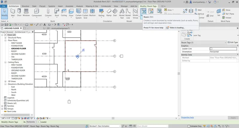
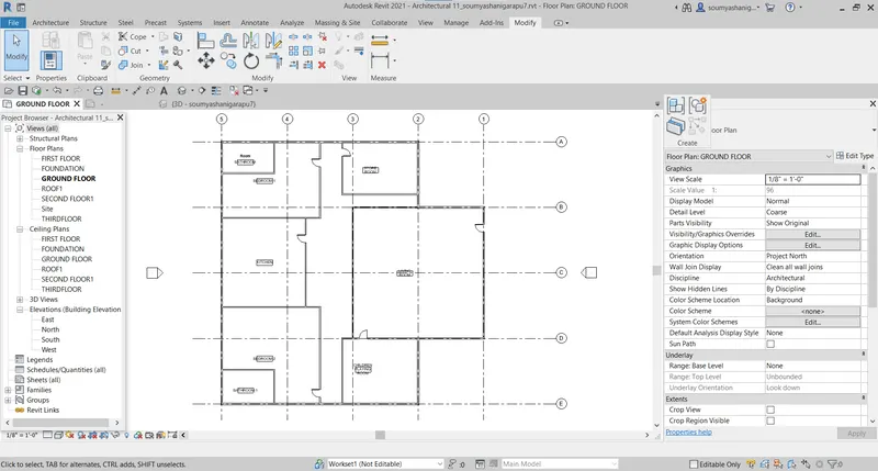
STEP-8:Now select floor tab from architectural tab
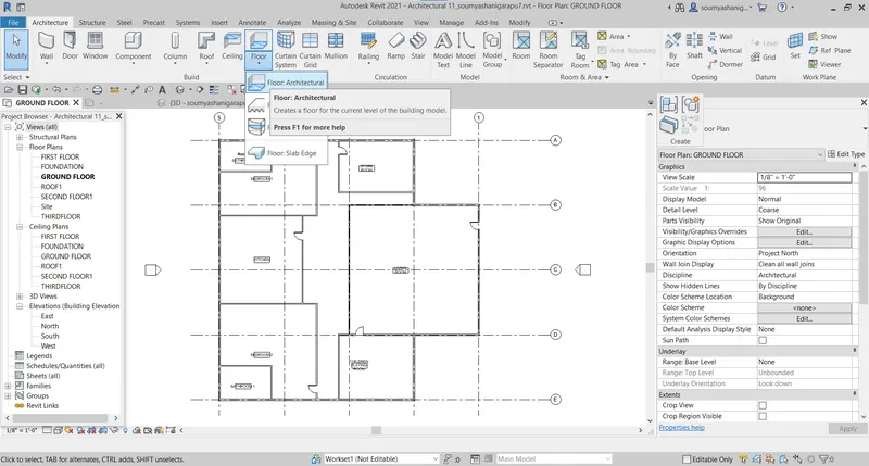
STEP-9:Now select the rectangle box icon and select the wanted layout
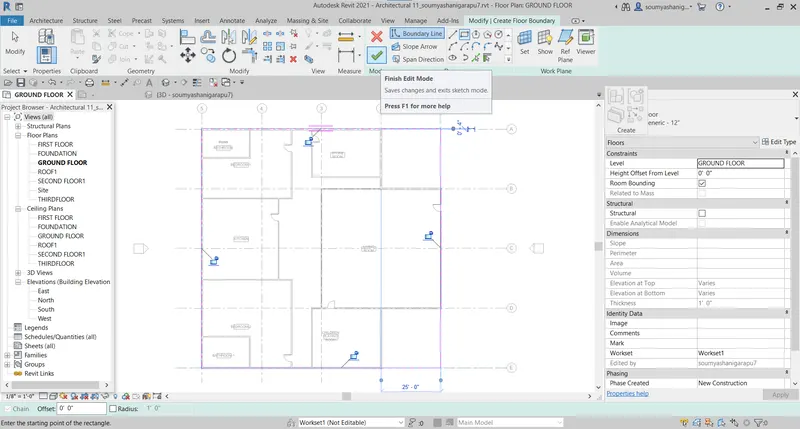
STEP-11: Click right mark then the entire layout will be selected
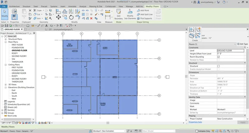
STEP-12:Now select floor layout and select the required type of floor materials by choosing in properties browser
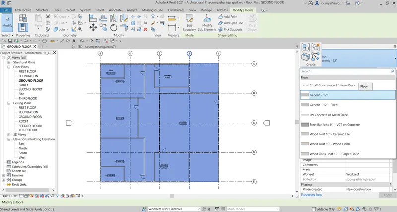
STEP-13:Now select one material and one can edit the thickness material etc by choosing edit option
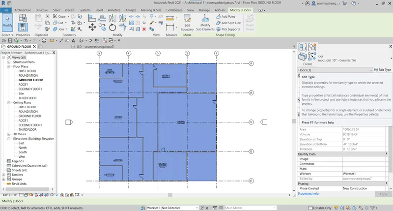
STEP-14:A dialog box apperas and change the thickness if required and click ok

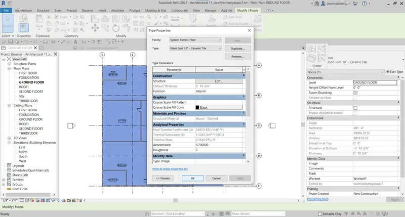
STEP-15:one can view the floor material in 3d view
click view option and and select 3d view
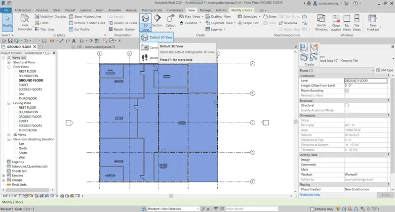
3D VIEW
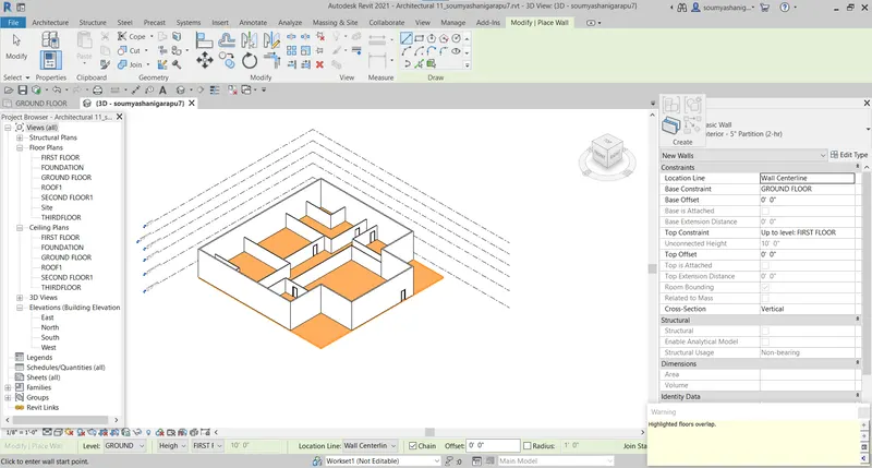
STEP-16:Now to change the material of wall select one wall in 3d view
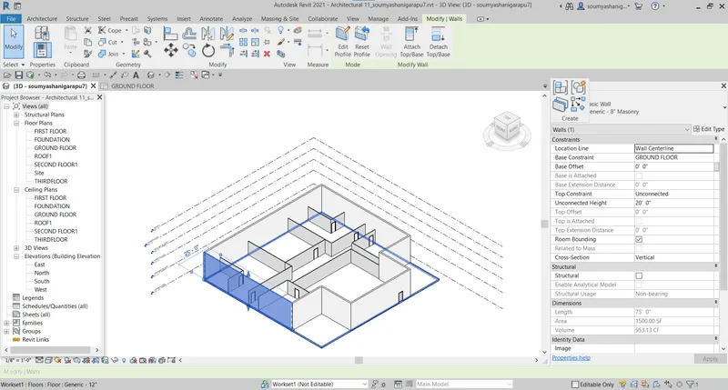
STEP-17:Now select the required material from propeties browser
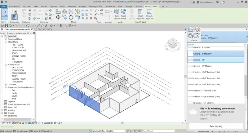
STEP-18:Now select ok option then do the same thing for other walls also then the structure changes to like this
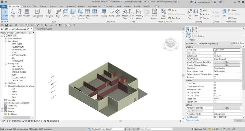
STEP-19:now the height of interior walls are not at same height with outer walls so to make that select one interior wall
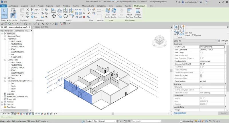
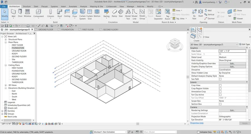
STEP-20:Select top constraint option from properties browser and make up to required level
STEP-21:Do to all walls
STEP-22:Place components to the model by selecting place a component from architectural tab
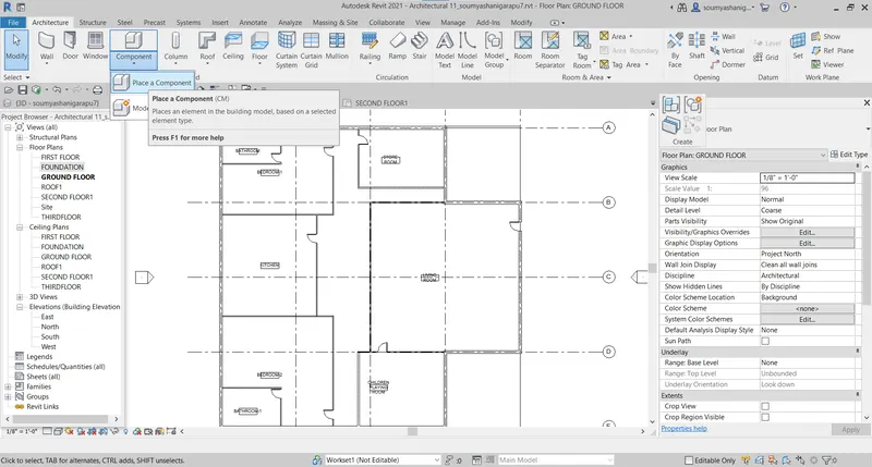
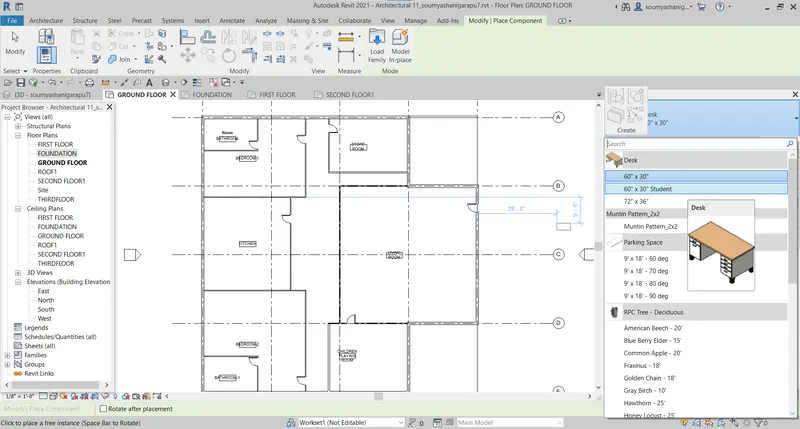
STEP-23:Place a desk in required place by selecting it from properties browser
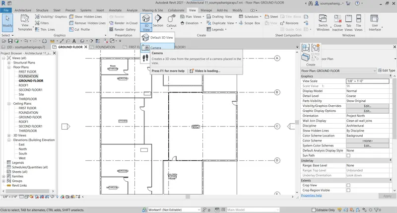
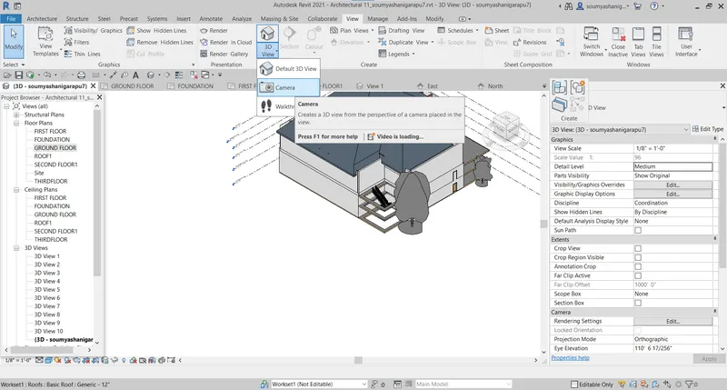
STEP-24:To view desk view in plan select view and select camera
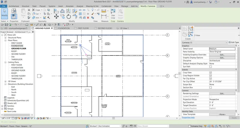
STEP-25:place camera in appropriate place and make the rays to pass in proper items to view the desk
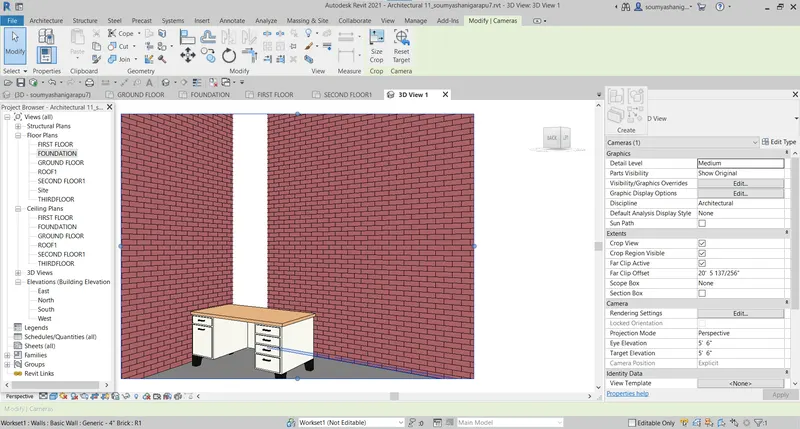
STEP-26:if no elements were found then select load family from insert tab
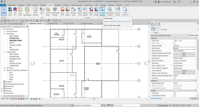
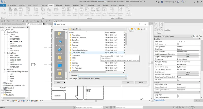
STEP-27:a group of components will be appear then select the require element and click open then the component will be in properties browser
STEP-28:Now place the components like dinning table sofas etc in the model by using the above mentioned process
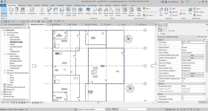
STEP-29:Now select the layout and copy the elemnts and select paste to alligned levels
STEP-30:paste it to all three levels
STEP-31:Now select roof from architectural tab then a dialog box appears click upto roof
STEP-32:Then select walls and place roof
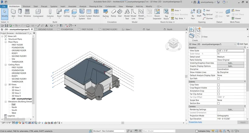
STEP-33:now add stairs so select stairs from architectural tab
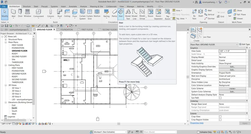
STEP-34:A group of optionns visible select any one option and palce stairs in the layout
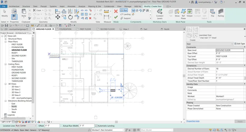
STEP-35: copy stairs to different levels
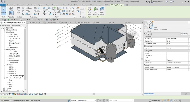
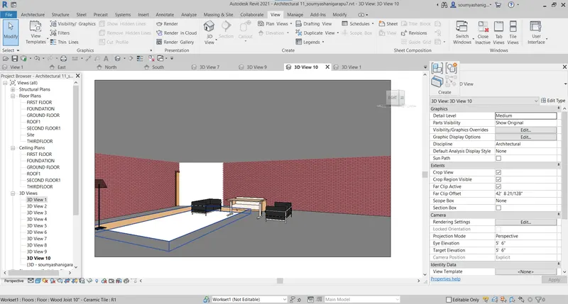
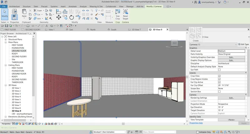
STEP-36:View the all components by using camera view by choosing option from view tab
LIVING ROOM:
KITCHEN:
BEDROOM:
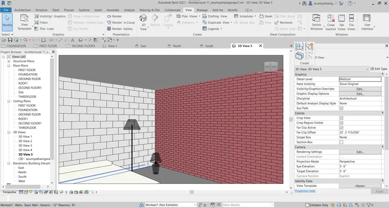
RESULT:ALL THE COMPONENTS LIKE SOFAS LIGTHING PLUMBING ,FLOORS ,ETC TO THE MODEL ARE SUCCESSFULLY ADDED TO THE MODEL
5) Provide set of drawings in architectural and structural model to list the following details with categories and appropriate sheet templates included
a. Floor Plans with Annotations
b. Elevations
c. Sections
AIM:TO PROVIDE SET OF DRAWINGS IN ARCHITECTURAL AND STRUCTURAL MODEL TO LIST FEW DETAILS WITH CATEGORIES AND APPROPRIATE SHEET
TOOLS AND COMMANDS USED:
- Sheet
- view
- elevation
- floor plan
- section
PROCEDURE:
OPEN THE PREVIOUSLY CREATED LAYOUT
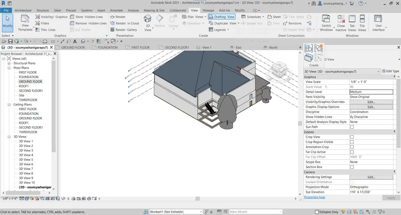
STEP-1:GO TO VIEW TAB AND SELECT SHEET TOOL
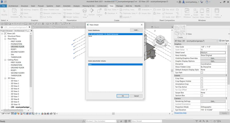
STEP-2:Then a dialog box appears select required type of sheet click ok
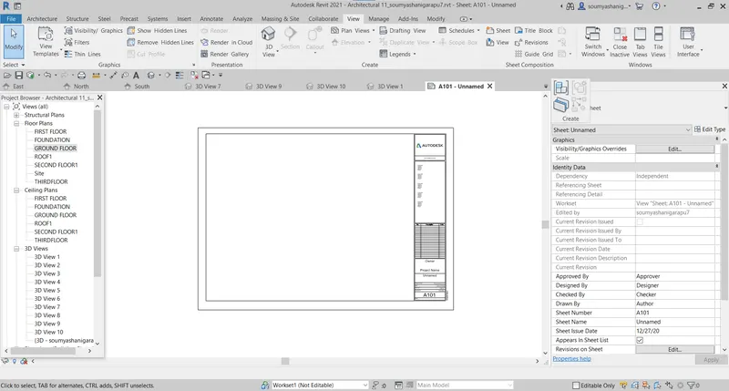
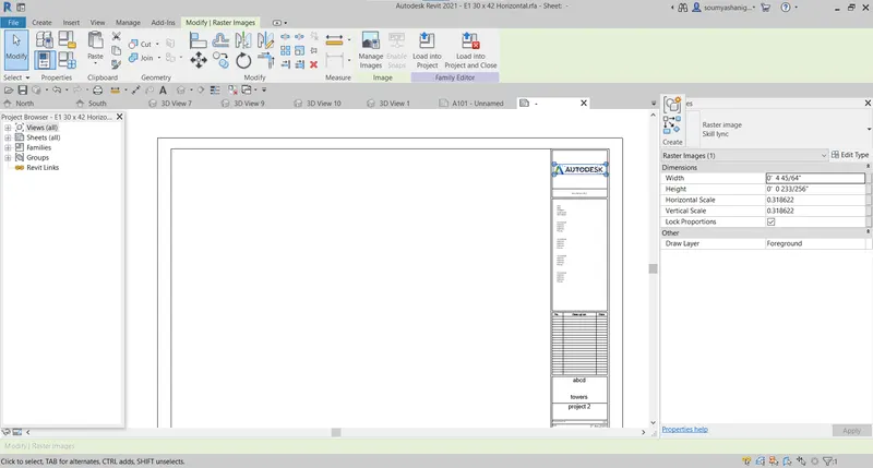
STEP-3:Sheet appears on the screen then make required changes on the sheet by double clicking at particular name and change the name to appropriate name
STEP-4:go to view tab and select view tab
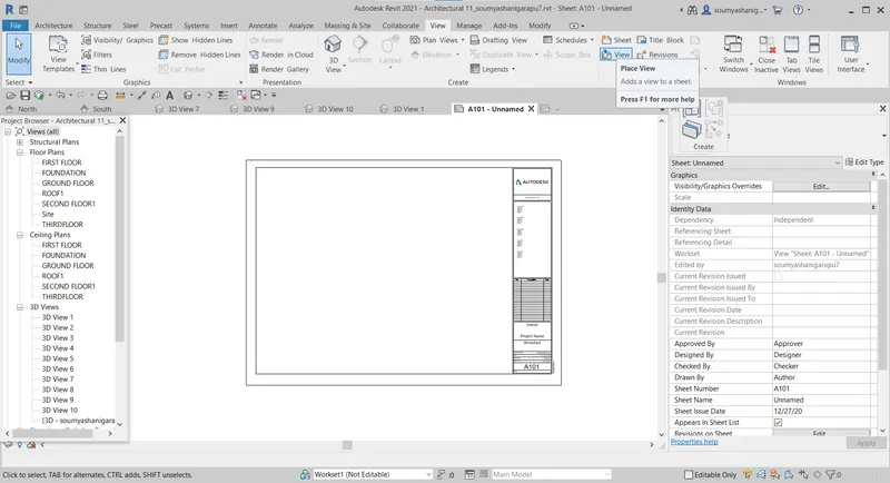
STEP-5:A dialog box appears then choose required view to be placed in the sheet
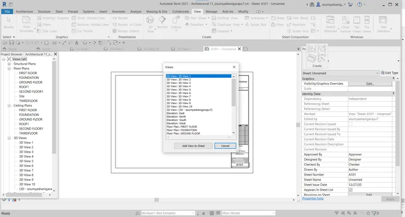
STEP-6:click on add view to sheet select east and click on add to sheet
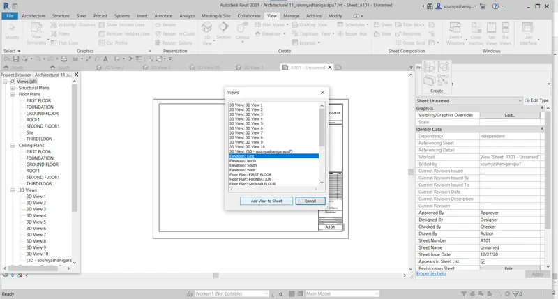
STEP-7:East view will be placed on the sheet
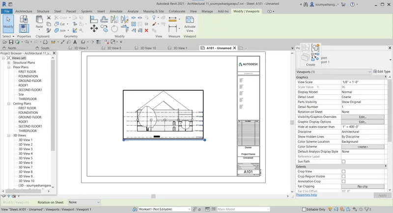
STEP-8:Do the same process to all views by selecting and adding to sheet
WEST VIEW
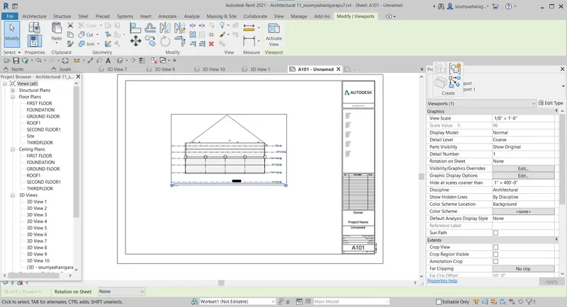
SOUTH VIEW:
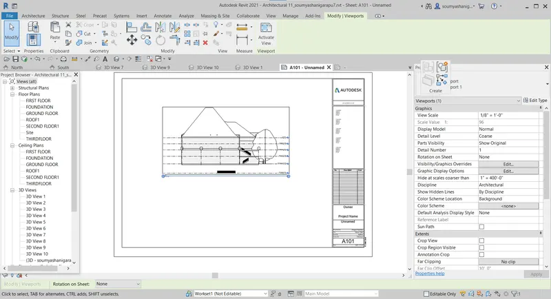
NORTH VIEW:
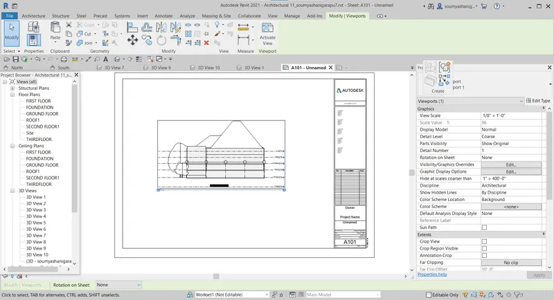
FIRST FLOOR
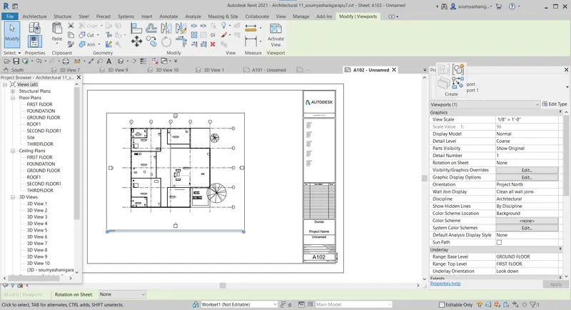
SECOND FLOOR STRUCTURAL VIEW
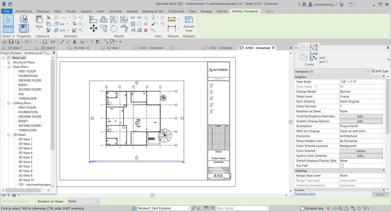
STRUCTURAL AND ARCHITECTURAL VIEW:
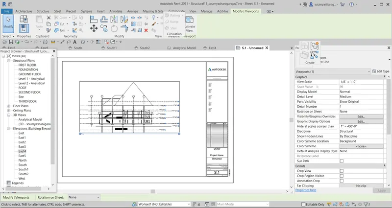
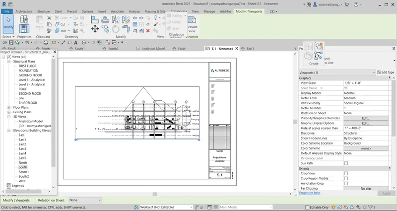
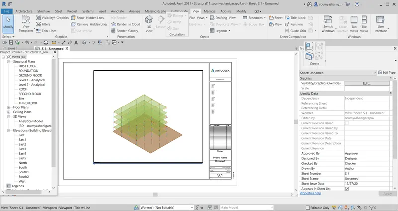
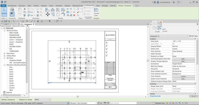
EAST STRUCTURAL VIEW:
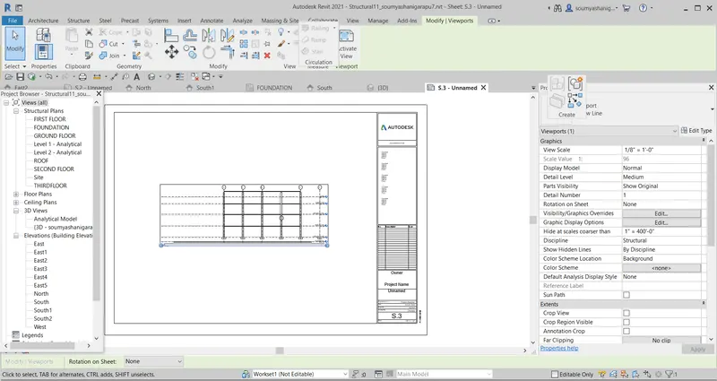
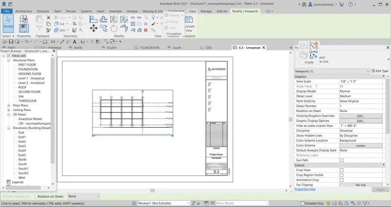
RESULT:ALL views section view etc OF STRUCTURAL AND architectural model are placed in sheet properly by the help of view tab
6) Using the Rendering settings, Render images of 3D model produced and include the rendered images to the drawing sheets
a. Rendering from interior rooms
b. Rendering from out showing topographic features
c. Rendering through structural framing
AIM:TO TENDER THE IAMGES WHICH WERE CAPTURE BY THE CAMERA VIEW FOR EXAMPLE LIKE THE INTERIOR ROOMS TOPOGRAPHIC VIEWS AND STRUCTURAL FRAMING
TOOLS AND COMMANDS USED:
- Render
- Region
- Style
- Scheme
- Sheet
PROCEDURE:
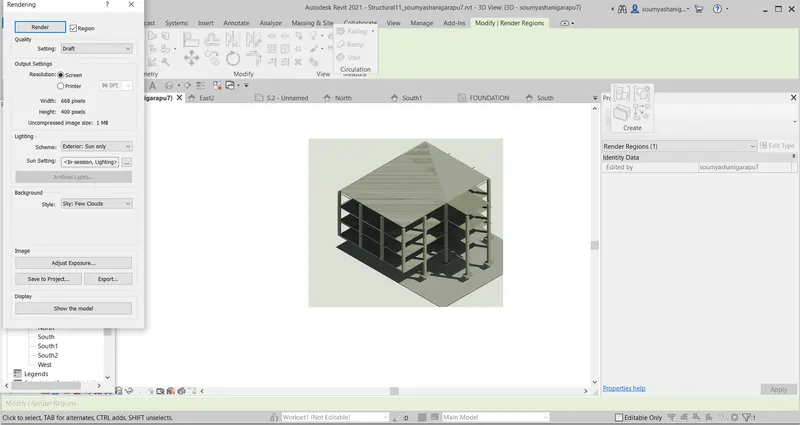
STEP-1: Open the previously created file and view the file in 3D VIEW
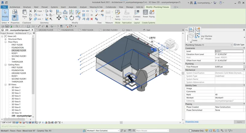
STEP-2:Go to view menu and click on render option
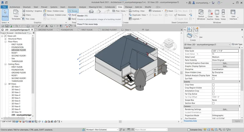
STEP-3:A dialog box appears
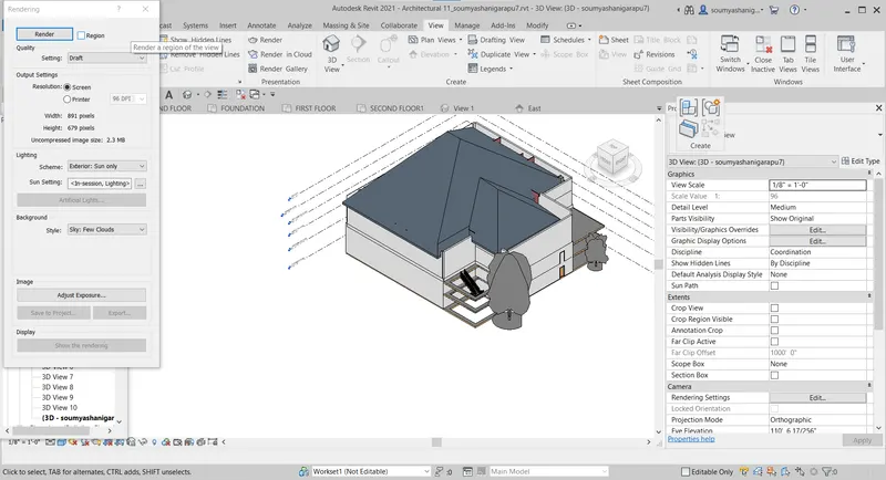
STEP-4:Now select any camera 3d view
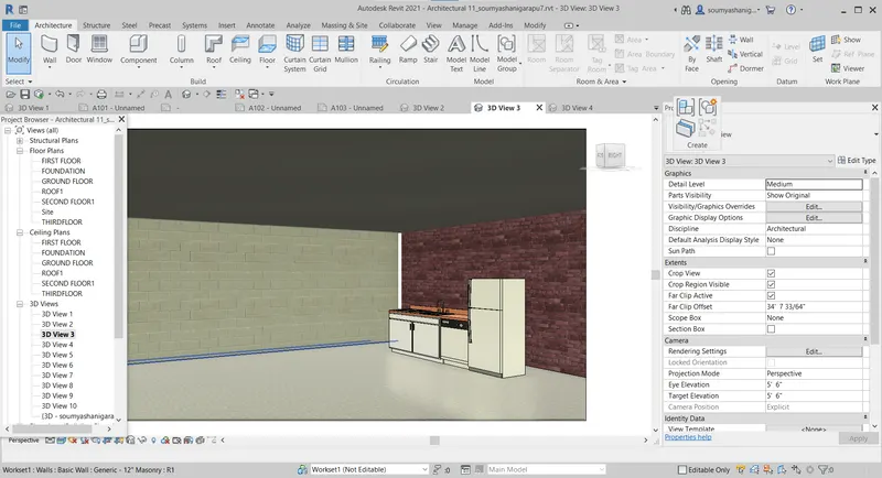
STEP-5:Now select render option and make necessary changes to that render dialog box
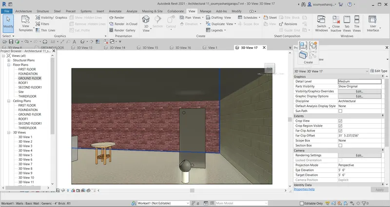
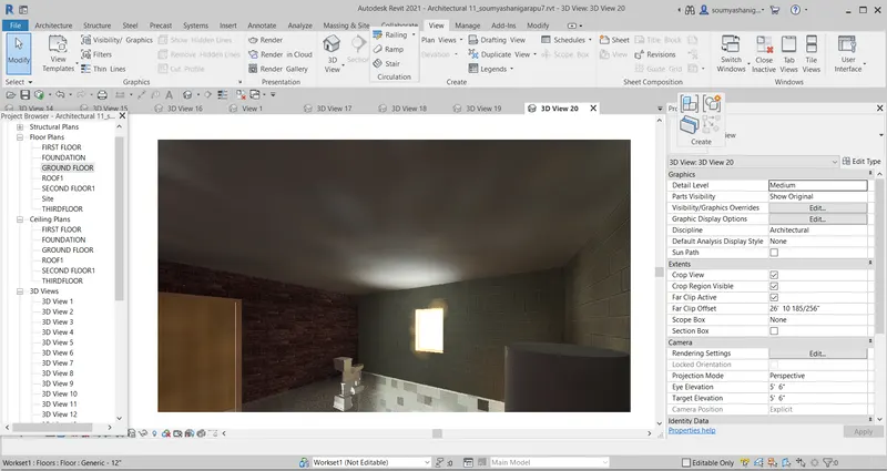
KITCHEN VIEW:
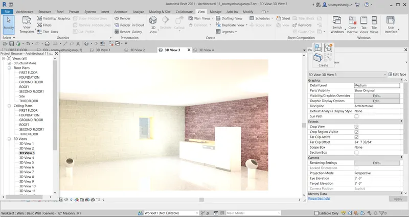
BEDROOM:
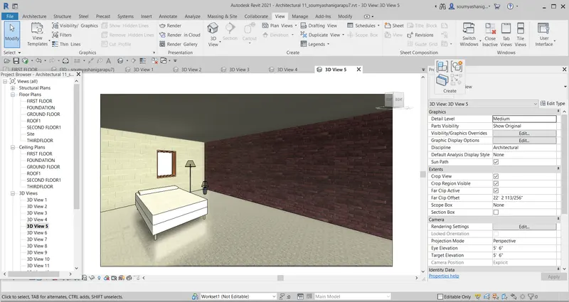
KITCHEN:
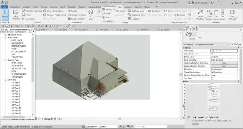
RESULT:
REBNDERING IMAGES OF STRUCTURAL AND ARCHITECTURAL WERE SUCCESSFULLY ADDED TO DRAWING SHEETS AND ONE CAN EDIT THE PROJECT TO REALISTIC VIEW WITH THE HELP OF RENDER IMAGE
7) Print the set of drawing sheets created and submit the drawings from architecture and structure modeL
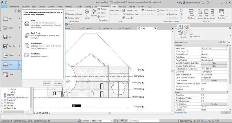
AIM:TO PRINT THE SET OF DRAWING SHEETS CREATED AND SUBMIT THE DRAWINGS FROM ARCHITECTURAL AND STRUCTURAL MODEL
TOOLS AND COMMANDS USED:
- FILE
- SETUP PAGE
- PLOTTER
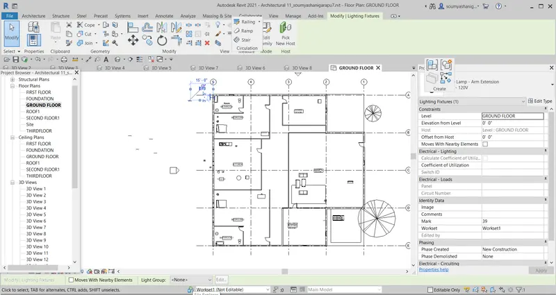
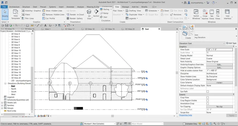
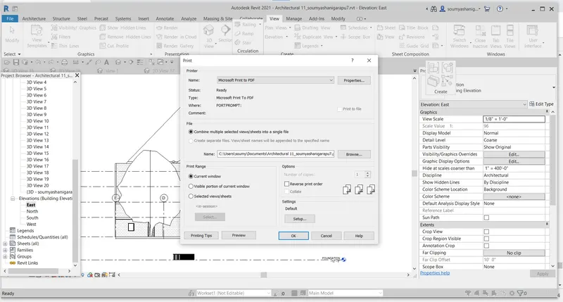
TEP-7:East view will be placed on the sheet
WEST VIEW
SOUTH VIEW:
NORTH VIEW:
FIRST FLOOR
SECOND FLOOR STRUCTURAL VIEW:
STRUCTURAL:
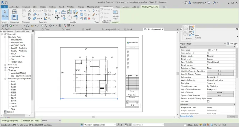
STERUCTURAL AND ARCHITECTURAL VIEW:
RESULT:ALL VIEWS ARE PLACED IN THE SHEET BUT IT IS NOT PRINTED BECAUSE OF UNAVAILABILITY OF PRINTER