REVIT_ Plan, 3D View & Structural Drawings_Project 2
1) Select the type of structure you want to build from one of the three below
a. Multi Unit Residential Apartment
b. Office Buildings
c. School
ANS: I want to build a Multi unit Residential apartment from the above structures
2) Assume reasonable assumptions for geographic and location details for your project modeling. Based on assumptions and type of structure selected identify the modeling requirements from NBC
sol: assumptions made for geographical and loacation details of my project and Modelling requirements from NBC :
- my project is in residential area
- road width infront of appartment is 60'
- My project is in plain area
- area measures should be under NBC rules
- the height of building should not exceed 1.5 times the width of the road width
- fire safety is also provided as per NBC
3) Using the structural model, include the following components based on the type of structure selected
a. Foundation – Isolated / Wall/Matt Foundation
b. Columns
c. Beams Connected to Columns
d. Roof Framing/ Truss
e. Floor / Decks
f. Floor Openings for Elevators and Stairs
AIM: To include the compnents based on multi unit residential apartment
TOOLS USED:
STRUCTURAL>
- GRIDS
- LEVELS
- COLUMNS
- FOUNDATION
- BEAMS
- FLOOR
- SHAFTS
PROCEDURE:
- open a structural model created in week 6 which has specify cordinates a s 0'
- save the file with appropriate name
STEP-1:
- Go to elevation and click on any of them (east)
- select the levels in strcurtural model
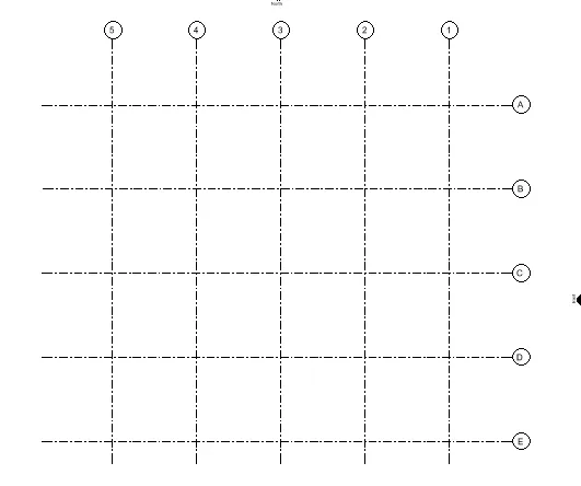
- select grids in structural tab
- draw grids longitudinally and horizontally and name them accordingly
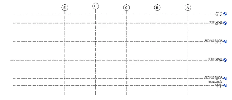
- draw required levels for the building with 12' offset and foundation of 4'6''
- name them as ground floor,foundation,first etc.,
STEP-2:
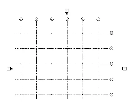
- under structural tab click on columns
- place the coloumns as required
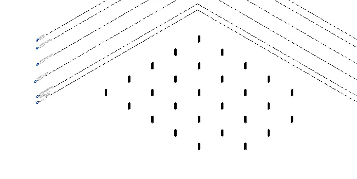
- click on isolated foundations
- place them in foundation level
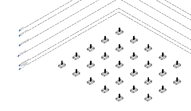
- select at columns loacted at top right corner
- click on beams and add the beams to the columns
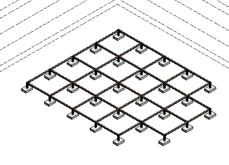
STEP-3
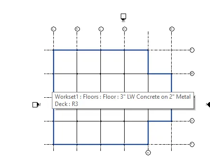
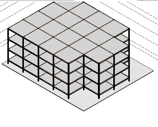
- select the whole plan view created and copy it
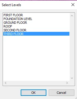
- paste it with the help of alligned to selcted levels to different levels
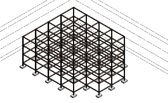
- click on floor command and draw floor to ground floor
- copy the floor from ground floor and add it to other levels
STEP-4:
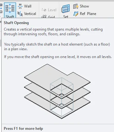
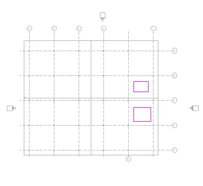
- Select the shaft command
- add it in the required place
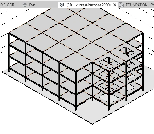
RESULT:
- hence, the structural model of residential unit appartment has been created and the folowing components are added
4) Using the architectural model, include the following components based on the type of structure selected
a. Wall Layout with appropriate material and finishing
b. Exterior façade with fancy finish
c. Interior partition walls to size rooms
d. Components to add details to room ( Desk, Chair, Lighting, Plumbing fixtures)
e. Add components such as stairs Elevators
f. Have at-least one side of building with curtain walls and glass panels
g. Include interior and exterior lighting fixtures
h. Place proper topographic components from outside ( Trees, Parking, Plants) to add details to the model
AIM: to include some components in residential uit appartment in architectural model
TOOLS USED:
ARCHITECTURAL>>
- COPY MONITER
- WALL
- PARTITION WALLLS
- LOAD FAMILY
- ROOF
- CEILING
- STAIRCASE
- RAILINGS
PROCEDURE:
- Open the architectural file that has been created in week 6 in which architectural and structural are combined
- select copy moniter and copy all the grids from structural fie
STEP-1:
- go to elevation click on east elivation view
- click on levels and add levels as required
STEP-2:
- clIck on wallls under architectural tab
- draw the plan as required with proper dimensions
- add inetrior partion wallls to size rooms
- add components from ;oad family
- ex:chair,beds.kitchen tools,lightning,plumbing,fixtures etc.,
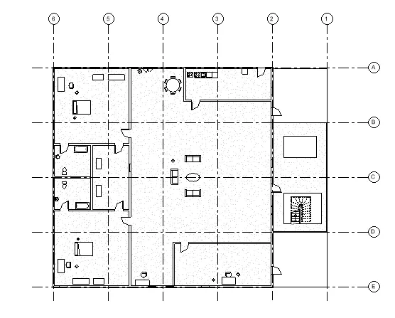
- add the exterior lighting ,planting ,parking etc., to make it more realistic
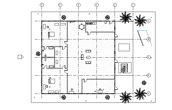
- one side of the building wall is made by glass
- railings are added from architectural tab
- staircase,trees,components are added as mentioned.
RESULT:
hence, residential unit building is added with the following mentioned components.
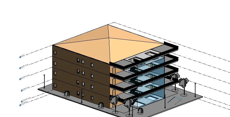
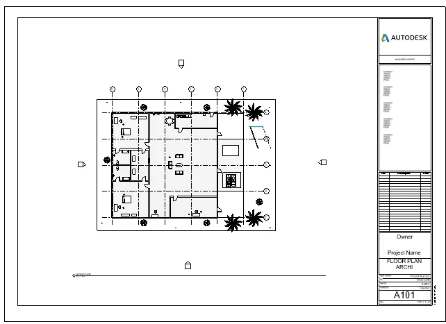
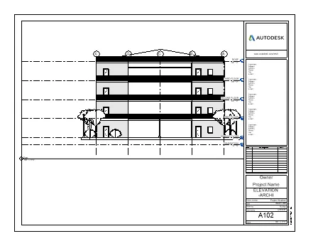
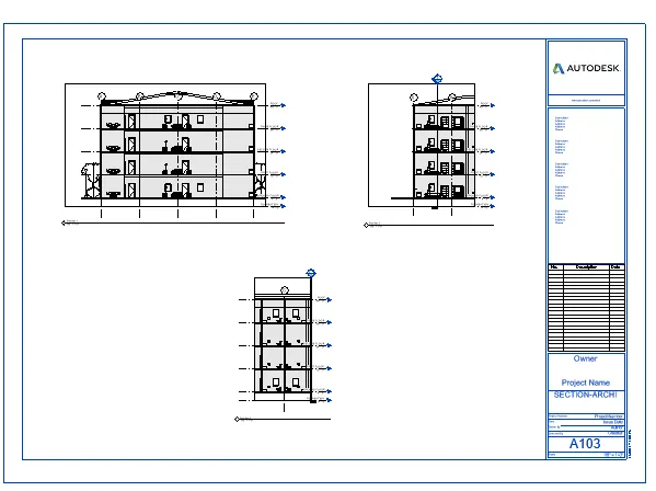
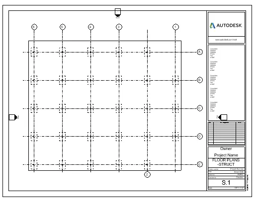
5) Provide set of drawings in architectural and structural model to list the following details with categories and appropriate sheet templates included
a. Floor Plans with Annotations
b. Elevations
c. Sections
AIM: To provide the archetctural and structural model in sheet templated imdcluded with floors,elevations.sections
TOOLS USED:
- VIEW
- SHEET TEMPLATE
- LOAD FAMILIES
- EDIT SHEETS
- PLACE VIEW
PROCEDURE:
- go to view tab
- cLiCk on sheet template
- rename the sheet as such with name of the view to be shown
- For architectural model add the views to sheets templates
- FLOOR PLAN VIEW
-
- for structural model add the views to sheet templates
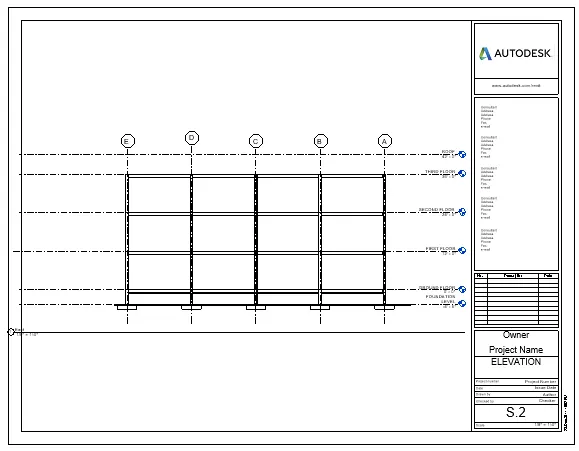
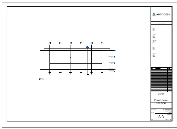
RESULT:
the given categories are included in sheet template of both archietcural and structural template
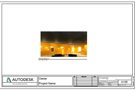
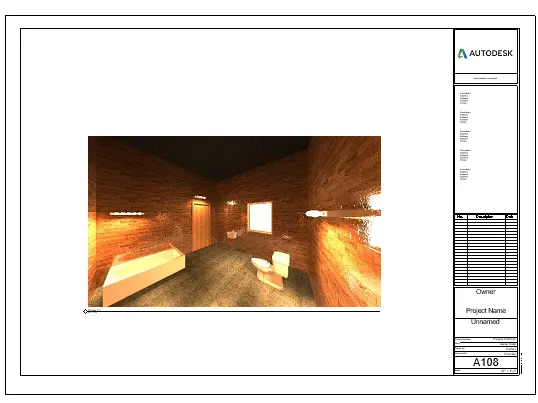
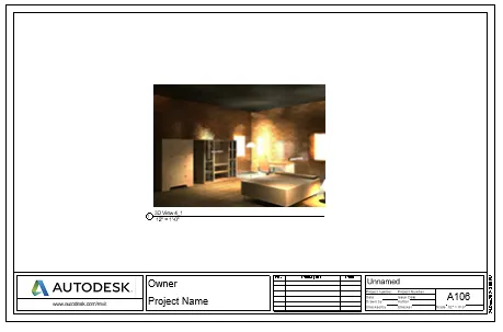
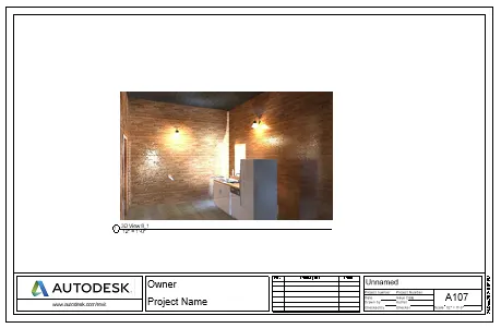
6) Using the Rendering settings, Render images of 3D model produced and include the rendered images to the drawing sheets
a. Rendering from interior rooms
b. Rendering from out showing topographic features
c. Rendering through structural framing
AIM: to renderimages of 3D model to include them into sheets
TOOLS USED:
- view
- render
- sheets
PROCEDURE:
- open the revit file
- select the 3D images
- go to view tab
- click on render command
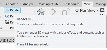
- select the properties and fix the lights corrtely with proper voltage
- adjust the exposure in dailouge box
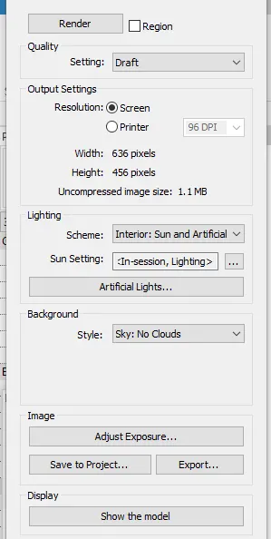
- click on save to project ,the render images will be saved
- open the sheet under view tab
- select the type of view to be included
- these rendering hepls us to view in more realistic way
a. Rendering from interior rooms
b. Rendering from out showing topographic features
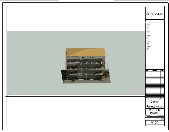
c. Rendering through structural framing
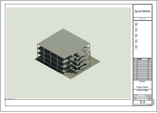
7) Print the set of drawing sheets created and submit the drawings from architecture and structure model
AIM: to print the set of drawing sheets created and submit thr drawing from architectural and structural model
TOOLS:
- file
- select page
- select plotter
PROCEDURE:
- select the view
- go to file menu and click on print
- adust the settings accordingly to print the drawings
RESULT:
SINCE,THERE IS NO PRINTER AVAILABLE ,IM UNABLE TO PRINT THEM.
drawings sheets are uploaded above question in both architetural and structual model.