REVIT_ Plan, 3D View & Structural Drawings_Project 2
- AIM: To Select the type of structure to be built.
Multi Unit Residential Apartment
b. Office Buildings
c. School
A: I select multi-unit residential apartment.
- AIM: To assume reasonable assumptions for geographic and location details for project modeling. Based on assumptions and type of structure selected identify the modeling requirements from NBC.
A: My assumptions for geographic and location details are:
- It is residential area
- Road width = 30’
- It is near plains
Modeling requirements as per NBC:
- Height of the building is as per NBC
- Size of the rooms also follows NBC
- Proper ventilation
- Proper drainage system
- AIM: Touse the structural model and to include the following components based on the type of structure selected
Foundation – Isolated / Wall/Matt Foundation
b. Columns
c. Beams Connected to Columns
d. Roof Framing/ Truss
e. Floor / Decks
f. Floor Openings for Elevators and Stairs
TOOLS REQUIRED:
- Structure tab
- View tab
PROCEDURE:
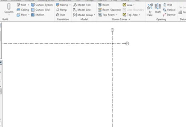
- Open structural model that is already created (central file) with a transversal grid and a longitudinal grid. And the shared co-ordinates are set to zero.
- Now set different levels for foundation, ground floor, first floor, second floor and roof.
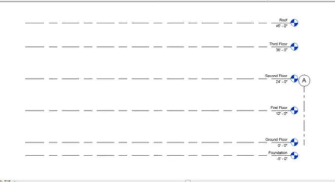
- Pin both “grid A” and “grid 1” so that characteristics doesn’t change.
- Create the grid patterns in ground floor using grids option.
- Set in equal intervals say 30’.
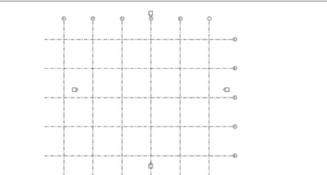
- Name transverse grids as A,B,C,D and E. and the longitudinal grids as 1,2,3,4 and 5.
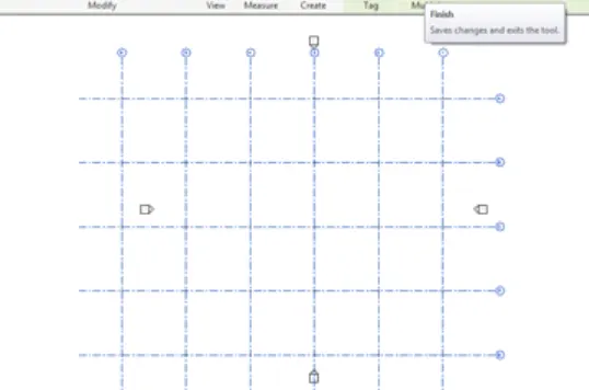
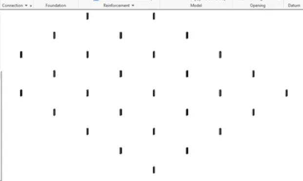
- Now click column option and select add grids to create column in the intersection of grids.
- Select all grids and click finish.
- Now columns are created that can be viewed in 3D.
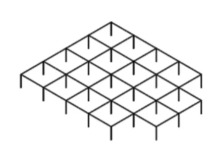
- Select beam option in architecture tab and select pick lines.
- Now create beams and can be viewed in 3D.
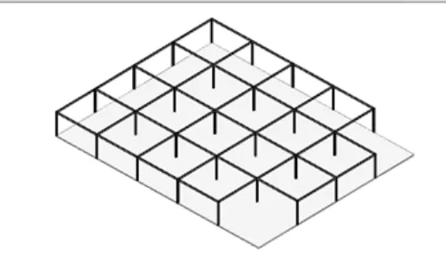
- In structure tab, select slab foundation and select pick lines.
- Now select boundary lines and click finish so that foundation is created.
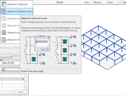
- Select total model and click filter option to remove unwanted components.
- Now click on copy option and using aligned to selected levels option and select floors and click ok. Also create floor openings for stairs and elevator.
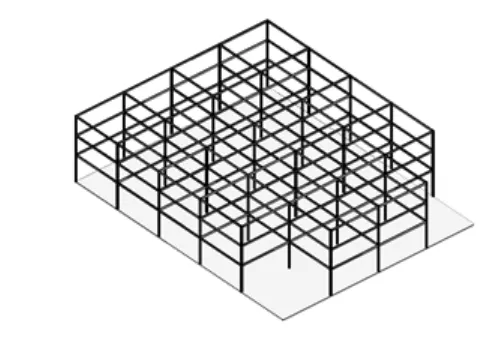
- In structure tab select floor option and using pick lines select boundary and click finish.
- Now paste the floor to different floors.
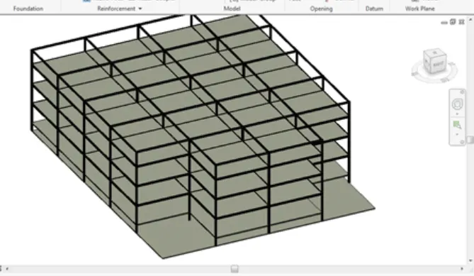
- In structure tab click on roof option and select roof by footprint option.
- Select boundary line and click finish and the roof is created.
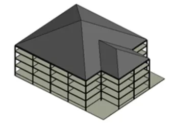
RESULT:
The structural model is created including all components.
4. AIM: To use the architectural model, and to include the following components based on the type of structure selected.
Wall Layout with appropriate material and finishing
b. Exterior façade with fancy finish
c. Interior partition walls to size rooms
d. Components to add details to room ( Desk, Chair, Lighting, Plumbing fixtures)
e. Add components such as stairs Elevators
f. Have at-least one side of building with curtain walls and glass panels
g. Include interior and exterior lighting fixtures
h. Place proper topographic components from outside ( Trees, Parking, Plants) to add details to the model
TOOLS REQUIRED:
- Architecture tab
- Properties browser
- View tab
PROCEDURE:
- Open the architectural model that is already linked to structural model. The model is already created.
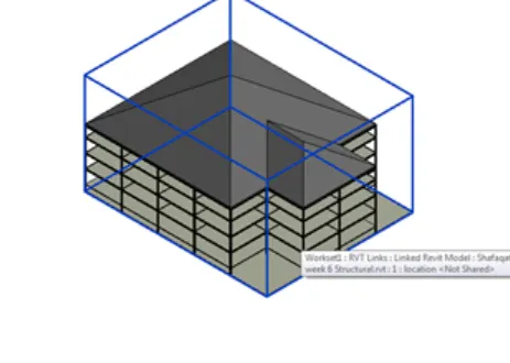
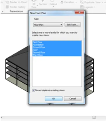
- In view tab click on plan view and select all floors and click ok.
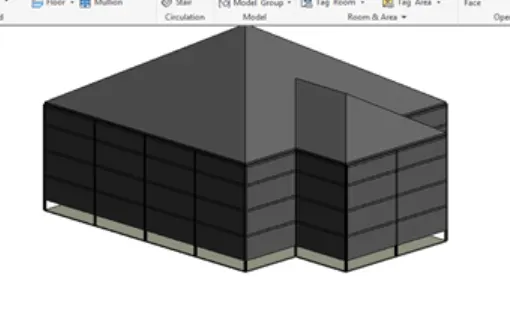
- Now in architecture tab select architectural wall and create walls such that base constraint is ground floor and top constraint is roof.
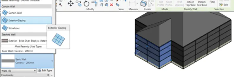
- Now click on front walls and change them to glass curtain walls.
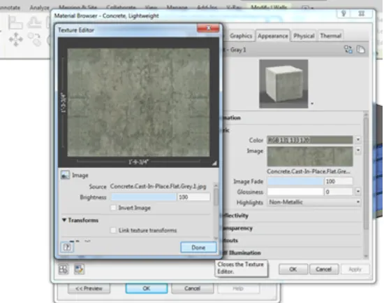
- We can also change wall material using properties.
- Now select interior walls in architecture tab and create the interior walls to create rooms in ground floor.
- Now copy interior walls and paste them to different floors.
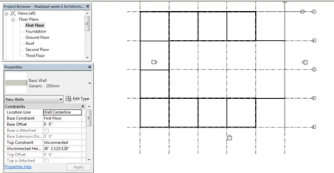
- Click on floor in architecture tab and create floor around the building.
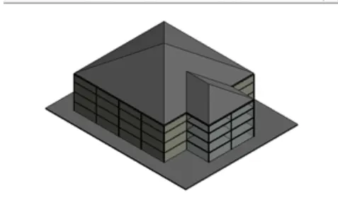
- Now using load families option, create plants and trees around the building.
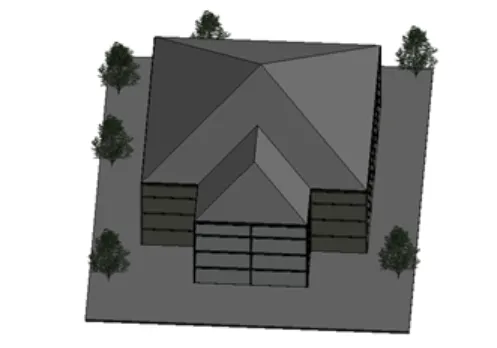
- Also create the furniture in different rooms which are required like Desk, Chair, Lighting and Plumbing fixtures.
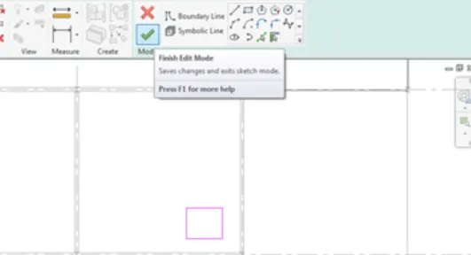
- Now create a shaft opening for elevator.
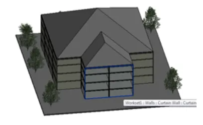
RESULT:
In the architectural model all required components are included.
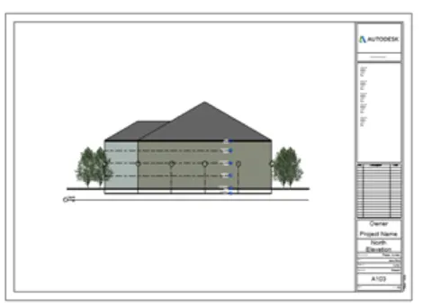
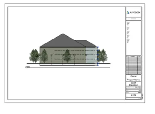
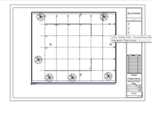
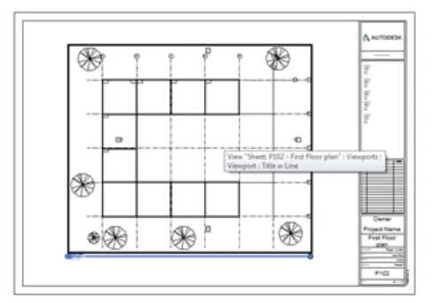
- AIM: To Provide set of drawings in architectural and structural model to list the following details with categories and appropriate sheet templates included
Floor Plans with Annotations
b. Elevations
c. Sections
TOOLS REQUIRED:
- View tab
- Sheet template
PROCEDURE:
- Open architectural model created.
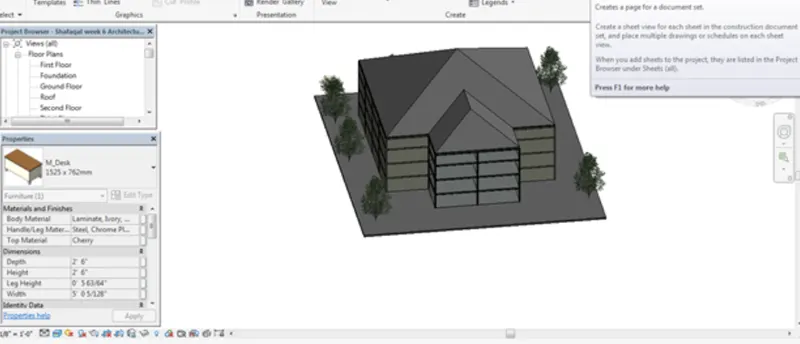
- Go to view tab and click on sheet option and create new sheet.
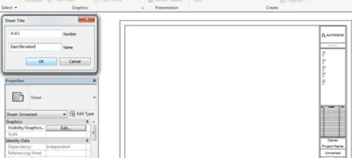
- Add all floor plans, elevations and sections in different sheets.
- Name the sheets accordingly.
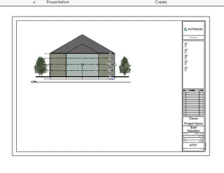
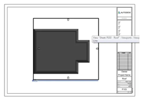
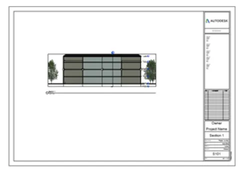
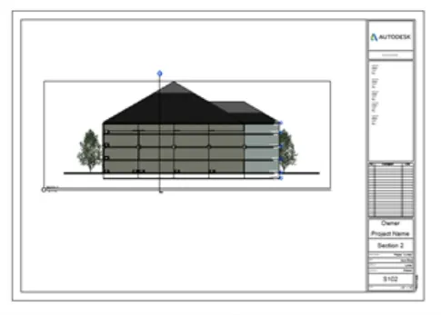
RESULT:
Sheets are created for floor plans, elevations and sections.
- AIM: To use the Rendering settings, to Render images of 3D model produced and include the rendered images to the drawing sheets
Rendering from interior rooms
b. Rendering from out showing topographic features
c. Rendering through structural framing
TOOLS REQUIRED:
- View tab
- Render option
PROCEDURE:
- Select the 3D view of front walls.
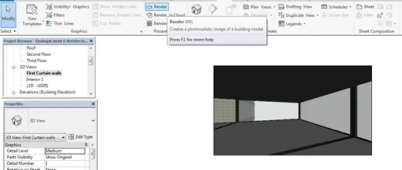
- In view tab select render option it takes some time.
- Click on save to project to save the rendered image. And also name the rendered image.
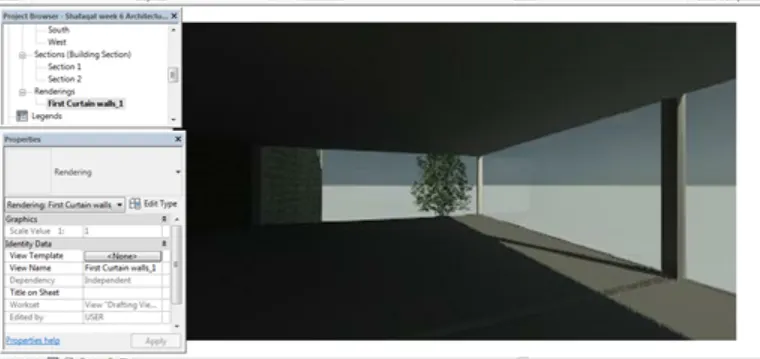
- Now in the view tab using sheet option create new sheet.
- Add the rendered image in to the sheet created.
- Do the same with all the rendered images.
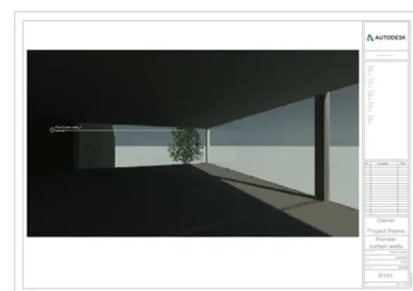
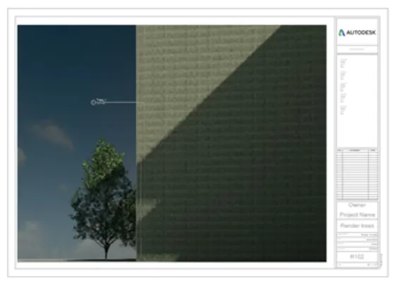
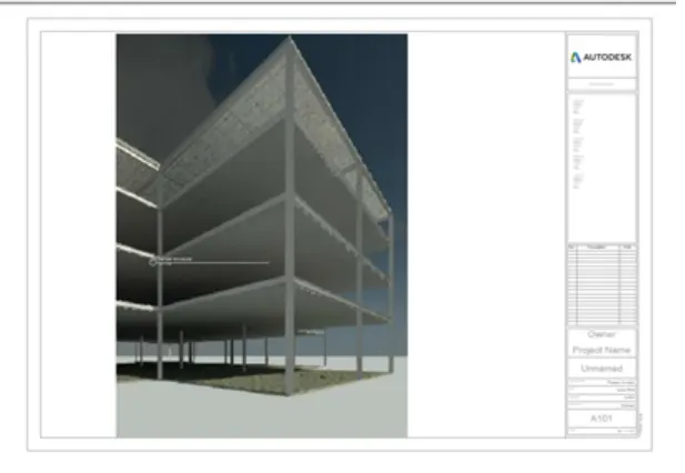
RESULT:
The images of 3D model are rendered and included in to sheets.
7. I have no printer.