REVIT_Dynamo Project- 3
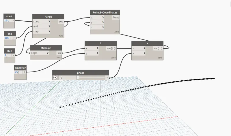
1) Using Dynamo create a set of sinusoidal points and create a curve and create a surface out of the curve.
AIM: To create a set of sinusoidal points and create a curve and create a surface out of the curve.
TOOLS REQUIRED: 1) dynamo
PROCEDURE:
1) open a new revit file.
2) open dynamo from the manage tab in the revit file
3) there exists a library in the left side of the dynamo screen
4) firstly, type code block and create 4 code blocks and name it as start, end, step value and amplifier
5) give the values to the respective code blocks
6) type range and connect the code block elements to the range such as start to start, end to end, step value to step value.
7) type points by co ordinate and connect the x to seq of range.
8) to display the angle, type formula math.sin for sinusoidal function.
9) type slider and insert a number slider and name it as phase.
10) type product and insert and connect the sin to x and amplifier to y
11) type add and insert and connect the var of product to x and phase to y.
12) connect the var of add to the y of product by coordinates.
RESULT:
2) Create a conceptual layout of floor plan in dynamo . Using the tools available in dynamo link the lines to appropriate model elements in Revit by choosing the wall types and wall parameters. Make use of the sliders to slide through the height of the wall and length of the wall.
AIM: To create a conceptual llayput of floor plan in dynamo.
TOOLS REQUIRED: 1) Dynamo
PROCEDURE:
1) Open a new revit file and open dynamo in the manage tab
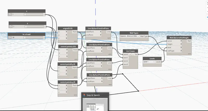
2) type points by co ordinates and select 4 times and name them accordingly as orign, control points 1,2,3 each.
3) type number slider and select 2 times and name them as x and y and connect to x in controll points 1 and 3
4) similarly select y and connect it to the y of control points 2 and 3.
5) type line in the library and insert 4 times and connect it to the point of the control points accordingly.
6) type list and add it to item 3 and connect it to respective lines.
7) type wall and insert, type wall by curve/height and insert similarly.
8) type level and insert and similarly type number slider and rename it as height of the wall.
9) now, connect wall to the wall by curve/height, level to level( in wall by curve/height), list to curve and ht of the wall to the height (in wall by curve/height)
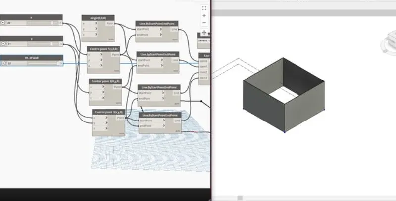
RESULT:
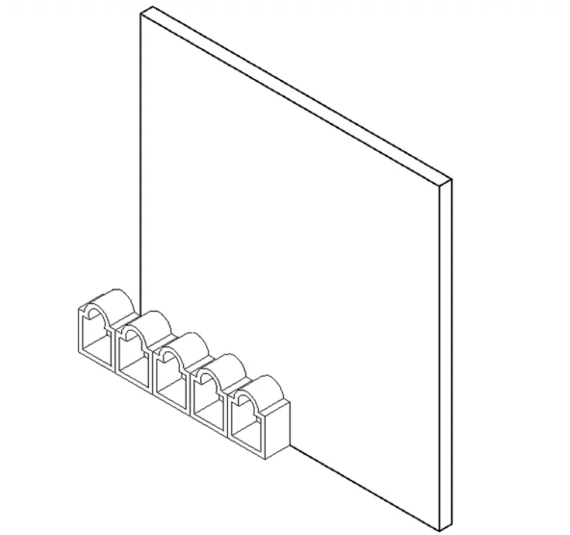
3) Create an array of model elements in Revit. Use dynamo to vary the properties of model elements by using the slider or code block
AIM:To create an array of model elements in revit using dynamo.
TOOLS REQUIRED: 1) Dynamo 2) family 3) array
PROCEDURE:
1)Open a new revit file and open a new family.
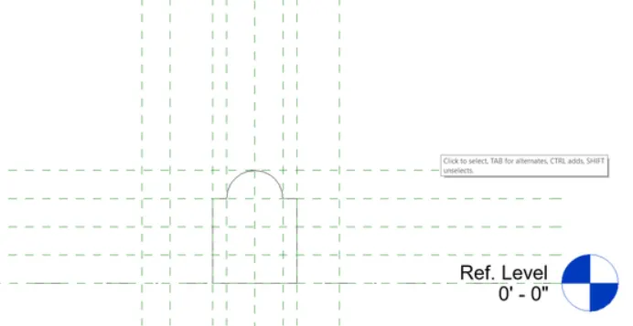
2) create a refrence plane and put offset of 6''
3) select extrusion in the create tab and select the curve and draw.
4) select the line command and draw till the middle.
5) select the mirror command by selecting all the elements.
6) using extrusion create void forms with offset 2''
7) save it and open generic model wall based.
8) select insert load into the project from the ref view
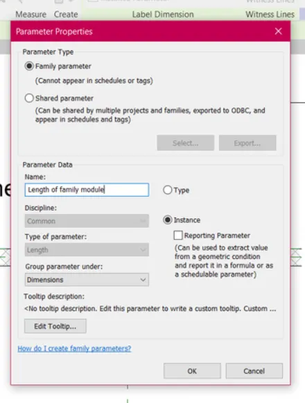
9) select the array and create a ref plane of offset 8'' and rename it as length of module from the label.
10) save it as wall shape family.
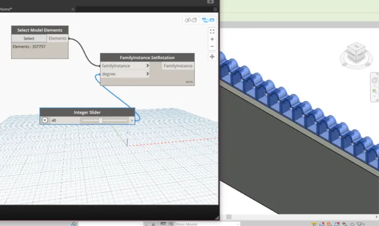
11) click on dynamo from the manage tab and type select elements and insert.
12) similarly, type rotation and insert it and type number slider and insert
13) connect the number slider to degree and connect the elements to family instances.
RESULT:
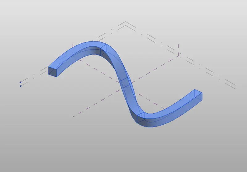
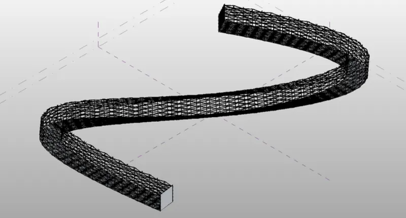
4) Create a conceptual mass in Revit and develop a parametric column by dividing the surfaces and apply the concepts similar to used in parametric walkway modelling. Use triangular bent or square shaped panels to add finish to the parametric column
AIM: To create a conceptual mass in revit and develop a parametric column by dividing the surfaces and apply the concepts similiar to used in parametric walkway modelling
TOOLS REQUIRED: 1) Family 2) spline 3) triangular bent 4) polygon
PROCEDURE:
1) Open new family and select the conceptual mass from the imperial english
2) after opening the conceptual mass, create a level of 10'
3) set the workplane in the floor plan viiew and draw draw a walkway using spline through points option.
4) set the reference by selecting the control points and select show.
5) draw rectangle in the plane in horizontal direction.10'
6) select the polygon option and insert it at the control points.
7) select the line by clicking on select the plane of all the control points and click on foam.
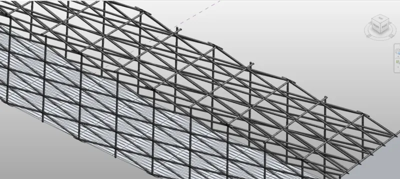
8) select the pattern as triangular bent. ( for smooth surface increase the number in grids).
RESULT: