Week 1 Challenge
13) Why do you need Collaborate tab in Revit? How it supports modelling and its efficiency
Collaborate tab helps to club all the individual works to a single unit. this is mostly used in case of big projects. the work is divided individulally and when completed individually, this tab helps to combine the individual work.By this,more people can work under the same drawing or project which makes the work more efficient.
12) What are the links that Revit supports to be linked to the model?
Links that revit supports are
1) Link topography 3) Link revit
2) Link CAD
11) What is Analyze tool bar used in Revit? How it is beneficial for design and modelling
Analyze tool bar is used to analyse the structural members when are subjected to different kinds of loadings and helps tofind the load failure in the structure.
1) From the file menu, create a new project (Structural / Architectural / Construction template ) and name the project appropriately
AIM: to create a new project from the file menu and naming the project accordingly
TOOLS REQUIRED:
1) file menu 2) new
PROCEDURE:
1) open the revit software and click on the file menu
2) click on the "new" option from the file menu and then click on project option.
3) select the template and click on browse to name it.
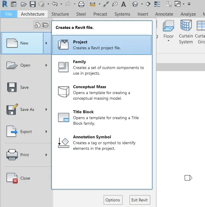
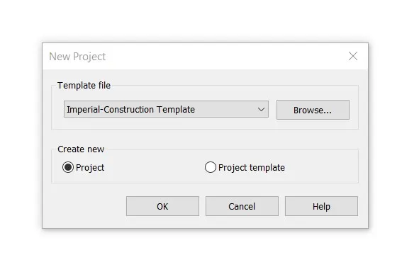
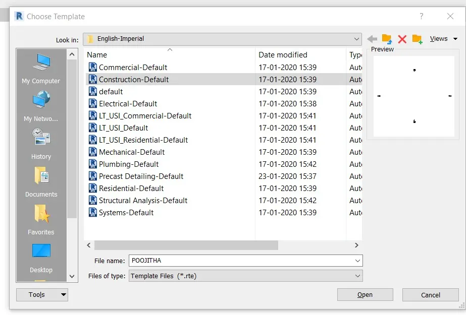
RESULT: By the above procedure, a new project is created and named.
2) Save the new project file. Close and open using icons from file toolbar
AIM: To save the new project file and to close and open using icons from the toolbar.
TOOLS REQUIRED:
1) File 2) save
PROCEDURE:
1) Click on the file menu.
2) Click on the save option from the file menu and click on the option where you to save your file.
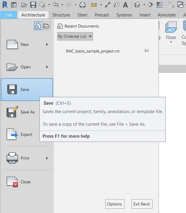
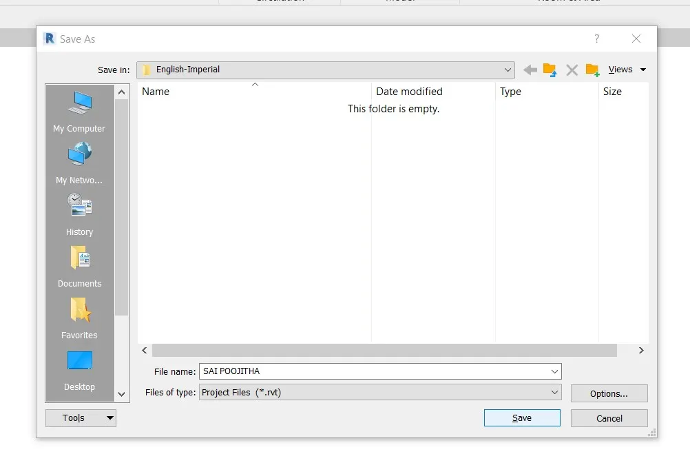
RESULT: The new project file is saved.
3) From the architecture/ structure tool bar familiarize with options to draw a wall. Create a rectangular layout of walls of about 40’-0” X 35’-0”
AIM: To draw a wall and create a rectangular layout of walls of about 40'x35'
TOOLS REQUIRED:
1) File 2) Wall
PROCEDURE:
1) Create a new project and then select the template as architectural.
2) Click on the wall option and specify the first point.
3) Type 40' in X direction and enter then type 35' in y direction and press enter button.
4) Similarly, type 40' in x direction and 35' in y direction to form a rectangular layout.
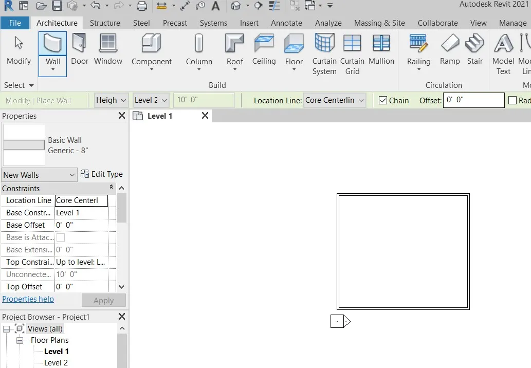
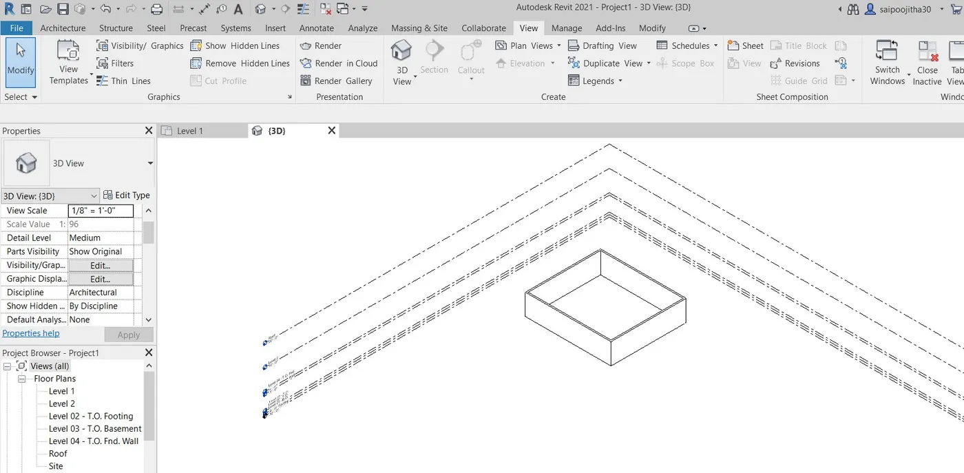
RESULT: Wall is created.
4) From Annotate tool bar use aligned option to add dimensions to the layout
AIM: To add the dimensions to the layout.
TOOLS REQUIRED:
1) Annotate 2) aligned
PROCEDURE:
1) Select the annotate tab.
2) click on the aligned option from the annotate tab.
3) place the cursor one on end of the line and move it to the other end of the line to get the dimesions.
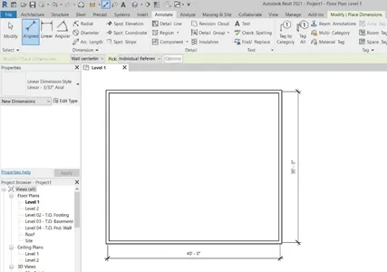
RESULT: Dimensions are marked for the layout.
5) Use the properties browser to switch to different wall types
AIM: To use the properties browser to switch to different wall tyoes.
TOOLS REQUIRED:
1) Properties in the extreme left.
PROCEDURE:
1) Change the wall from 2D view to 3D view and select the wall.
2) select the desired wall from the properties which appear on the left.
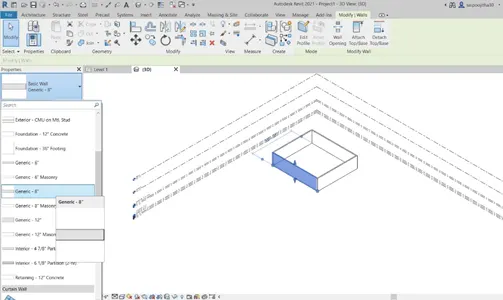
RESULT: Switching to different types of walls is done by using properties browser.
6) Create a 3D view from the view tool bar and save the view with appropriate name
AIM: To create a 3D view from the view tool bar and save the view with appropriate name.
TOOLS REQUIRED:
1) View 2) 3D 3) save 4)rename
PROCEDURE:
1) Select the 3D view.
2) by right clicking. there's a option to save view
3) rename the view.
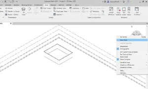
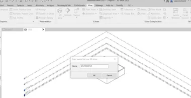
RESULT: 3D view is created and saved.
7) Navigate through the 3D model using view cube. Orbit/pan through the model layout created
AIM: To navigate through the 3D model using view cube and to orbit/pan through the model layout.
TOOLS REQUIRED:
1) View 2) Navigation wheel
PROCEDURE:
1) Select the 3D view and click on the navigation wheel which is present on the extreme right.
2) select the view to look in the desired direction.
3) move the object in any direction to see the object in 360' view.
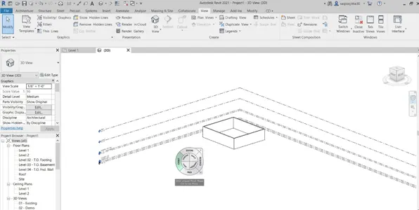
RESULT: Navigated through the 3D model using view cube.
8) Use the visibility settings option below to switch model to shaded, realistic, hidden lines options
AIM: To use the visibility settings option below to switch model to shaded, realistic, hidden lines options.
TOOLS REQUIRED:
1) Visibility
PROCEDURE:
1) Select the 3D view.
2) at the extreme bottom there's an icon which is visual styles. click on that to get the required shade.
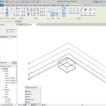
RESULT: the visibility settings option is used.
10) Use the Manage tool bar to enter project settings, project name and project issue date (choose according to your convenience).
AIM: To use the manage tool bar to enter project settings, project name and project issue date.
TOOLS REQUIRED:
1) Manage tool 2) project information
PROCEDURE:
1) Click on the manage tool bar and go to the project information.
2) write the details of the project such as name and issue date etc.
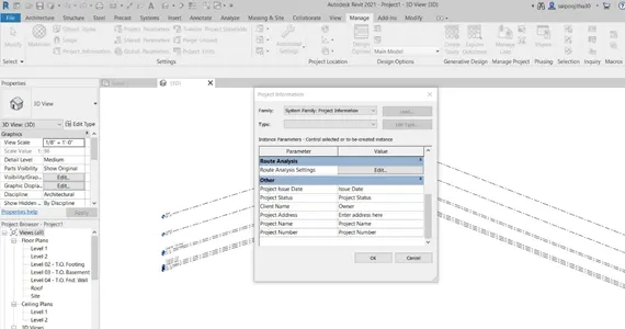
RESULT: Project name and project issue date are entered.
9) Turn the sunlight on and off to view shadings in the layout created
AIM: To turn the sunlight on and off to view shadings in the layout created
TOOLS REQUIRED:
1) Manage 2) Additional command
PROCEDURE:
1) select the manage option and select the additional settings
2) select the solar study option from the additional settings.
3) On the sunpath and click ok
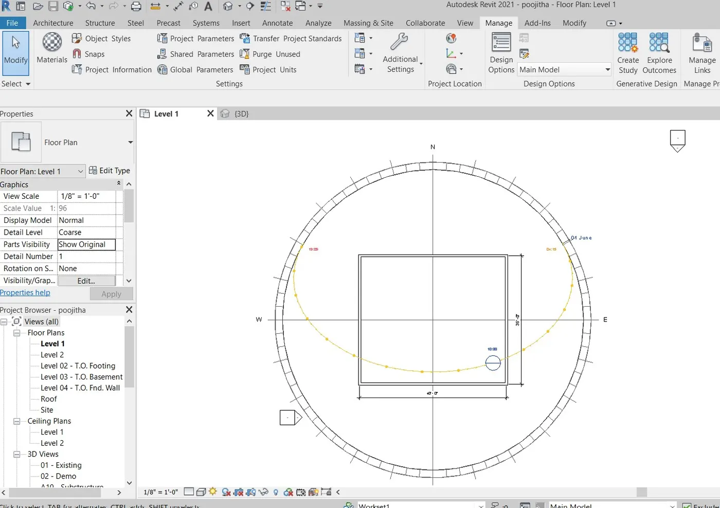
RESULT: sunlight settings are turned on and off