Reinforcement detailing of Columns from ETABS output
Aim:
Reinforcement detailing of columns in Etabs .
The ETABS file for a G+4 building is provided. Run the analysis and design the RCC Moment Resisting Frame. The following challenge deals specifically with two columns at the following grid intersections.
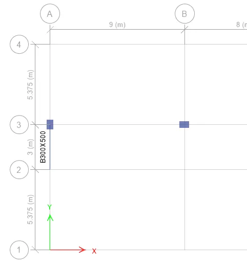
- 3A
- 3B
- Provide details of longitudinal reinforcement for the two columns, from foundation to terrace level. Sketch the column cross sectional & elevation details or draft it using autocad software.
- Show shear reinforcement & lapping details as per special confining reinforcement provision of clause 8.1 of IS 13920 - 2016.
INTRODUCTION:
Detailing rule of any Reinforced concrete member:
1. Minimum reinforcement for shrinkage & temperature
2. Ultimate limit state design rebar requirement
3. Ductility rebar requirement
(Whichever is greater, Should be drawn in RC column detailing)
- Minimum longitudinal reinforcement as per IS-456-2000 clause 26.5.3.1 A 2340 mm2
- Minimum shear (or) transverse reinforcement as per IS-13920-2016 clause 7.4.2 - 8mm dia at 300mm spacing
- Development length as per IS-456-2000 clause 26.2.1 L = 41 x diameter of bar
PROCEDURE :
Design of RC columns:
Step-1:
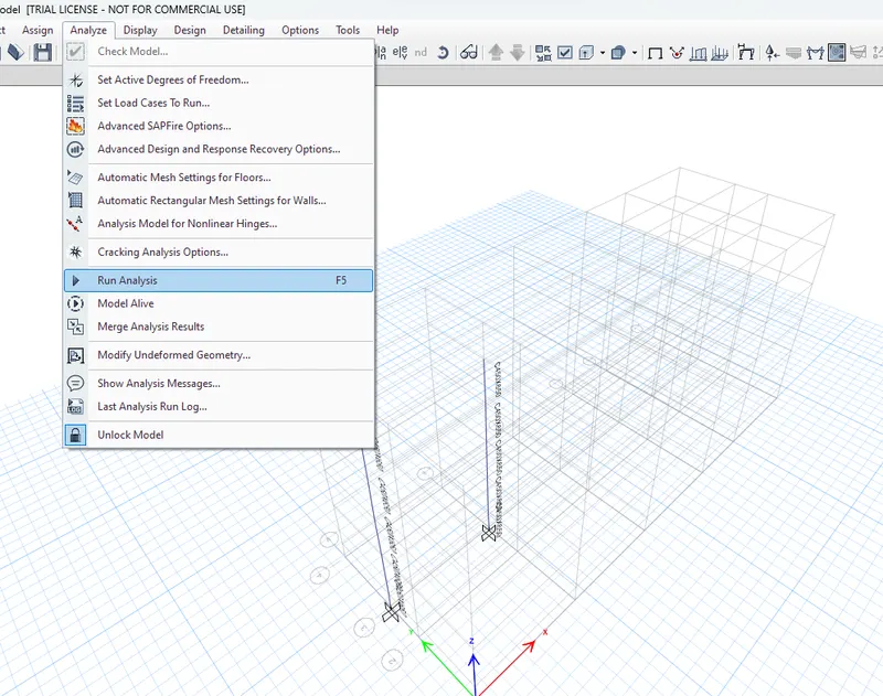
- Go to analyse tab , then go to check Model
- Now select the Frames
- After selecting , run the analysis
Step-2:
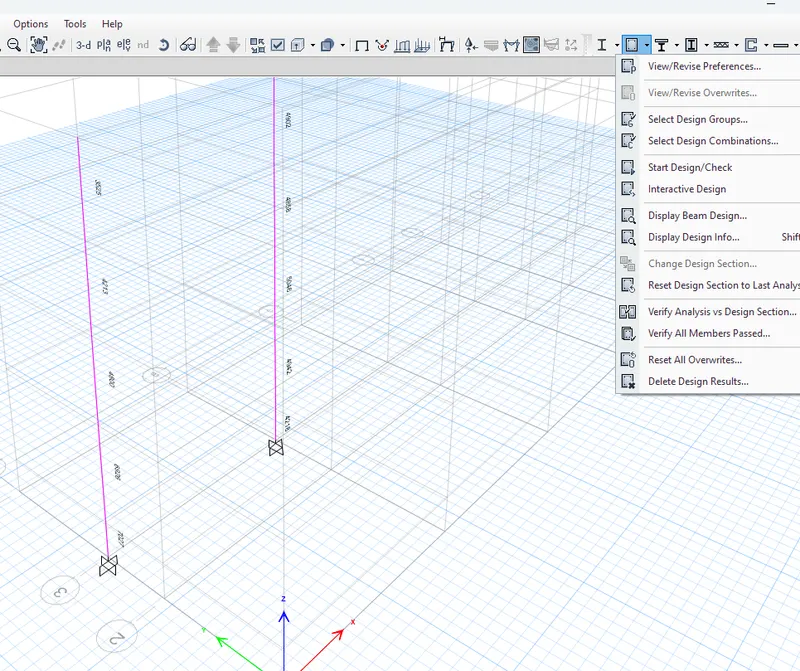
- Go to the Design tab and then go Frame Design Preference
- Now go to Concrete Frame Design Combination, then click on Star Design
- Using the above toolpath, the given ETABS model is ensured for its design code assignment and combination assignments. Then the ETABS model is design initiated
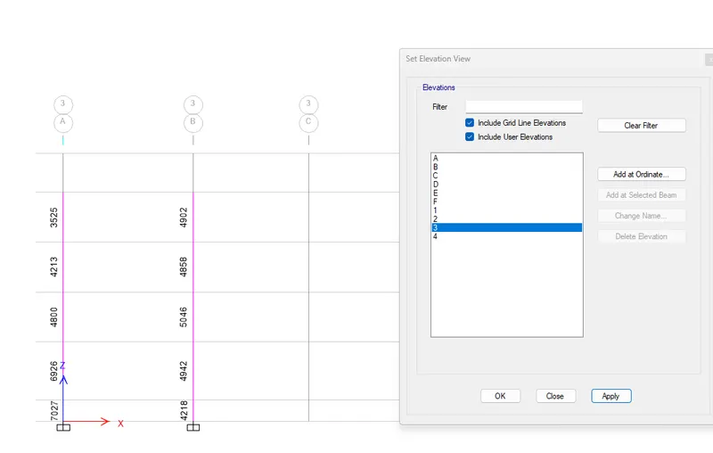
Step-3:
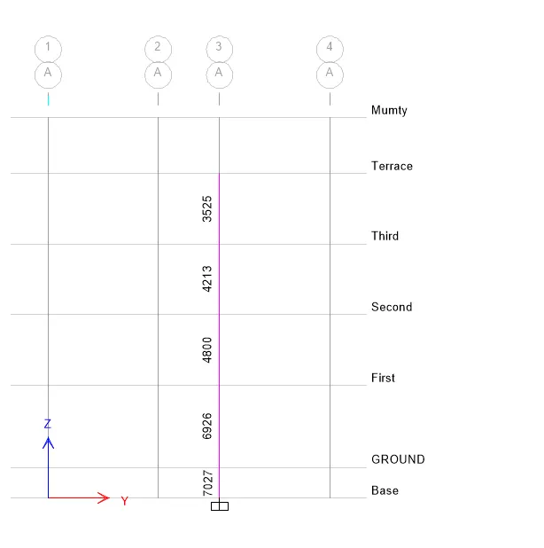
- Go to Design tab , then go to Verify all members passed
- Now click on the Display design info ,then go to Flexural reinforcement
- Ater that go to the Display design info , then click on Shear reinforcement
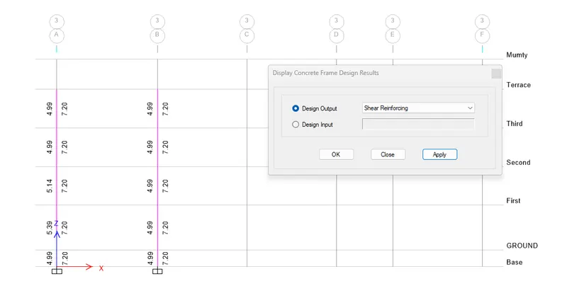
- As per the noted rebar outputs, the Longitudinal sections for those two RC beams are drawn using AutoCAD software and detailing is done complying IS 13920-2016 requirements
- As per clause 8.1 of IS13920-2016, the special confining reinforcement is calculated and verified with the drawing detail.
- As per cluase 8.1 section a), the confining reinforcement length Lo should be at least of below three :
i) larger dimension of frame member (650mm)
ii) 1/6th of clear span (575mm)
iii) 450mm
So ; Lo= 650mm
- As per cluase 8.1 section b), the maximum spacing of confining reinforcement shall be
i) 1/4th of minimum member dimension (112.5mm)
ii) 6 times of smallest longitudinal rebar (120mm)
iii) 100mm
So maximum shear link spacing maintained = 100mm
Minimum special confining reinforcement should be maximum of (a) or (b)
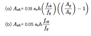
(a) Ash= 632
(b) Ash= 337
Therefore ; Ash =632 sq mm/m