Reinforcement Detailing of Beams from ETABS output
Challenge 7
Detailed design of concrete buildings -1
Detail design of beams in Etabs 2018.
The ETABS file for a G+4 building is provided. Run the analysis and design the RCC Moment ResistingFrame. The following challenge deals specifically with two continuous beams in the 1st floor.
1) 3 span continuous beam along grid A
2) 7 span continuous beam along grid 3
Address the following issues thereafter.
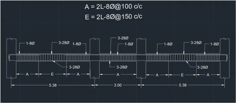
- Provide details of longitudinal and shear reinforcement for the two continuous beams. Sketch the beam elevation details or draft it using autocad software. A sample of how beam elevation details is prepared in consultancy firms is provided below. Participants can prepare it as per their preference:
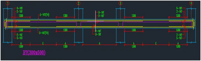
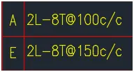
- Provide reasons for failure of the middle span along grid A. What are the possible ways this issue can be resolved?
- Calculate value of the maximum shear force in any one of the spans in both the continuous beams, as per clause 6.3.3 (b) in IS 13920 – 2016. Also, confirm these values from shear force demand calculated by ETABS.Please note that if longitudinal reinforcement provided is more than required (as per ETABS results), the shear force demand will vary from what is provided by ETABS.
Aim :-
- To design the beams in ETabs.
- To provide details of longitudinal and shear reinforcement for the two continuous beams and Calculate value of the maximum shear force in any one of the spans in both the continuous beams.
Procedure :-
- First we have to open the challenge 7 page and download the challenge.
- After downloading the challenge open it in ETabs, as shown below.
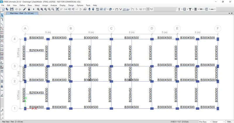
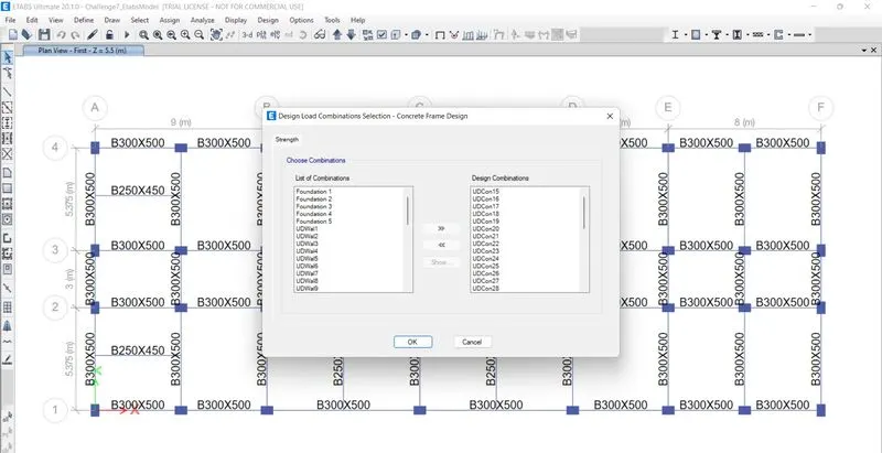
- Next we have to check the load combinations, as shown below.
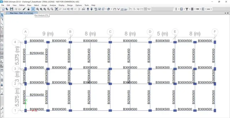
- Next we have to Run the analysis.
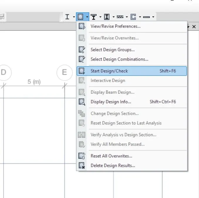
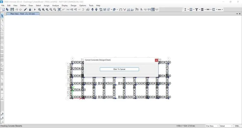
- Next we have to start the beam design by selecting 'start design/check' option, as shown below.
- After the completion of beam design, we need to select the 'Display Design information', as shown below.
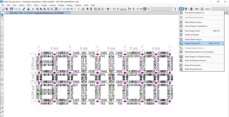
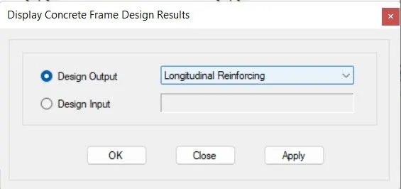
- After selecting the 'Display Design info' option the new tab appears, in that we select the longitudinal reinforcement in the design output and click on the ok button, as shown below.
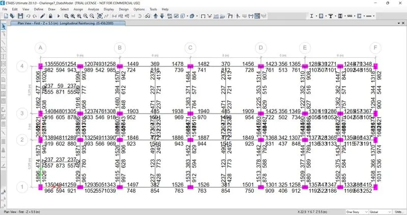
- Next the longitudinal reinforcement details will appear, as shown below.
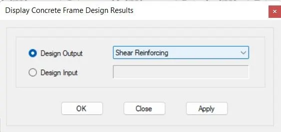
- After selecting the 'Display Design info' option the new tab appears, in that we select the Shear reinforcement in the design output and click on the ok button, as shown below.
- Next the Shear reinforcement details will appear, as shown below.
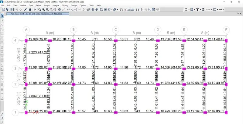
- Now we need to draw the reinforcement diagram of 3-span continuous along Grid-A and also need to provide the reinforcement details.
- The maximum Ast for the Bottom support is 1862 mm2 and bottom middle is 789 mm2.
- The maximum Ast for the Top support is 1873 mm2 and bottom middle is 477 mm2.
- now we provide 3-28 diameter at the top and bottom, as shown in below Figure .
- Now we provide 1-8 diameter top support for the continuous beam as shown below.
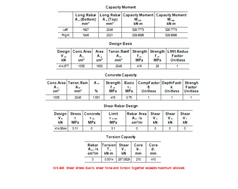
Provide reasons for failure of the middle span along grid A. What are the possible ways this issue can be resolved?
- The central span of grid-A RC beam is failing due to higher shear stress.
- As per the above force value against maximum allowable shear stress (3.1MPa) is failing.
- This design shear force is arrived in Philosophy of capacity design concept.
It can be resolved by,
- Optimising provide flexturer reinforcement.
- Reducing the depth of RC beam which in turn reduce stiffness and flexural requirement.
- Increasing concrete grade will increase allowable shear limit.
Calculate value of the maximum shear force in any one of the spans in both the continuous beams, as per clause 6.3.3 (b) in IS 13920 – 2016. Also, confirm these values from shear force demand calculated by ETABS.Please note that if longitudinal reinforcement provided is more than required (as per ETABS results), the shear force demand will vary from what is provided by ETABS.
- After providing the beam reinforcement detail, we select the beam and right click on the beam then the new tab appears as shown below.
- Next we need to click on the details option in concrete beam design tab.
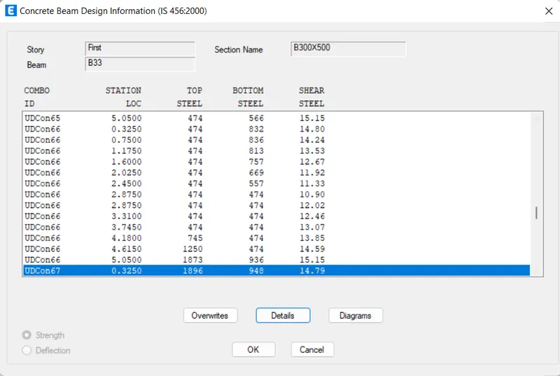
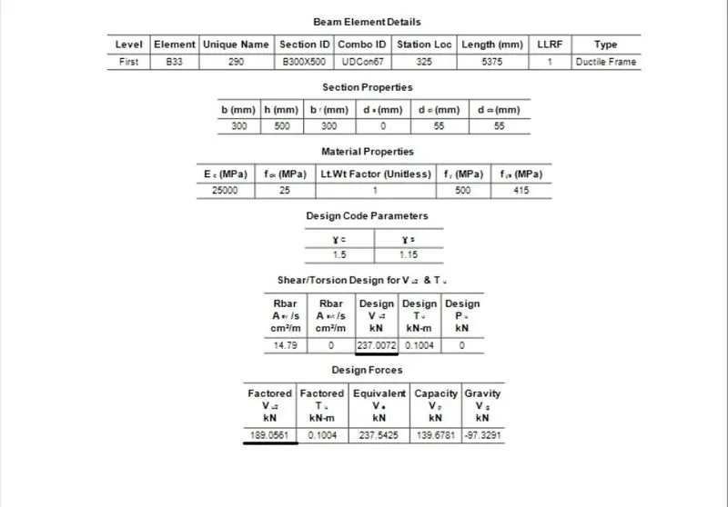
- Next the shear details will be visible, as Shown below.
- As per clause 6.3.3 (b) in IS 13920 – 2016, the design forces = 237 KN
- We got maximum shear force = 189 KN.
Result :-
- The beams are designed successfully in detail from ETabs Software.
- Provided details of longitudinal and shear reinforcement for the two continuous beams and Calculated value of the maximum shear force in any one of the spans in both the continuous beams.