Reinforcement Detailing of Beams from ETABS output
Ans-
Aim - Detailed designed of RCC Beam in ETABS and reinforcement detailing.
Procedure-
- First download ETABS file and save then run for analysis.
- Go to Design option – concrete frame design- start design then go to design info and design longitudinal reinforcement and shear reinforcement.
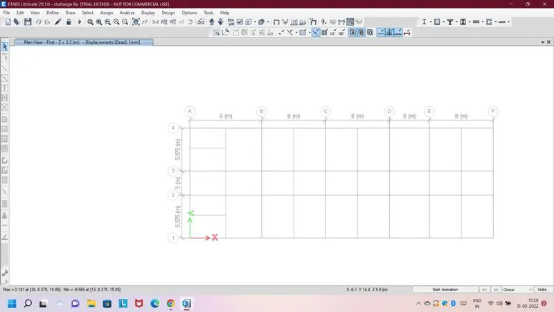
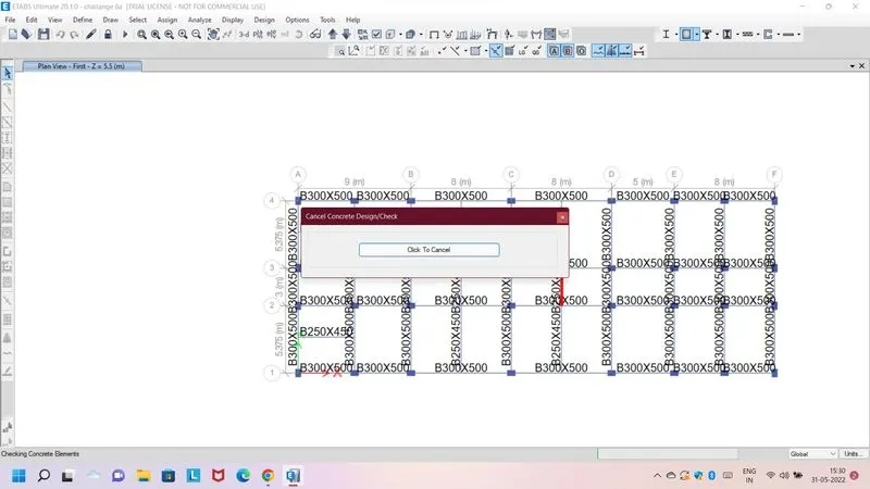
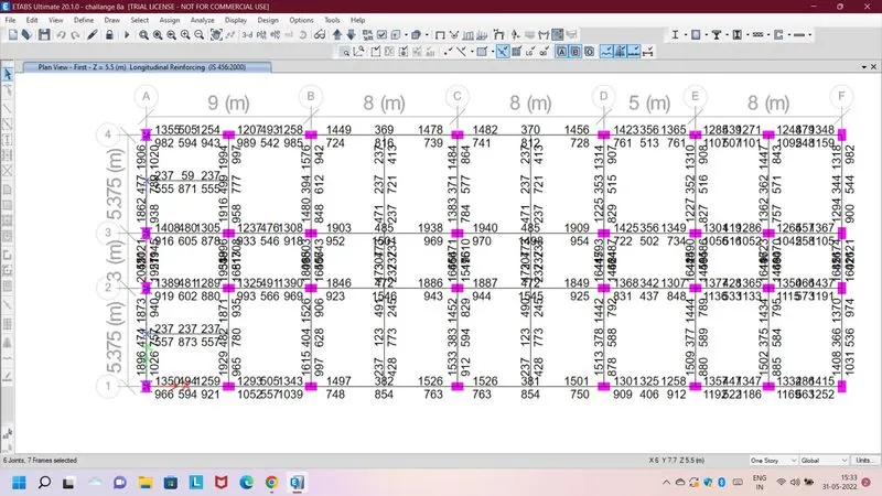
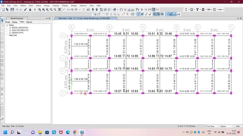
As per question we are selecting to continuous beam-
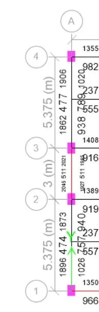
- Along Grid A 3 span beam required reinforcement detail
Longitudinal R/f-
Shear Reeinforcement
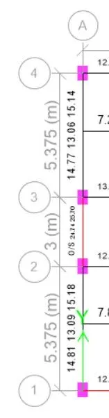
Along Grid 3 Longitudinal and shear required reinforcement of 7 span beam


Detailing rule of any reinforced concrete member-
- Minimum reinforcement for shrinkage & temperature.
- Ultimate limit state design rebar requirement
- Ductility rebar requirement
Which is greater in above should be drawn in RC.
Grid A Beam data-
Beam size-300X500 mm, Grade of conc- 25 mpa, Long r/f- fe500, Shear r/f -Fe415, Effective depth of beam- 450mm.
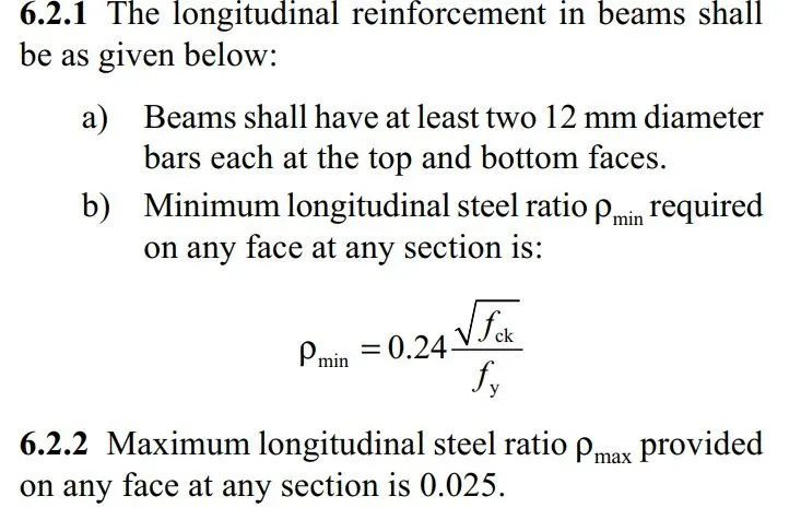
- As per IS-13920-2016 clause-6.2.1
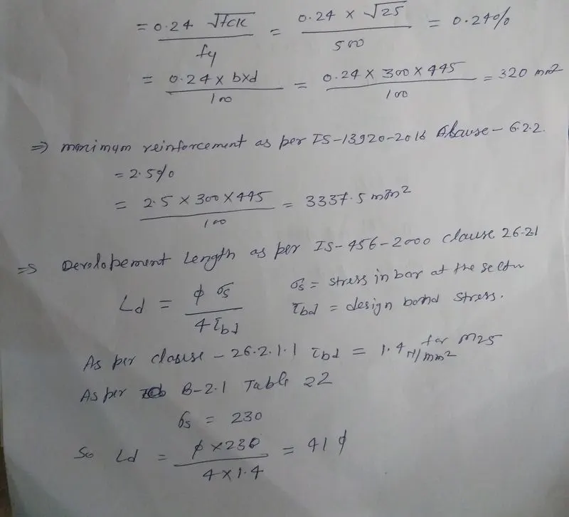
So minimum r/f = 332 Sq mm
maximum r/f =3338 sq mm
Devlopment length =41 D
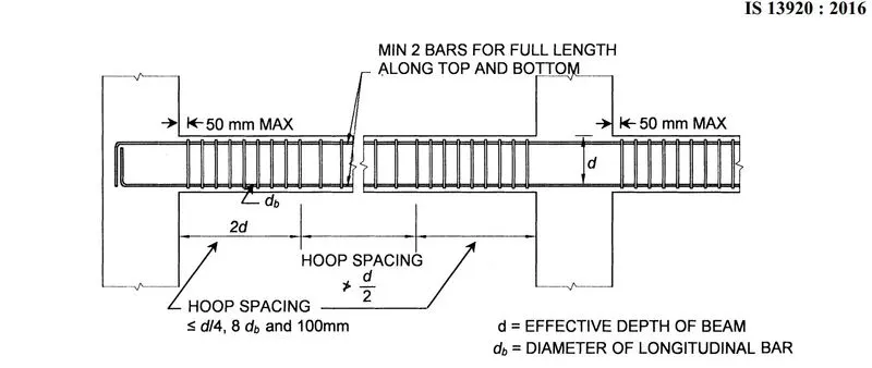
Additional r/f guideline from IS 13920-2016 clause6-
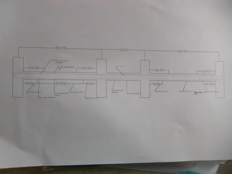
Sketch of reinforcement detail of grid A beam-
Additional check as per IS 13920-2016 Clause 6.3.3-
1) Sway shear force to right
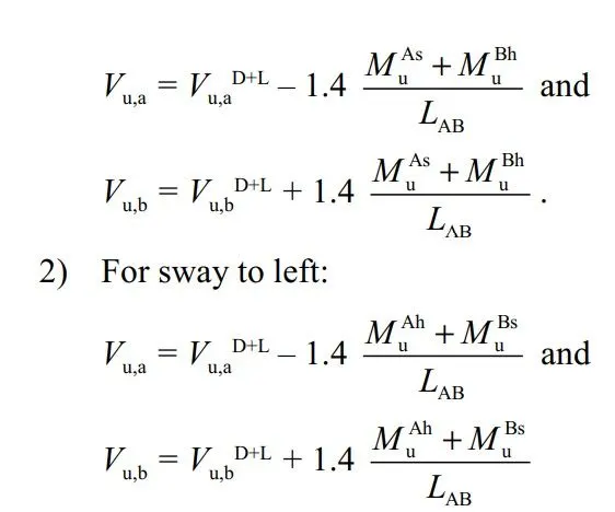
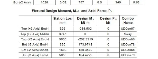
From Etabs Envelope option -
Force to Right Force to Left
Mas=173.97 kNm Mah=234 kNm
Mbh=292.99 kNm Mbs=155 Knm
Vd+l=92 KN Vd+l=70Kn
Lab= 4.725 m Lab=4.725 m
After Calculation
Vua=46 Kn Vua= 185 KN
Vub=230Kn Vub=45 KN
Existing shear capacity in beam as per IS456-2000-
Vus =(0.87XfyXAsvXd)/Sv
=245 Kn
Reason for failure of the mid span- The beam along grid A at the mid span failed due to overstress , beacuse the stress has increased allowable stress, so reduce or increased loading or used higher grade of concrete.