Reinforcement Detailing of Beams from ETABS output
Aim- to analyse the given ETABS model and provide reinforcement details for two mentioned Beams.
Procedure-
- Open the Etabs software.
- And open the given file in the etabs.
- Go to first floor in plan view.
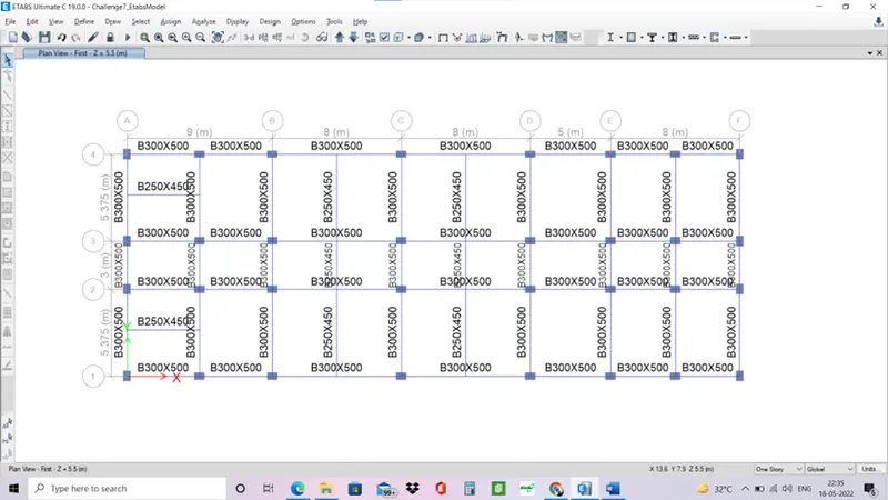
- Analyse the model.
- Run analysis of the model.
- The model is checked for errors and warnings and analysis is run on the model.
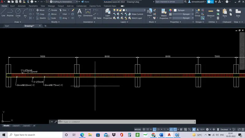
- Provide details of longitudinal and shear reinforcement for the two continuous beams. Sketch the beam elevation details or draft it using autocad software. A sample of how beam elevation details is prepared in consultancy firms is provided below. Participants can prepare it as per their preference:
- Now beam design is to be done.
- Go to concrete frame design in toolbar> start design check.
- Then go to display design info> longitudinal reinforcement.
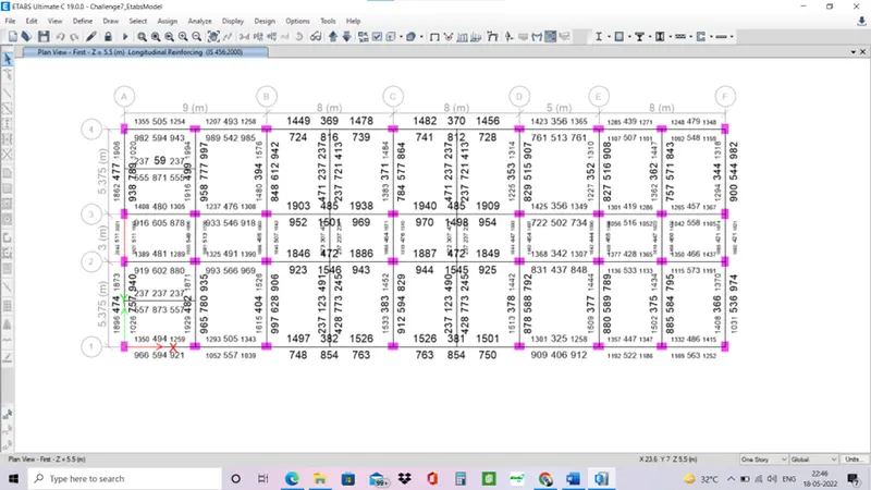
- Display design info> shear reinforcement.
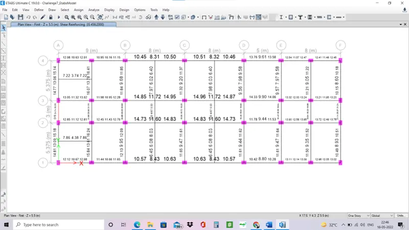
Reinforcement details of beams.
On grid A
At top
- maximum Ast required at support is 2045 mm2.
- maximum Ast required in middle is 511 mm2.
Reinforcement to be provided
- 2 bars of 32mmØ
- 1 bar of 25mmØ
At bottom
- maximum Ast required at support is 1945 mm2.
- maximum Ast required in middle is 789 mm2.
Reinforcement to be provided
- 2 bars of 32mmØ
- 1 bar of 25mmØ
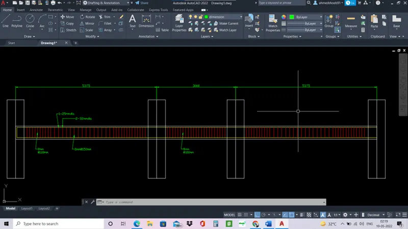
On grid 3
At top
- maximum Ast required at support is 1940 mm2.
- maximum Ast required in middle is 485 mm2.
Reinforcement to be provided
- 2 bars of 32mmØ
- 1 bar of 25mmØ
At bottom
- maximum Ast required at support is 1056 mm2.
- maximum Ast required in middle is 1501 mm2.
Reinforcement to be provided
- 3 bars of 25mmØ.
- Provide reasons for failure of the middle span along grid A. What are the possible ways this issue can be resolved?
- Beam in grid A between 2 and 3 is failing due to shear stress.
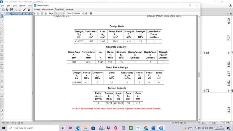
- We can see shear stress limit is 3.1 MPa but shear stress in beam is slightly exceeding with 3.1 MPa.
- Concrete design from M25 to M30 can be provided for the beam to avoid shear stress failure as it increases shear capacity of concrete.
- decreasing the loads on the beam and increasing the area of the beam could also be helpfull.
Calculate value of the maximum shear force in any one of the spans in both the continuous beams, as per clause 6.3.3 (b) in IS 13920 – 2016. Also, confirm these values from shear force demand calculated by ETABS.Please note that if longitudinal reinforcement provided is more than required (as per ETABS results), the shear force demand will vary from what is provided by ETABS.
- As per IS 13920-2016 clause 6.3.3 (b).
- Right click on any beam and select shear detail.
- Hear hogging and sagging moment will be provided.
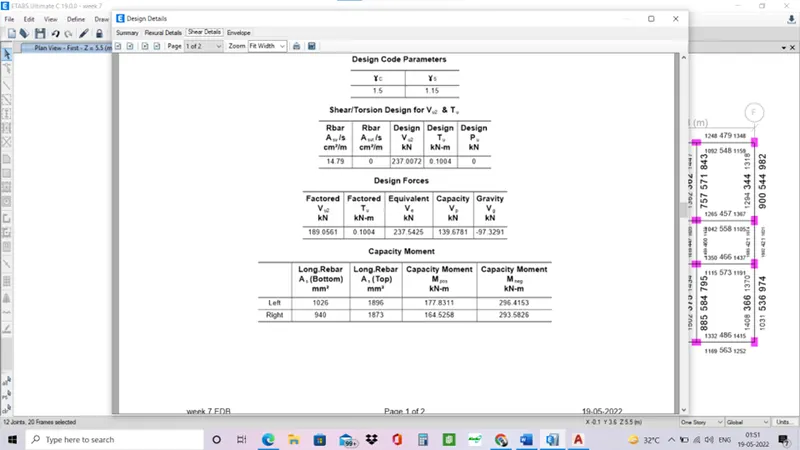
- Substitute in the shear sway to right and left formula with factored dead and live load of 1.2.
- Max shear force is at right at end B = 230kn.
- Etabs design value gives a max shear force value of 237kn