Reinforcement Detailing of Beams from ETABS output
AIM: -
To design the beams in detail from the ETABS 2018.
To provide details of longitudinal and shear reinforcement for the give two continuous beams.
To calculate the value of maximum shear force in any one of the spans in the continuous beams.
INTRODUCTION: -
- Beams are horizontal structural elements used for supporting lateral loads.
- In conventional reinforced concrete structures, beams usually receive load from the floor slab, but may also be subjected to other loads such as wall loads, finishes, services installation, etc.
- The design and detailing of RC beams involve the selection of the proper beam size and the quantity of longitudinal and shear reinforcement that will satisfy ultimate and serviceability limit state requirements.
- Afterwards, it is very important that the beam reinforcements are placed and arranged properly on site, to avoid construction error.
Procedure: -
- First of all, download the attachment provided in the question.
- Open the file in the ETABS software as shown in image below.
- Before designing the structure let us run the analysis first.
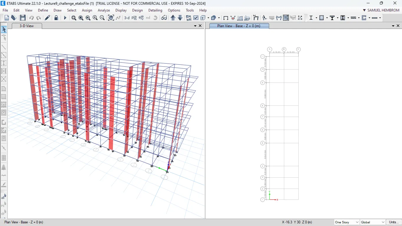
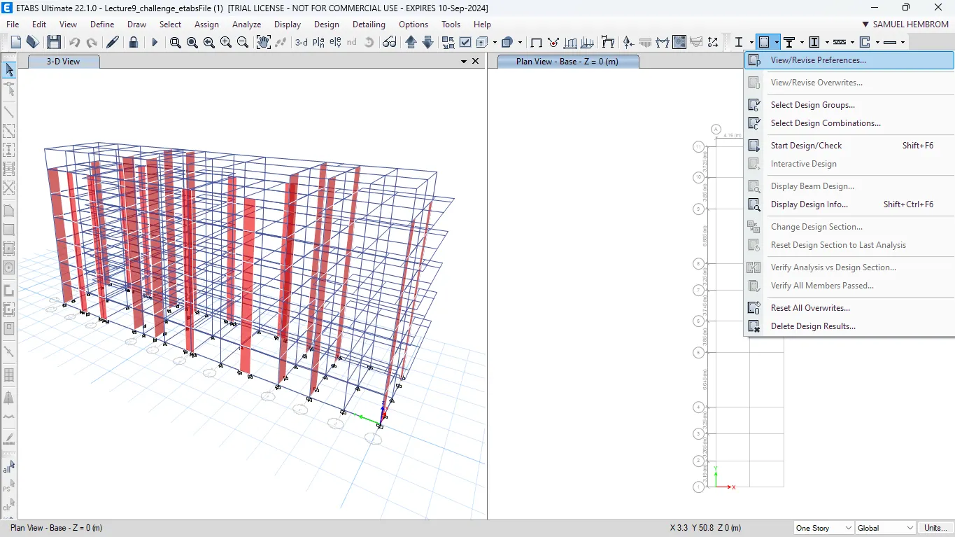
- Next go to the "Concrete Frame Design" icon in the icon's toolbar and select "view/revise preferences" from the drop-down menu.
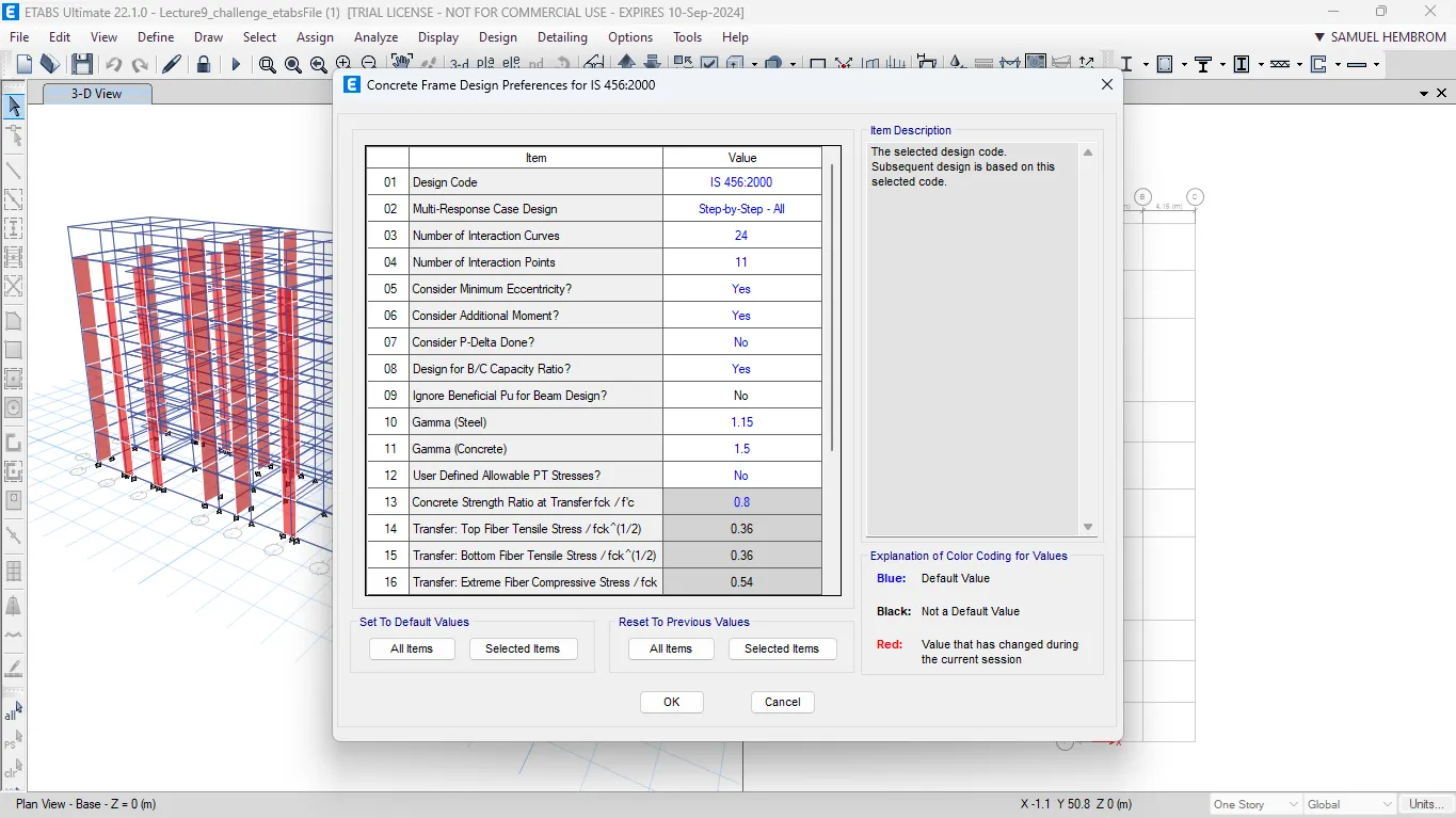
- Check for the default setting in the next dialogue box and keep it as it is.
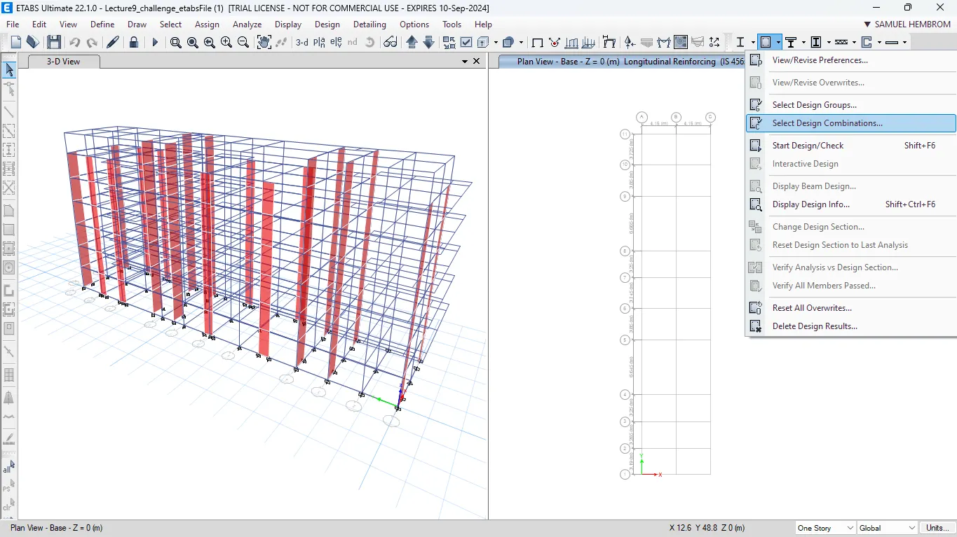
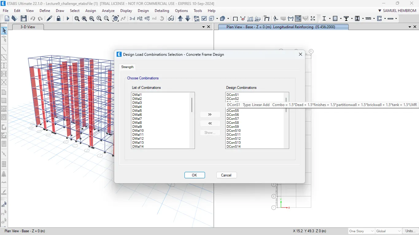
- Now we have to check for design combinations.
- For that click on the arrow pointing downwards next to "Concrete Frame Design" icon in the icon's toolbar.
- And click on "Select Design Combinations" option from the drop-down menu.
- In the next dialogue box check for all the design combinations for which analysis could be done.
- Usually, the correct way is running earthquake load combination separately from gravity load combination.
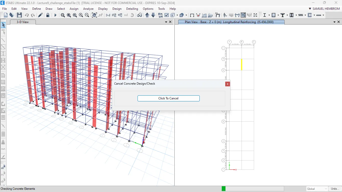
- Now run the design frame analysis by clicking on the "concrete frame design" icon in the icon's toolbar.

- Below image shows the result after the completion of the analysis.
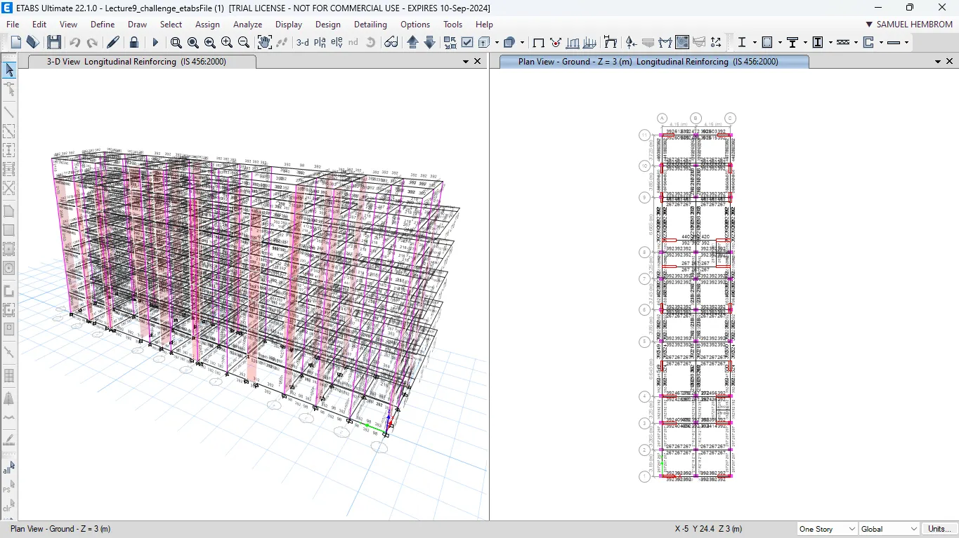
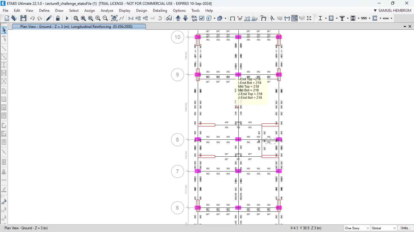
- The numbers shown are basically longitudinal steel requirements in all the beams mentioned.
- Now for checking the different design info click on the arrow pointing downwards next to the "Concrete frame design" icon in the icon's toolbar.
- From the drop-down menu click on the "Display Design Info".
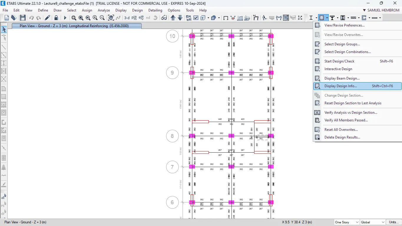
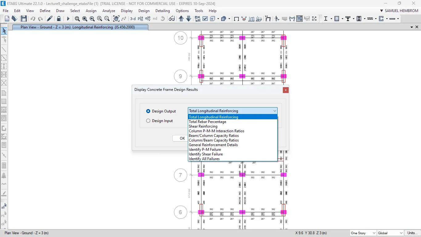
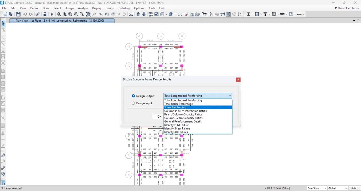
- In the next dialogue box, we can see different type of design info. By default, design info is shown for longitudinal reinforcement. For any other design info such as shear reinforcing just choose it from the drop-down menu as shown in image below.
- Following is the Design result for Total Longitudinal Reinforcing for up to 3 spans of Grid-B and two spans of Grid-7.




- Failure in any section of a span of beam can be resolved by either increase the load or decrease the load, change the grade of concrete alone which will result in increased shear capacity of the beam.
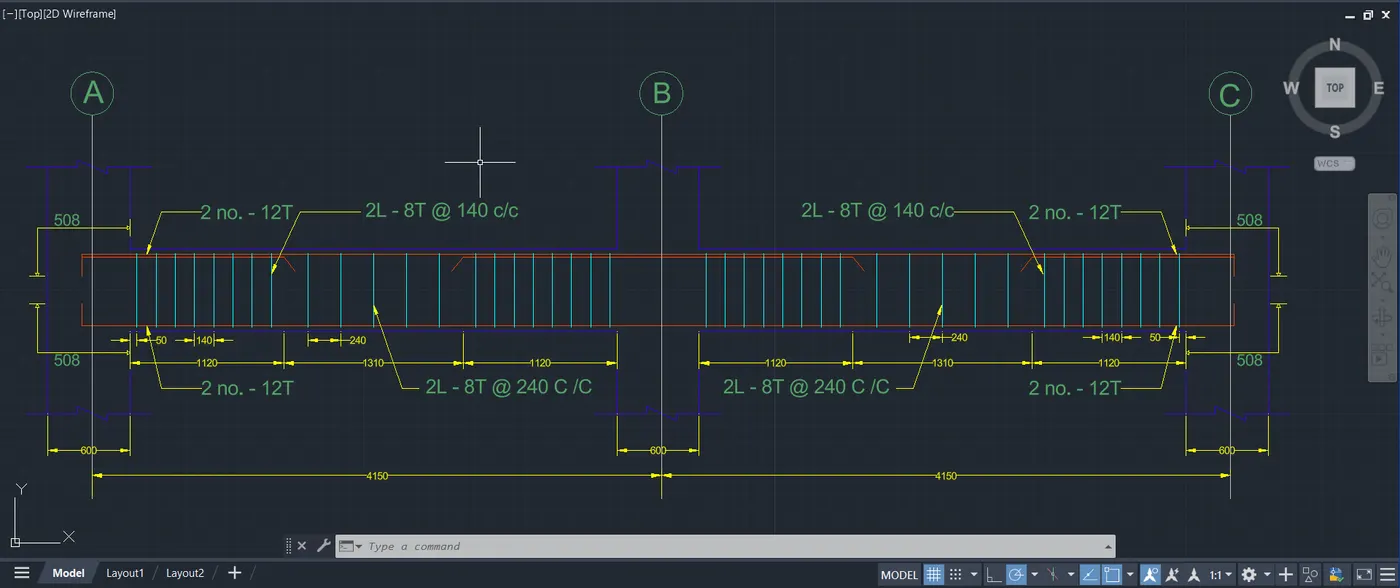
- Beam Elevation of two span beam along grid 7.
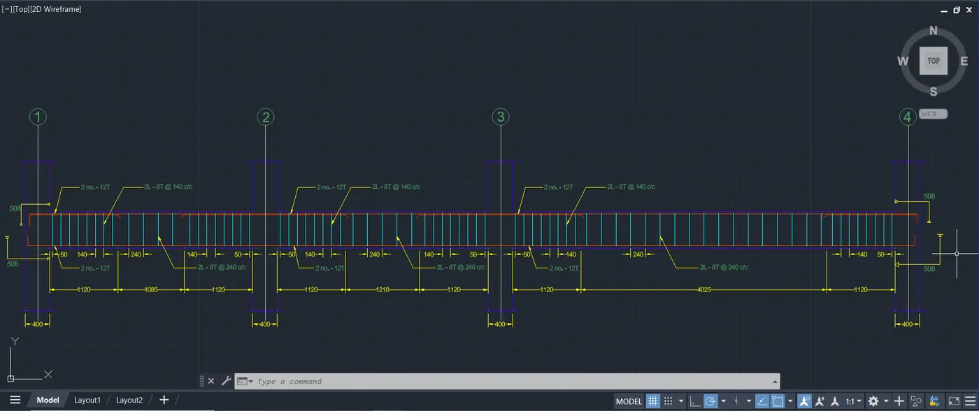
- Beam Elevation of three span beam along grid B.
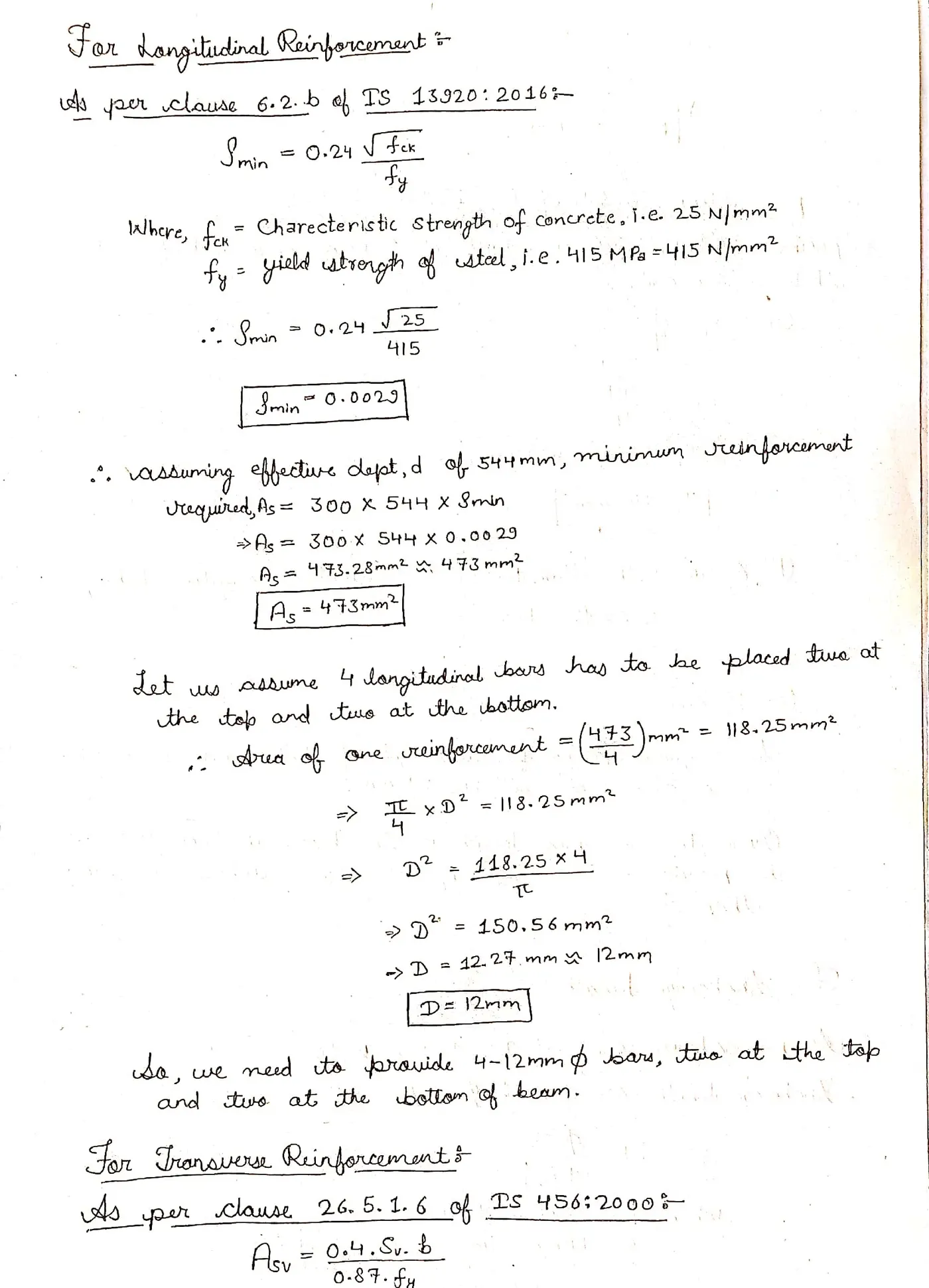
- The above-mentioned criteria for code is for regular beam design where as ETABS enhances its reinforcement details and other criteria to ensure the resistance for seismic behavior.
- As per IS 13920:2016 clause 2016.
- The sway shear force to right.
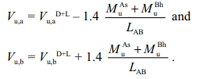
- MAs= 174kNm
- MBh=293kNm
- LAB=4.725m
- VD+L=92kN
- Vu,a=46kN
- Vu,b=230kN
- To sway shear force to left:
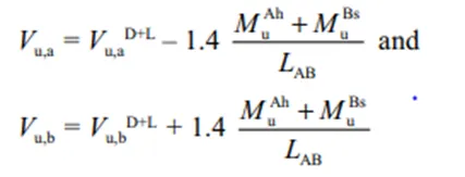
- MAh=234kNm
- MBs=155kNm
- LAB=4.725m
- VD+L=70kNm
- Vu,a=185kN
- Vu,b=45kN
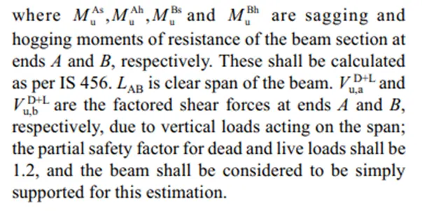
- As per the above formulated value, pick the higher value from Vu,a=185KN and Vu,b=230KN.
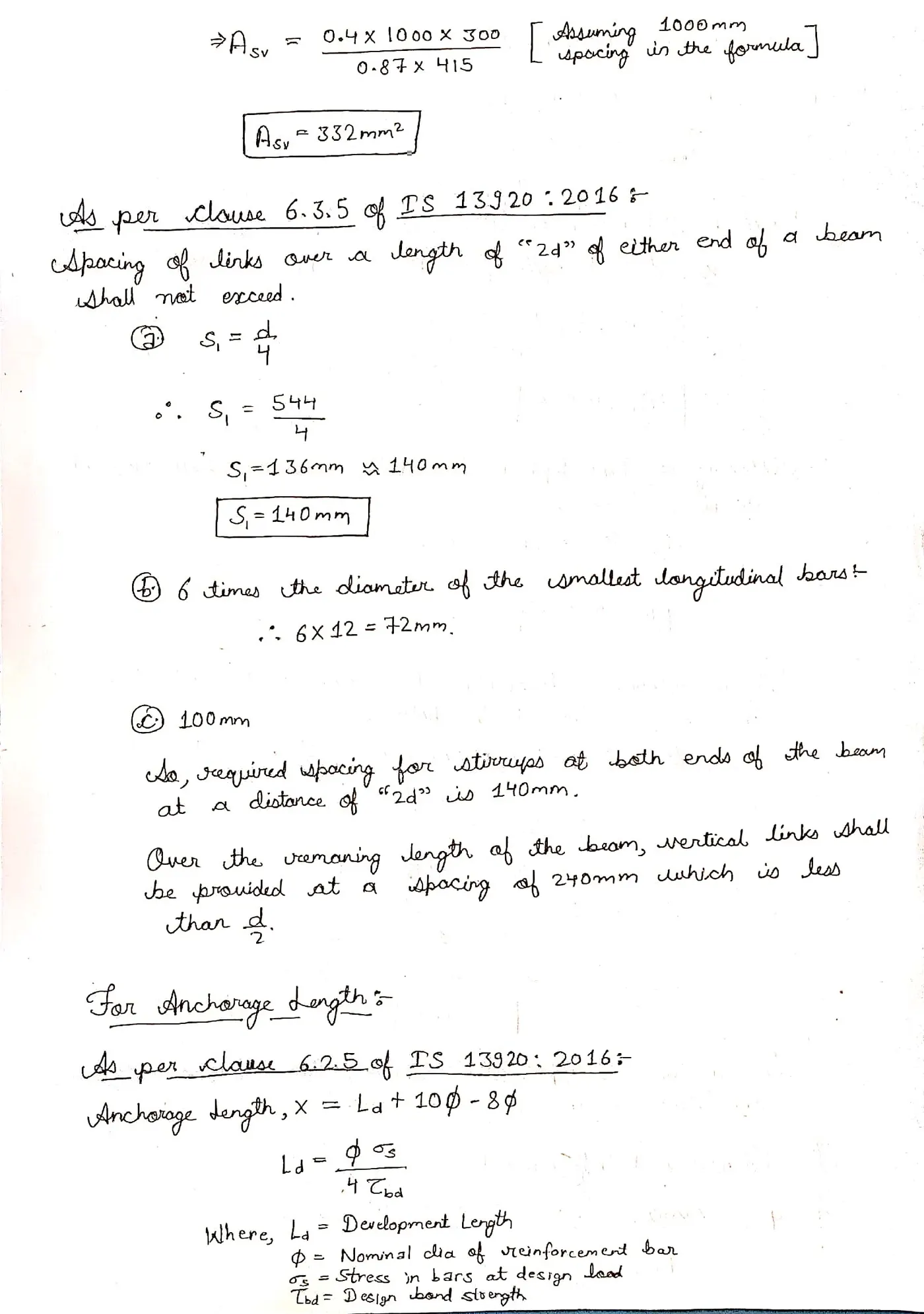
- So the minimum reinforcement for shear force resistance due to sway should be more than these value in the designed Beam, so that it can overcome different forces coming to it.
- But in my model the beams are already designed for maximum forces and does not fails so no new combinations are required.
- Existing shear capacity in the Beam:-
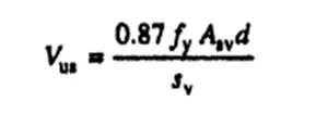
By the above formula,
Fy= 415 N/mm2.
ASV=332 mm2
d= 544 mm2
Sv= 140 mm
Vus=466 KN
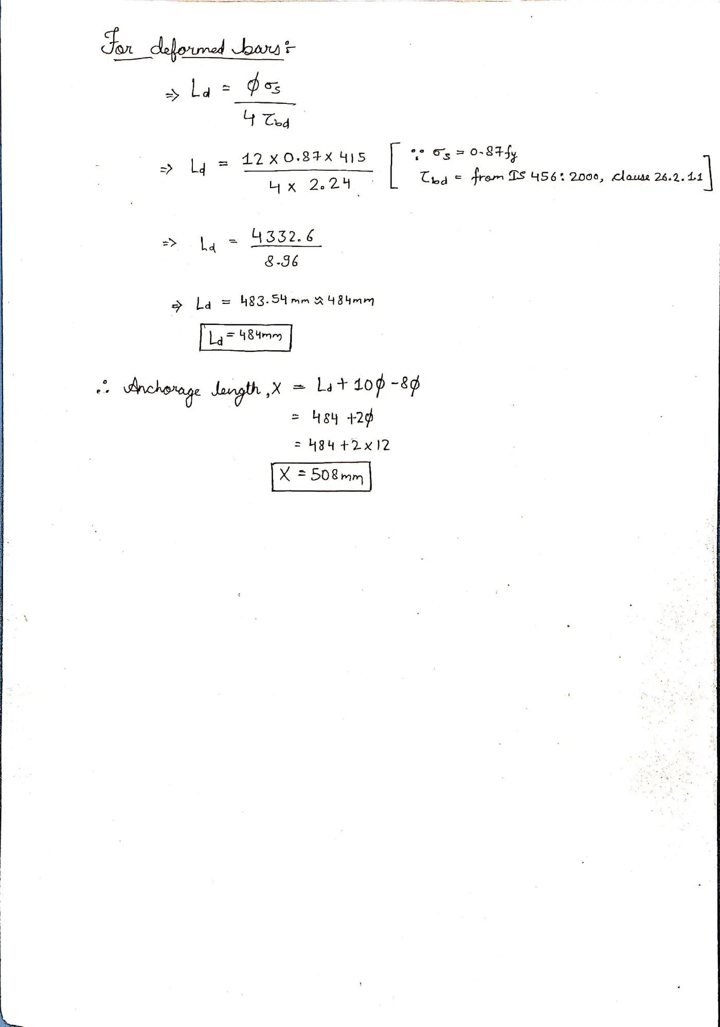
Hence shear rebar in drawing is okay as per IS 13920 code guidelines.
Result:-
The maximum requirement from the sway calculation is 230kN but the provided value is 466 kN. Hence it is safe.