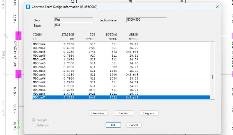
Reinforcement Detailing of Beams from ETABS output
Aim: Detail design of beams in Etabs provided in Challenge 7
The ETABS file for a G+4 building is provided. Run the analysis and design the RCC Moment ResistingFrame. The following challenge deals specifically with two continuous beams in the 1st floor.
1) 3 span continuous beam along grid A
2) 7 span continuous beam along grid 3
Address the following issues thereafter.
- Provide details of longitudinal and shear reinforcement for the two continuous beams. Sketch the beam elevation details or draft it using autocad software. A sample of how beam elevation details is prepared in consultancy firms is provided below. Participants can prepare it as per their preference:
- Provide reasons for failure of the middle span along grid A. What are the possible ways this issue can be resolved?
- Calculate value of the maximum shear force in any one of the spans in both the continuous beams, as per clause 6.3.3 (b) in IS 13920 – 2016. Also, confirm these values from shear force demand calculated by ETABS.Please note that if longitudinal reinforcement provided is more than required (as per ETABS results), the shear force demand will vary from what is provided by ETABS.
INTRODUCTION :
Detailing rule of any Reinforced concrete member:
1. Minimum reinforcement for shrinkage & temperature
2. Reinforcement required for limiting crack-width
3. Ultimate limit state design rebar requirement
4. Ductility rebar requirement
(Whichever is greater,Should be drawn in RC beam detailing)
- Minimum longitudinal reinforcement as per IS-13920-2016 clause 6.2.1 A = 360 mm2
- Minimum shear (or) transverse reinforcement as per IS-456-2000 clause 26.5.1.6 (Assuming 1000mm spacing in the formula) A = 332 mm2
- Development length as per IS-456-2000 clause 26.2.1 Ld = 41 x diameter of bar
PROCEDURE :
Step 1:
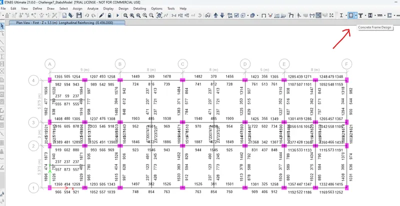
- After downloading the model given in the question, click the Concrete frame design tool in the ribbon tab.
- Choose Select design combinations
- Select the appropriate combination from the dialogue box
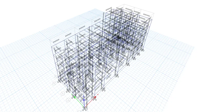
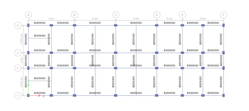
Step 2:
- Once the analysis is done, Click concrete frame icon
- It will starts checking the concrete design
- After the checking is done, go to the plan view
- On the plan view we have a column and beam detailing
- For this, Grid 3 and Grid A need to provide reinforcement details.
Step 3:
Grid 3B LONGITUDINAL REINFORCEMENT

At Top:
- Maximum Ast at Support = 194
- Maximum Ast at Middle = 485. [ 2 dia of 32mm = 1606 ; 1 dia of 25 mm = 490 ]
- To satisfy the support we need to provide 2 dia of 32mm bar and additionally in the middle need to provide 1 dia of 25mm.
At Bottom:
- Maximum Ast at Support = 1056
- Maximum Ast at Middle = 1501. [ 3 dia of 25mm = 1470 ; 1 dia of 16mm = 200.96 ]
- To satisfy the support we need to provide 3 dia of 25mm bar and additionally in the middle need to provide 1 dia of 16mm.
Step 5:
Grid A: LONGITUDINAL REINFORCEMENT
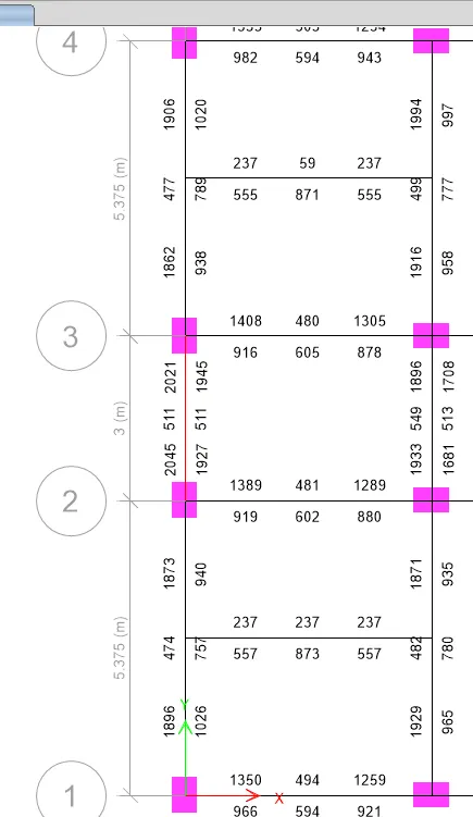
At Top:
- Maximum Ast at Support = 2045
- Maximum Ast at Middle = 477. [ 2 dia of 32mm = 1606 ; 1 dia of 25 mm = 490 ]
- To satisfy the support we need to provide 2 dia of 32mm bar and additionally need to provide 1 dia of 25mm.
At Bottom:
- Maximum Ast at Support = 1927
- Maximum Ast at Middle = 789 [ 2 dia of 32mm = 1606 ; 1 dia of 16mm = 200.96 ]
- To satisfy the support we need to provide 2 dia of 32mm bar and additionally in the middle need to provide 1 dia of 16mm.
Step 6:
- Right-Click the Grid A beam
- Click Details and switch it into shear details
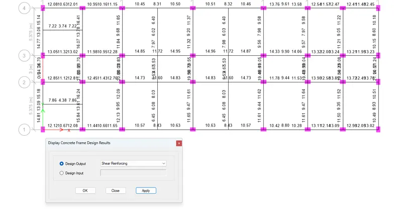

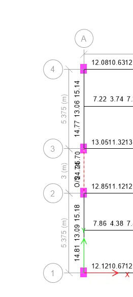
1) As per clause 6.3.3 the design force of equivalent Ve = 242.75 kN
2) Shear force under the linear analysis as per the load combination of UDCons66 = 194.825 kN
OR the Grade of concrete can be insceased to save the beam from O/S over stress