Reinforcement Detailing of Beams from ETABS output
Aim- To Run the analysis and design the RCC Moment ResistingFrame. The ETABS file for a G+4 building is provided.
Introduction- The ETABS file for a G+4 building is provided.
The following challenge deals specifically with two continuous beams in the 1st floor.
1) 3 span continuous beam along grid A
2) 7 span continuous beam along grid 3
Procedure-
-Open attached file in ETABS
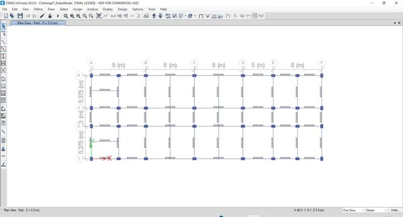
-Now Run Analysis
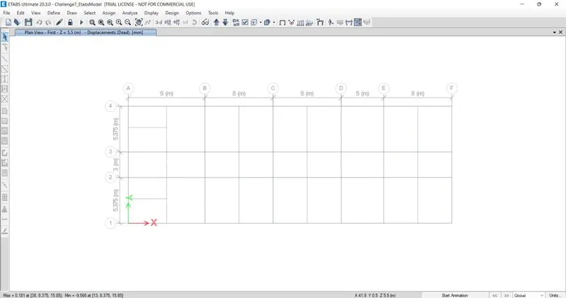
-Select concrete frame design and sysytem design the frame
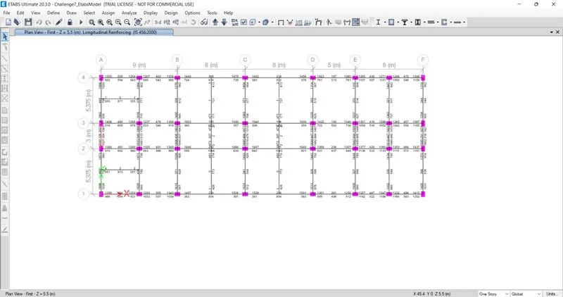
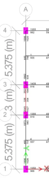
-Go to concrete frame design>Select display design info>Select total longitudinal reinforcement>ok
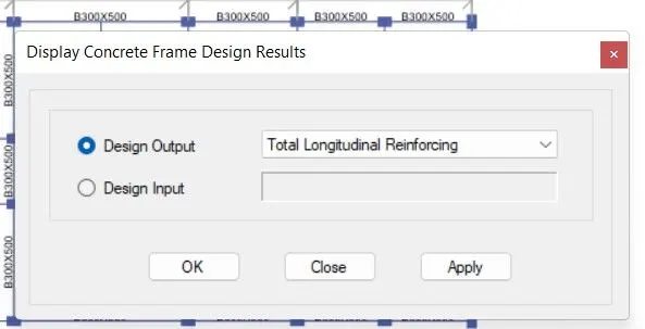

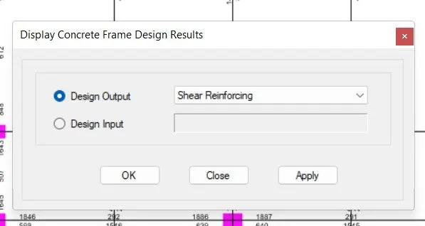
-Go to concrete frame design>Select display design info>Select shearreinforcement>ok


- Reasons for failure of the middle span along grid A.
The mid span is failed because of over stress in the beam. The shear steel was not calculated for this beam,
Shear stress due to shear force and torsion together exceeds maximum allowed.
Design shear stress exceeds the shear capacity of the scetion.
-Add sway combination
-GO to Define>Load combination>Add new>Add load as per follow
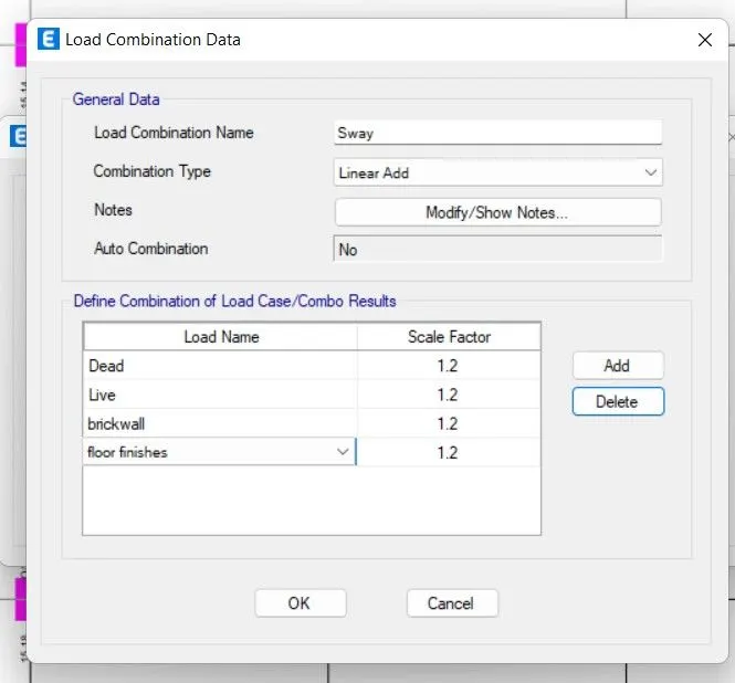
-Now assign this load
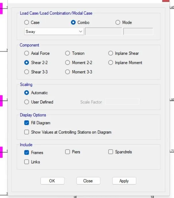
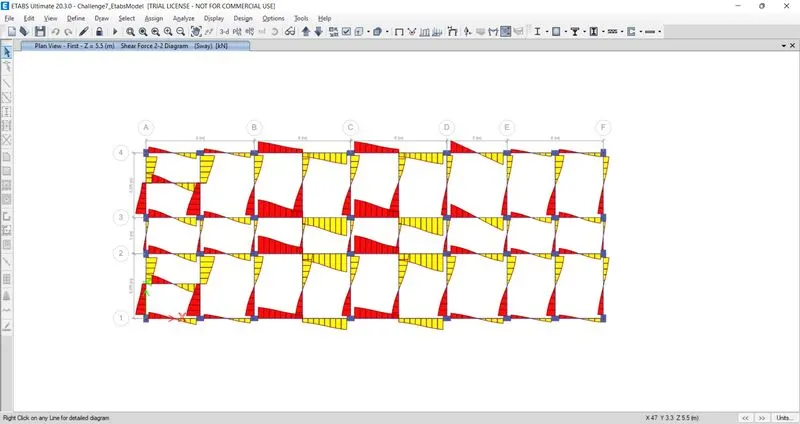
Sway shear force to Right
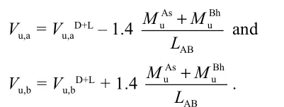
`M_(as)` = 133.35 kN-m
`M_(bh)` = 205 kN-m
`V_(d+l)`= 93 kN
L = 7.675m
`V_(u,a)`= 31.28 kN
`V_(u,b)`= 154 kN
Sway shear force to Left
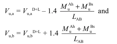
`M_(as)` = 205 kN-m
`M_(bh)` = 133.35 kN-m
`V_(d+l)`= 93.86 kN
L = 7.675m
`V_(u,a)`= 154 kN
`V_(u,b)`= 31.28 kN
Existing Shear Capacity in Beam as per IS 456 Clause 40.4
`V_(us) = (0.87*f_y*A_(sv)*d)/s_v`
fy = 415 N/mm2
Sv = 125mm
d = 445mm
Asv = 156 mm2
`V_(us)`= 200kN
Hence Shear Rebar in drawing as per 13920-2016 code guideline is OKAY
Result-
We run the analysis and designed the RCC Moment ResistingFrame.
Provided details of longitudinal and shear reinforcement for the two continuous beams.
Provided reasons for failure of the middle span along grid A and the possible ways this issue can be resolved.
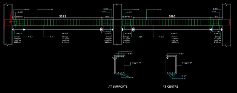
- Longitudinal Reinforcement
- Shear Reinforcement