Reinforcement Detailing of Beams from ETABS output
Aim & Introduction :
The ETABS file for a G+4 building is provided. Run the analysis and design the RCC Moment ResistingFrame. The following challenge deals specifically with two continuous beams in the 1st floor.
1A) 1) 3 span continuous beam along grid A
2) 7 span continuous beam along grid 3
Address the following issues thereafter.
• Provide details of longitudinal and shear reinforcement for the two continuous beams. Sketch the beam elevation details or draft it using autocad software. A sample of how beam elevation details is prepared in consultancy firms is provided below.
Procedure :
1A)
- Open The attachement from the Page
- Download the software
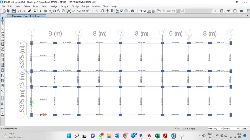
- As soon as the Display Appears,Check whether the plan is based on base floor will appear as follows.
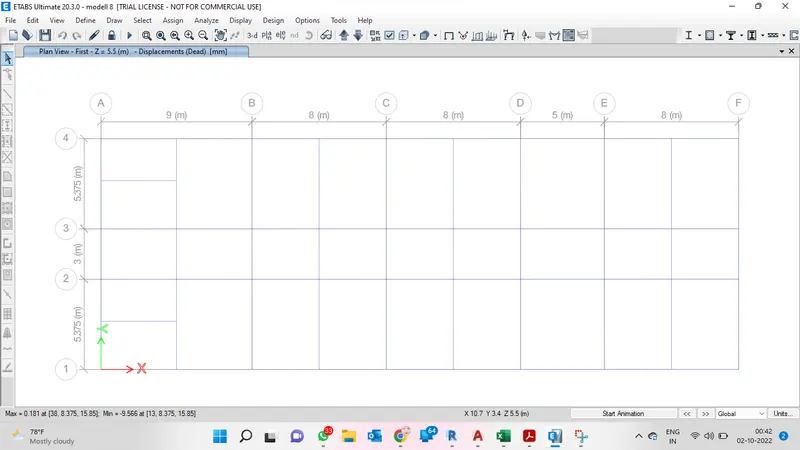
- Run the File using analyze tool and max and min deflection will appear at the bottom of table as shown
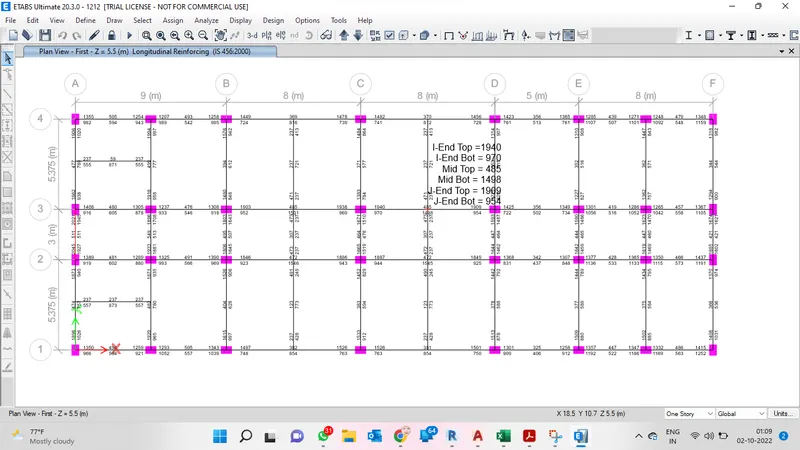
- 1) 3 span continuous beam along grid A
- Choose the Concrete frame icon from the tool bar and check the design or Simply provide shift+F6 to analyze the Longitunial Reinforcement of the frame as shown below and choose display section and change it from longitunial reinfocement to shear reinforcement as show below
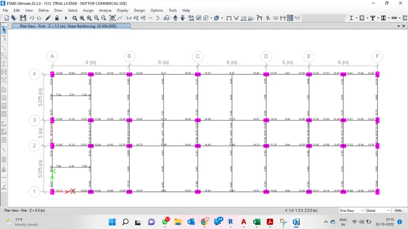
- 7 span continuous beam along grid 3
- Choose the Concrete frame icon from the tool bar and check the design or Simply provide shift+F6 to analyze the Longitunial Reinforcement of the frame as shown below and choose display section and change it from longitunial reinfocement to shear reinforcement as show below
2A)
Provide reasons for failure of the middle span along grid A. What are the possible ways this issue can be resolved?
- From the Above result we come to know the failure in A Grid beam
- The mentioned OS is Over Stressed at the midspan along grid A
- This can be Checked in the Analyzis Diagram Itselt
- the values can be checked by selecting the options and getting the details as shown below
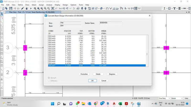
- From this box we may able to know its equal to allowable load or whether it is safe or failure ,for our case it has been displayed below\
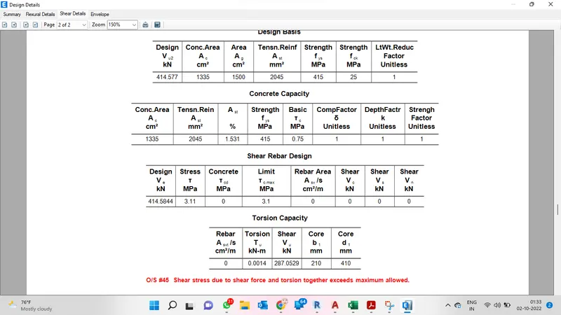
- From this we can understand that beam at midspan fails and it can be reolved by
- Either by Increasing or reducing the load that is subjected to the frame
- By Increasing the shear capacity of building the failure gets reduced,it can be done by increasing the grade of concrete it can be minimized.
3A)
Calculate value of the maximum shear force in any one of the spans in both the continuous beams, as per clause 6.3.3 (b) in IS 13920 – 2016. Also, confirm these values from shear force demand calculated by ETABS.Please note that if longitudinal reinforcement provided is more than required (
- As per IS 13920-2016
Sway shear Force to Right Sway Shear force to Left
Mas = 174KNm Mah = 234KNm
Mbh = 293KNm Mbs = 155Knm
Lab = 4.725m Lab = 4.725m
Vd+l = 92KN vd+l = 60KNm
Vu,a = 46KNm Vu,a = 185KNm
Vub = 230KNm Vub = 45KNm
Exixsting Shear Capacity in beam as per drawing (as per Is 456-2000)
Vus = .87fyAsd/Sv
fy = 415N/mm2
As = 151mm2
d = 450mm
Sv = 100mm
Vus = 245Knm
Shear Rebar drawing is Ok As per IS 13920 and it is Satisfactory
RESULT : From the above question we are able to know the shear and longitudinal reinforcement values.and also shear detail values whether it fails or not and from the detail we can get to know the base shear value.