Reinforcement Detailing of Beams from ETABS output
Aim:
To carryout analysis of the given Etabs model and to design the RCC moment resisting frame, to provide the detailing of longitudinal and shear reinforcement for two continuous beams and also to provide the reasons of failure of middle span along grid A.
Introduction:
- In this challenge two beam detailings are done:
1) 3 span continuous beam along grid A.
2) 7 span continuous beam along grid 3.
- Now, inorder to calculate the maximum shear force in any of the spans of the continuous beam, IS13920-2016, clause 6.3.3 (b) is followed which states that
Shear force capacity of a beam shall be more than larger of,
a) Factored shear force as per linear structural analysis
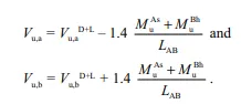
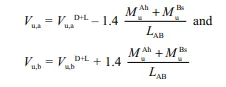
b) Factored gravity shear force plus equilibrium shear force plastic hinges are formed at both the ends of the beam given by:
1. If sway is to right:
2. If sway is to left:
Procedure:
- Open the Etabs model given in the question.
- Then go to analysis and check the given model.
- Carry out the analysis of the model by choosing Run analysis option from the analysis option again.
- Go to concrete frame design drop down after completion of analysis and carry out the design of the beam by choosing start design/ check option.
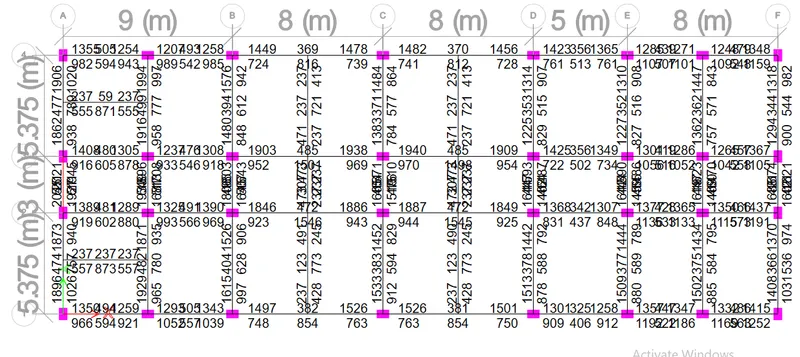
- We obtain reinforcement values from display design info option in Concrete frame design dropdown.
- Carry out the detailing of grid A and grid 3 beams.
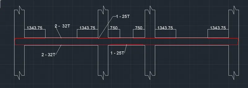
- Detailing of grid A:
- Maximum value of reinforcement at the top is 2045 `mm^2` and at bottom is 1945 `mm^2`.
- Hence, provide 2 no.s of 32mm dia bars at top and bottom i.e 1608 `mm^2`
- Then, we have to provide additional one 25mm dia bar to satisfy the remaining area.
- Cover provided here is 30mm.
- Shear reinforcement provided is 10mm dia bars @ 50mm c/c throughout the beam.
- Now, detailing is carried out for grid 3:
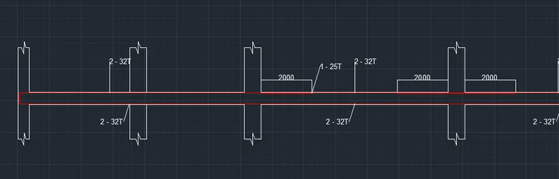
- The maximum value of reinforcement at top is 1940 `mm^2` and at bottom is 1501 `mm^2`
- Hence, provide 2 no.s of 32mm dia bars at top and bottom i.e 1608 `mm^2`
- Then, we have to provide additional one 25mm dia bar to satisfy the remaining area.
- Cover provided here is 30mm.
- Shear reinforcement is provided as 10mm dia bars @ 100mm c/c throughout the beam.
- Beam detailing is completed as such.
- Possible reasons for failure of the middle span along grid A are mentioned below.
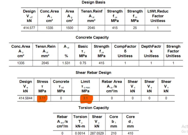
- From the above results it is clear that, failure is due to high shear stress.
- Here the shear stress developed is 3.11MPa which is greater than the allowable shear stress i.e, 3.1MPa which leads to the failure of this beam.
Possible ways by which this failure can be resolved are:
- Using higher grade of concrete so that the permissible stresses are increased in it .
- Also, the shear strength of the beam can be increased by reducing the effective depth of this beam.
For grid A:
sway to right
Hogging moment of resistance = 173.974 kN m
Sagging moment of resistance = 292.99 kN m
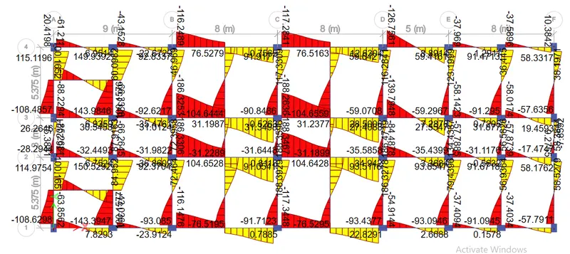
Factored shear force due to vertical loads acting on the span ,Vu,bD+L=114.9754kN
Clear span, LAB= 4.725m
So as per IS 13920, sway shear is calculated as:
Vu,b= 253.32kN for sway to right
Now, for sway to left the sway shear is calculated as:
Vu,b= 252.43kN for sway to left.
Shear force demand calculated from etabs is: 237.54 kN
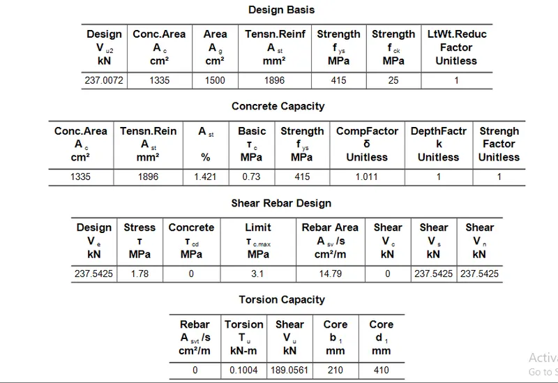
- Here, take the shear sway to be 253 kN.
Grid 3:
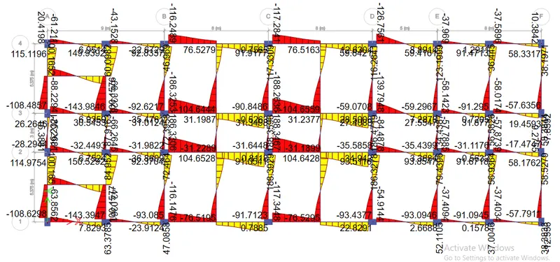
Sway to right
Hogging moment of resistance = 161.07 kN m
Sagging moment of resistance = 219.39 kN m
Factored shear force due to vertical loads acting on the span ,Vu,bD+L= 88.23 kN
Clear span, LAB= 3.95 m
So as per IS 13920 sway shear is calculated as:
Vu,b= 240.4 kN for sway to right
Now, for sway to left the sway shear is calculated as:
Vu,b= 243.386 kN for sway to left.
Shear force demand calculated from etabs is : 209.552kN
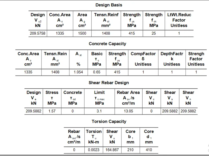
- Hence take the shear sway as 240 kN.
Result :
Hence, the entire detailing and designing of the beam is carried out as per the IS 13920 -2016.