Reinforcement Detailing of Beams from ETABS output
1. Aim: To design the longitudinal reinforcement and shear reinforcement of the two beams in the building and to identify the shear force in the continuous beams and to identify the variation of the reinforcement provided from what the E tabs is provided.
Procedure:
- Every beam should be provided with the reinforcement in the tension zone and as well as in the compression zone if required based on the load applied
- The reinforcement provided should be with stand the load and should not develop any cracks in the surface of the beam and the deflection of the beam should be with in the limits.
- The shear reinforcement should not be less than the minimum requirement from the IS 456:2000 cl 26.5.1.6
`Aunderset(sv)`=(0.4b`Sundersetv`)/(0.87`fundersety`)
The Spacing between the stirrups is 1000mm then the area of the shear reinforcement is 332`mmoverset2``
- Click on the attachment of the challenge and the building model is opened now click on the analysis option in the ribbon bar and the building is saved with the appropriate file name and the analysis is performed in the Etabs and the reinforcement for the each span of the beams is found in the software itself.
- The beams or the structural members are analysed and to view the values on the window click on the concrete frame design option in the ribbon and the reinforcement details are displayed on the window of the Etabs.
- After the analysing the main reinforcement the shear reinforcement is to be analysed, the shear reinforcement is analysed by changing the concrete frame design to the shear reinforcing option.
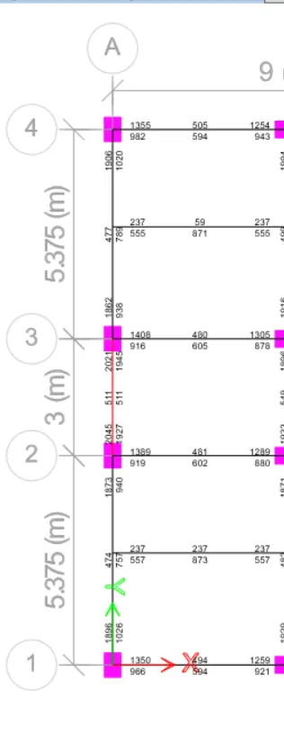
Longitudinal reinforcement in the Grid direction A.

Longitudinal reinforcement in the 7 beams in the grid direction 3
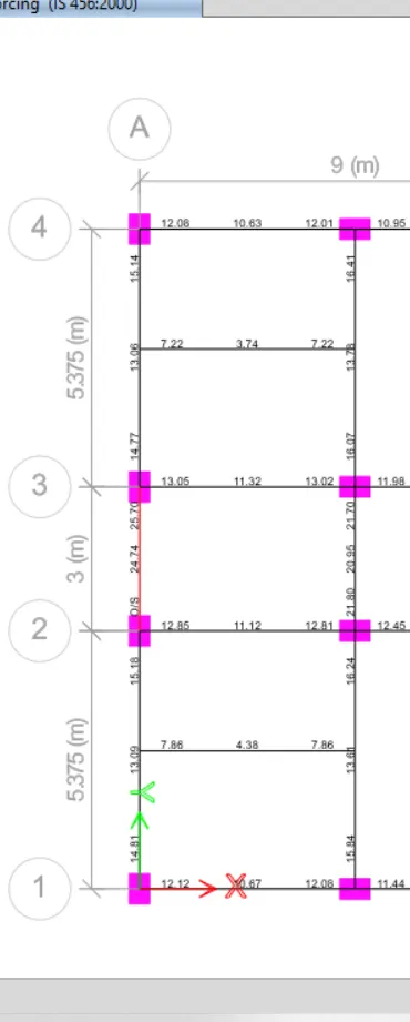
Shear reinforcement in the grid direction A.

Shear reinforcement in the 7beam in the grid direction 3.
- we can notice that the one of the beam is failed due to over stress caused by the load and the reinforcement is not displayed in the window.
- Click on thebeam and it will open the concrete beam design information and it will show the beam details where the load actions combnations is failed.Generally the failure occurs due to the exceeding limits of the loads.
- Click on the details of the beam and it will display the all the details of the beam like sectional properties,material properties,code parameters like factor of safety etc. In this the general parameters may be in different units like the area must be in `cmoverset2`and that should be carefully observed with out any confusion.
- In the 3 span beam one of the span is failed due to shear stress and this is failure can be over come by the increase or decrease of the load over the beam.
- Due to the earthquake forces the building will sway either right or left due to the vibration created by the building load.The building is to be with stand the force created by the vibration of the load.
- The shear force created by the seismic vibration of the building is
sway shear to the right is `Vunderset(ua)`=`Vunderset(ua)overset(D+L)`-(1.4(`Mundersetuoverset(as)`+`Mundersetuoverset(bh)`/(`Lunderset(AB)`
`Vunderset(ub)`=`Vunderset(ub)overset(D+L)`-(1.4(`Mundersetuoverset(as)`+`Mundersetuoverset(bh)`/(`Lunderset(AB)`
sway shear to the left is `Vunderset(ua)`=`Vunderset(ua)overset(D+L)`-(1.4(`Mundersetuoverset(ah)`+`Mundersetuoverset(bs)`/(`Lunderset(AB)`
`Vunderset(ub)`=`Vunderset(ub)overset(D+L)`-(1.4(`Mundersetuoverset(ah)`+`Mundersetuoverset(bs)`/(`Lunderset(AB)`
The sagging and the hogging moment and the span of the beams can be found from the Etabs software..
- The load combination i.e combination of the dead and live load is not considered then we need to add the combination of the load and to find the shear force of the beam.
- Then the shear force due to the right and left sway shear of the building is arrived from the above equations and the reinforcement we provide for the beam should with stand the shear force caused in the beam.
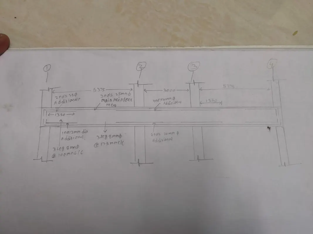
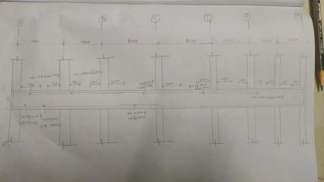
- The reinforcement can be plotted and submitted to the client using the Auto cad or any other software but auto cad is the most relavant software which is used in the design course.
- The area of the reinforcement is which is to be provided in the beam is known as the 'Demand' of the reinforcement and the reinforcement is not available in the same required quantity so we need to arrange the reinforcement in the available diameters on the market i.e 8mm,10mm,12mm,16mm,20mm,25mm etc and the generally the main bars are provided from the 12mm diameter and the shear reinforcement is provided by the 8mm diameter and the reinforcement we provide is generally slighltly larger than the requirement and this is called the capacity of the reinforcement.
- In the 3 span the 25mm diameter bar is used for the main reinforcement and in the 7span beam also 20mm and 25mm bars used for themain reinforcement and the shear reinforcement is provided by the 8mm diameter bar and spacing for the shear reinforcement is 100mm at the supports and its varies from the 125mm to the 175mm at the centre of the beam.
- The Additional reinforcement is provided to a specific length 1350mm or 2000mm or 1000mm at the supports.
- After the plotting of the reinforcemnt we can submit the drawing to the client for the approval.
- The sway action or any other load action of the building due to the force is viewed in the Etabs software by using the force diagram option.
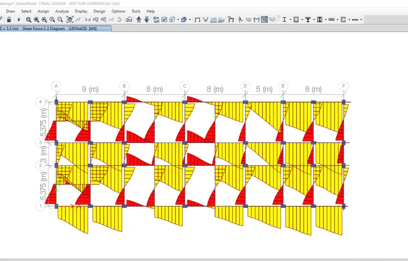
- Finally from the code IS 456:2000 cl40.4 we can conclude the shear force can be concluded and it should be greater than the all the forces arived due to the sway action and other load combinatons on the building.
`Vunderset(us)`=(0.87`fundersetyAunderset(sv)d`)/`sundersetv`