Reinforcement Detailing of Beams from ETABS output
Detail design of beams in Etabs 2018.
The ETABS file for a G+4 building is provided. Run the analysis and design the RCC Moment ResistingFrame. The following challenge deals specifically with two continuous beams in the 1st floor.
1) 3 span continuous beam along grid A
2) 7 span continuous beam along grid 3
Address the following issues thereafter.
• Provide details of longitudinal and shear reinforcement for the two continuous beams. Sketch the beam elevation details or draft it using autocad software. A sample of how beam elevation details is prepared in consultancy firms is provided below. Participants can prepare it as per their preference:
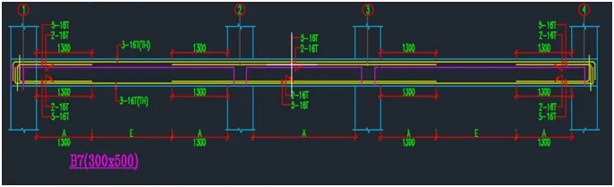
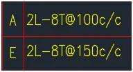
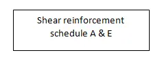
• Calculate value of the maximum shear force in any one of the spans in both the continuous beams, as per clause 6.3.3 (b) in IS 13920 – 2016. Also, confirm these values from shear force demand calculated by ETABS.Please note that if longitudinal reinforcement provided is more than required (as per ETABS results), the shear force demand will vary from what is provided by ETABS.
Aim:
To use Given file and run the analysis. Then adrress the changes accordingly. provide the reason for the falure and ways to reslove.
Procedure:
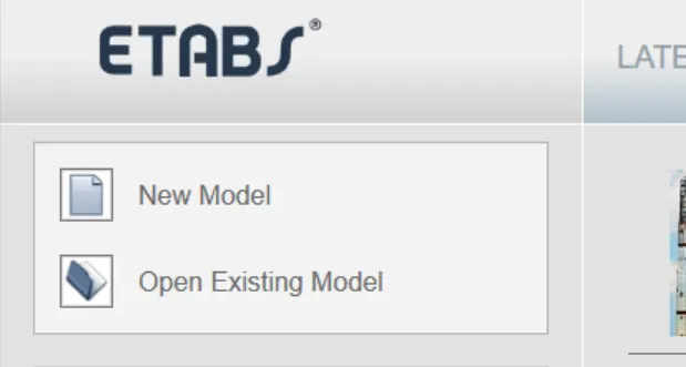
First we need to open the model by click on the open existing model.
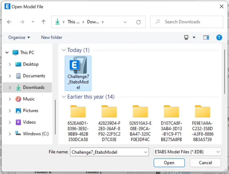
Now select the file and click open.
now file will be opened then click on the plan option in the home tab.
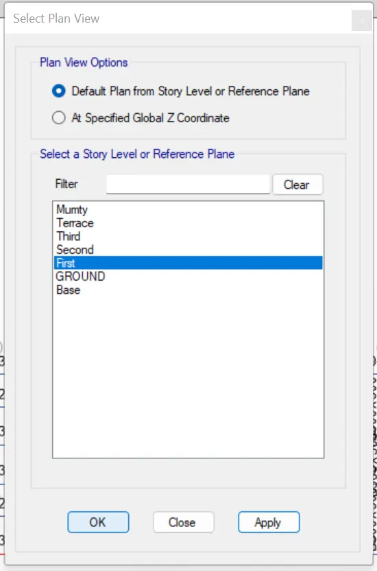
Then click on the first floor and then apply and ok.
Now click on run analysis on the home tab.
we can see the design is running.
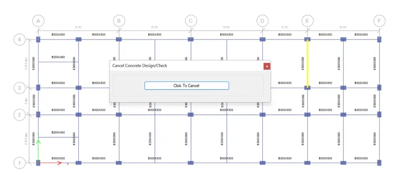
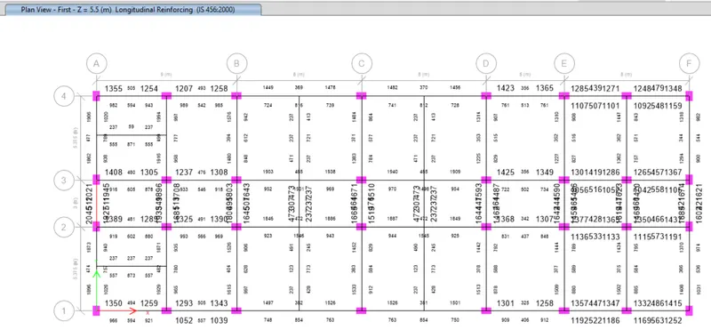
As default we can see the longitudinal reinforcement once the check has completed.
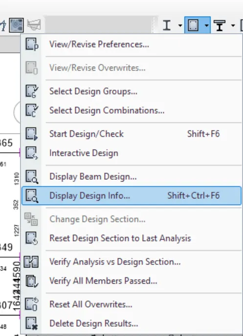
To get a shear reinforcement we need to click on the doen arrow beside concrete design icon.
Then click on the design display info.
Now select the shear reinforcement in the tab and click ok.
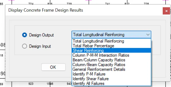
Now we can see the shear reinforcement.
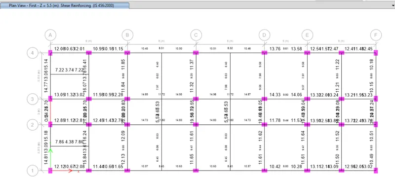
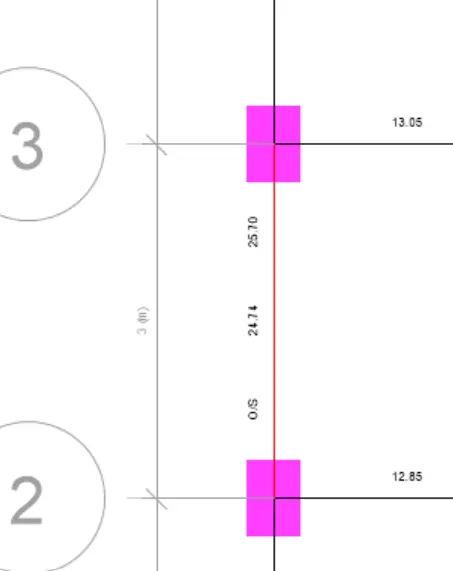
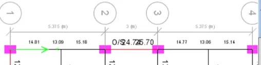
• Provide reasons for failure of the middle span along grid A. What are the possible ways this issue can be resolved?
It says that O/S that means the beam is over stressed.
once right click on the beam we can see the tab appear in which we can see shear steel is not calculated for the 3 combinations.
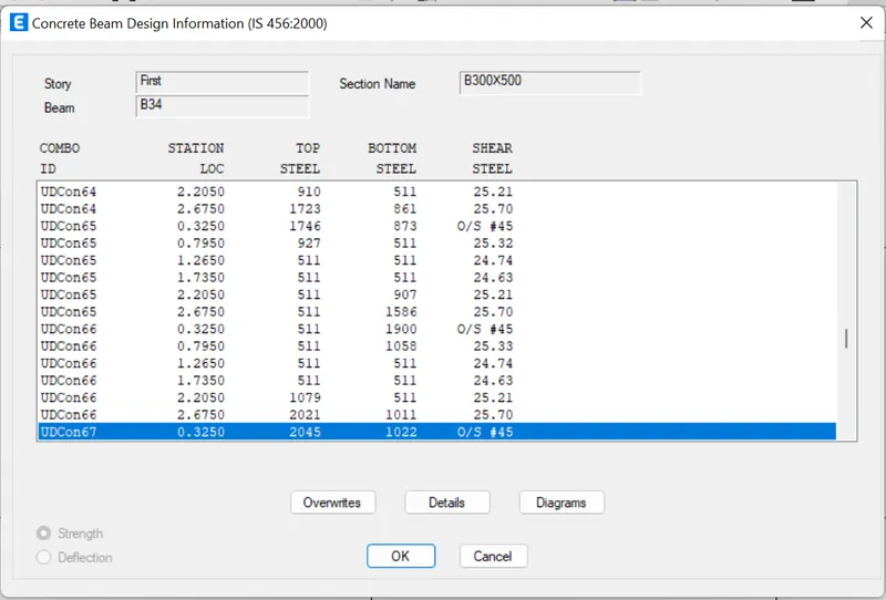
now select one of the combination and then click on the details below.
Now we can see the design details for the following.
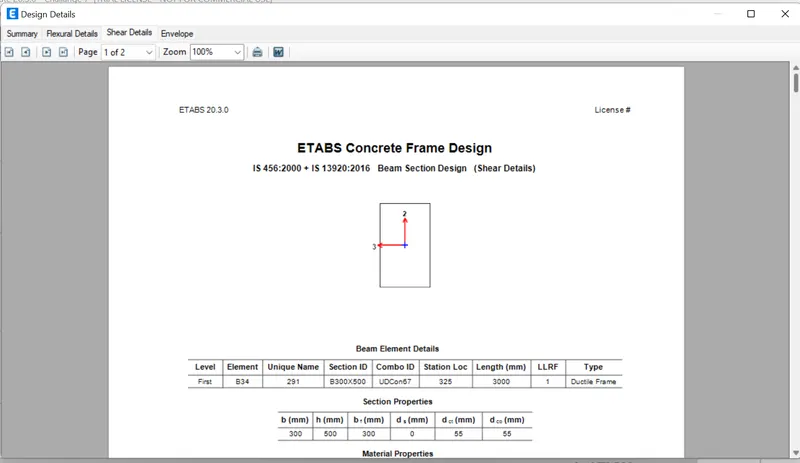
NOw click on the shear details in the ribbon bar to see the shear details.
Reason for failure:
In the bottow of the sheat we can notice why it is failed.
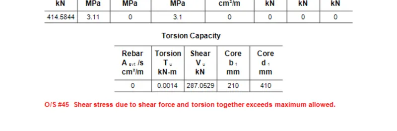
as it says shear force is incerased and the torsion is very less as we can see in the details.
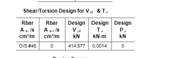
Suggestions to fix:
- We need to reduce the loading or increase the loading.
- The shear capacity of the concrete can be varies according to the grade of concrete. as we used M25 for the entire building for this one beam we incerease the grade. Then we can Increase shear capacity of the beam. It pass the shear stress design
Now the detailing:
shear reinforcement for the 3span
Shear reinforcemt along 7span
Longitudianl reinforcemet along 3span
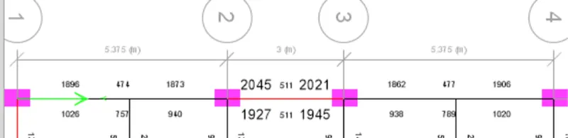
Longitudianal reinforcement along 7span.

Apart from the detailing and the normal detailing we should satisfy ductility requirement according to the IS13920-2016
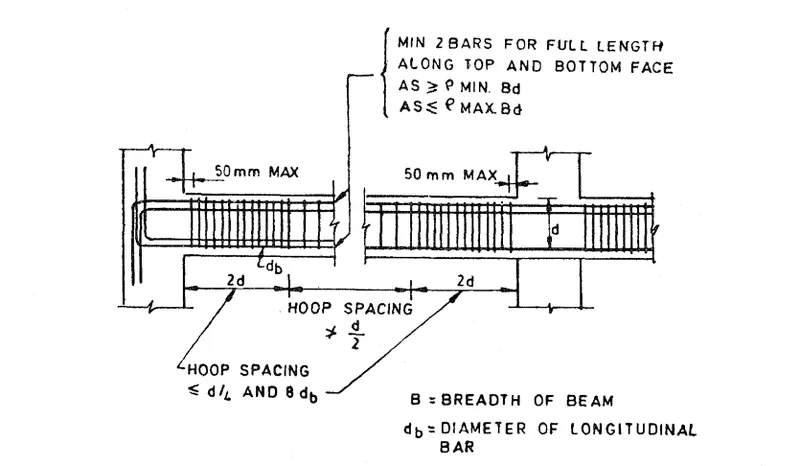
From the clause we can identify that for the length of 2D we should keep a certain shear reinforcement spacing with the conditions.
In the middel of the soan shear reinforcement should not be more than d/2. where d= effective depth of beam.
Additional check as per the asked to check wheather the provided reinforcement in the beam is satisfyed sway shear.
As per IS13920-2016 clauses 6.3.3(b):
We should check the sway shear demand for the two following cases for which reinforcement should satisfy.
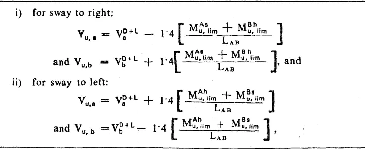
where

we can get the values of the momemts from the table in the etabs model and bring them and substitute in the eqation we get.
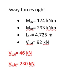
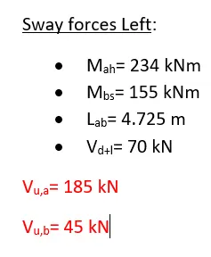
The shear reinforcement should satisfy the greater the both Vu,a. so the shear should be more than 185kN to meat the sway requirement.
The greater value between two sway of Vu,b should statisfy that 230kN.
3span continues along A:
As in the we can see the reinforcement we used alaong the three span direction. in the middel span we can not follow the guidlines per the code book becouse of the length.
As we check the rcc reinforcement drawing along grid A we can see we are not followed sample given in the challange and followed own standerd.
In the bottom support we must provide 100mm supports at all the suppor. In the middel of the span as the span.
Provodong the additional reinforcement in the support top and the support bottom
7span continues beam along grid B:
providing the additional reinforcement apart from the etabs design result.
extension of the additional reinforcement can be taken as l/4.
The design requirement from the etabs must shows the large amount but we cannot provide exact amount like that becouse due to commercial products available demant and the capacity of the reinforcement.
To avail the extra combination to arrive dead load sway shear:
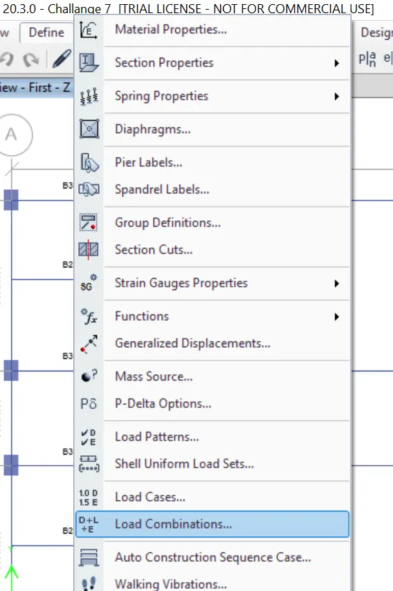
First click on the define in the home tab and then click on the load combination.
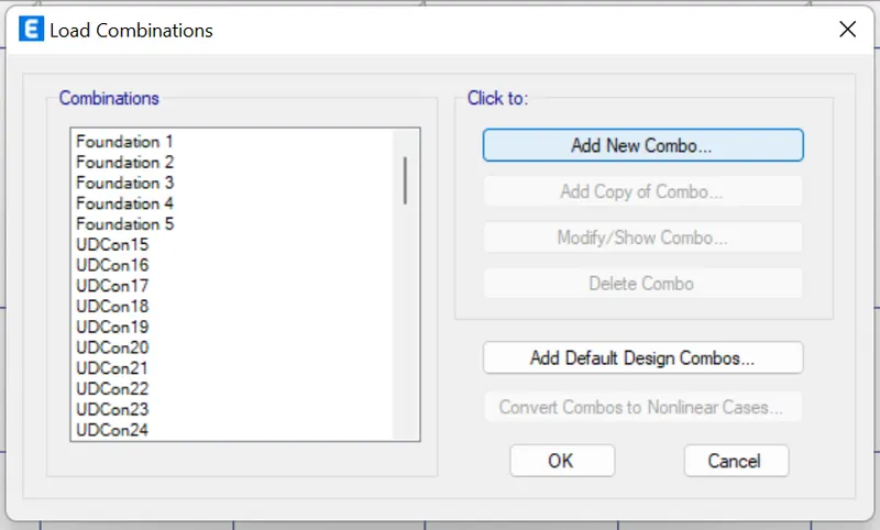
now click on the add new combo
by clicking on the add and then changing the deatails add the combo.
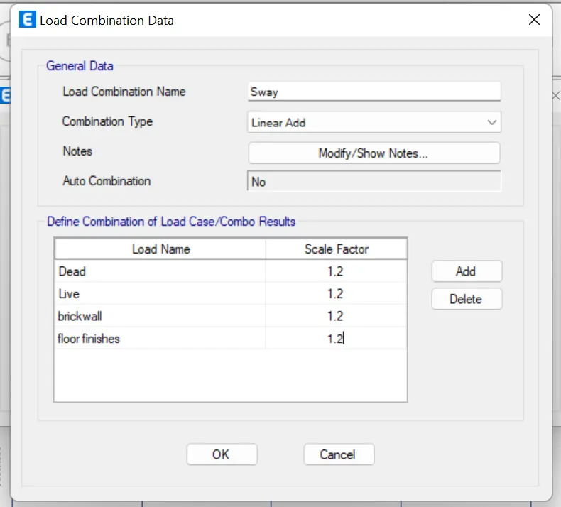
Now click on Ok.
for this combination we can see the shear force combination.
now click on the member force diagram in the home tab.
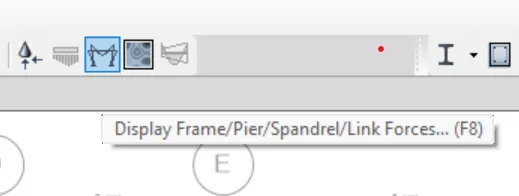
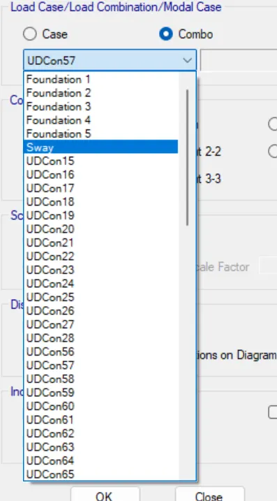
now select the sway in the case.
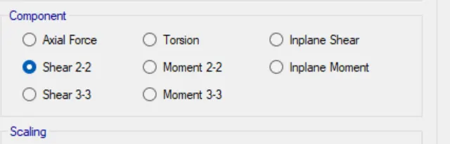
Now select the shear 2-2
Then click on apply and then OK.
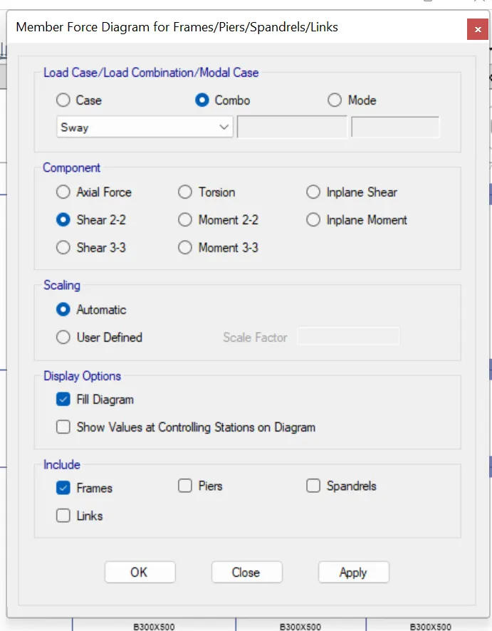
we can get d+l shear foce.
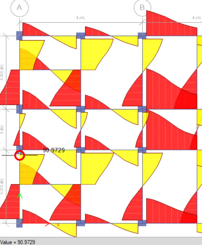
Now we are going to check the provided reinforcemnt of the drawing satisfy the sway shear requirement.
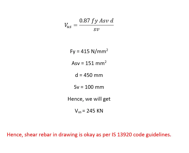
The existing shear capacity as per the drawing
(as per IS 456-2002 cluses 40.4)