Reinforcement Detailing of Beams from ETABS output
The ETABS file for a G+4 building is provided. Run the analysis and design the RCC Moment ResistingFrame. The following challenge deals specifically with two continuous beams in the 1st floor.
1) 3 span continuous beam along grid A
2) 7 span continuous beam along grid 3.
ANS:
AIM:
- To carryout the analysis of the given Etabs model and to design the RCC moment resisting frame.
- To provide the detailing of longitudinal and shear reinforcement for two continuous beams.
- To provide the reasons of failure of middle span along grid A.
Introdution:
- In this challange two beam detailing is done.
- 3 span continous beam along the grid 3.
- 7 span continous beam along the grid 3.
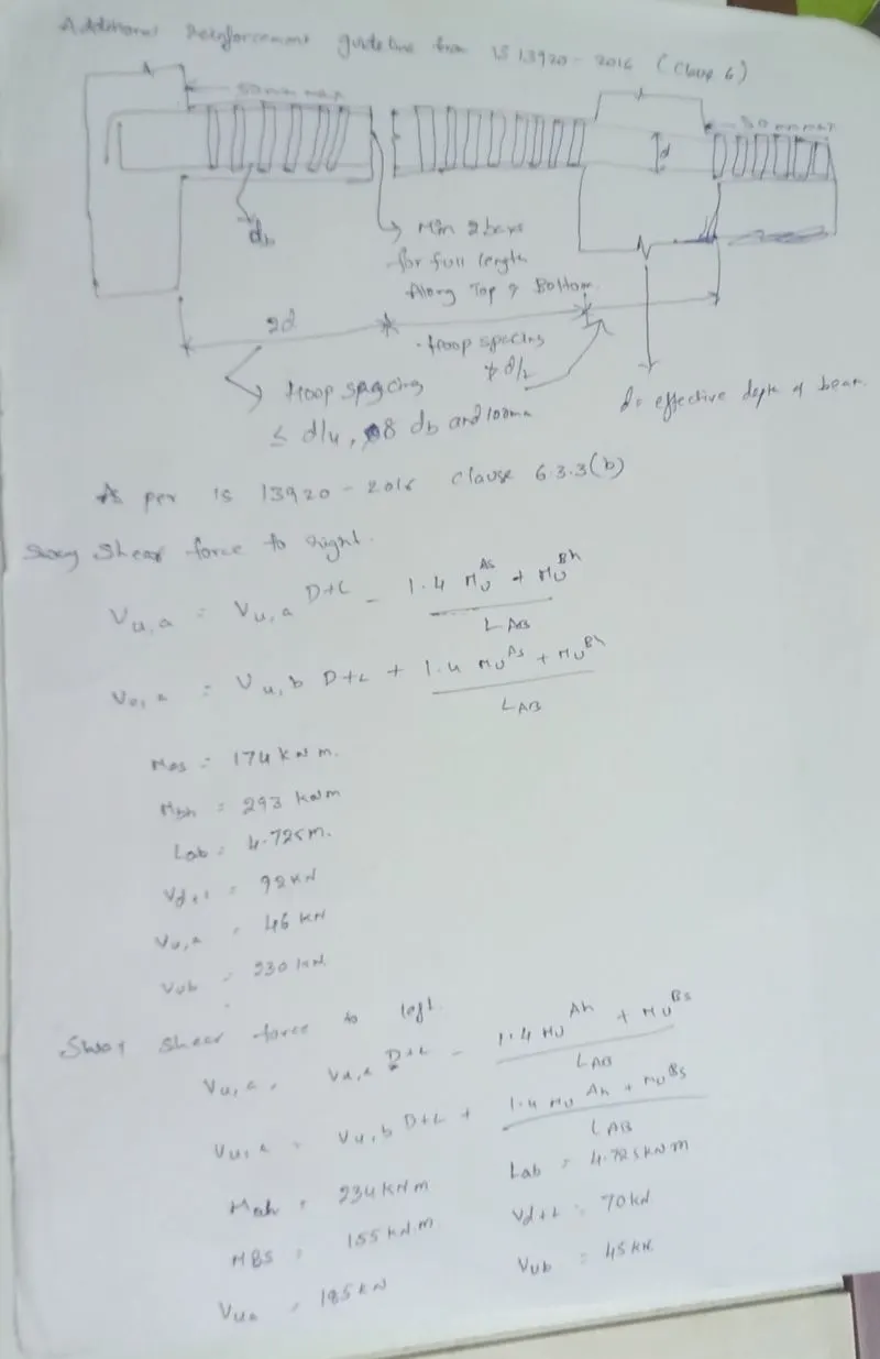
Then inorder to calculate the maximum shear force in any of the spans of the continuous beam, IS13920-2016, clause 6.3.3 (b) is followed which states that.
shear force capacity of a beam shall be more than larger of,
- Factor shear force as per linear structural analysis.
- Factor gravity shear force plus equilibrium shear force plastic hinge are formed at both ends of the beam.
Procedure:
Download the attachement given in challanges.
open E-TABS software.
open the download file.
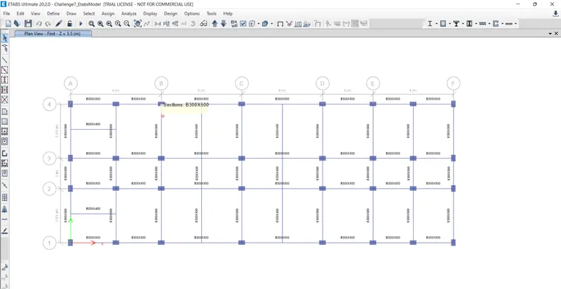
- After that again go to analysis and carry out the analysis of the model by choosing Run analysis option.
- After analysis have been completed go to concrete frame design drop down and carry out the design of the beam by choosing start design/ check option.
- After completion, reinforcement values are obtained from display design info option in Concrete frame design dropdown.
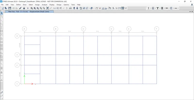
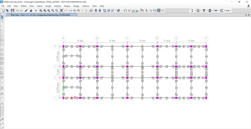
- Now, we need to carry out the detailing of grid A and grid 3 continuous beams.
- Initially detailing is done for grid A.
- The maximum value of reinforcement at top is 2045mm^2 and at bottom is 1945mm^2.
- Hence, provide 2 no.s of 32mm dia bars at top and bottom i.e 1608mm^2.
- Then, we will have to provide additional one 25mm dia bar to satisfy the remaining.
- Cover provided is 30mm.
- The shear reinforcement is provided as 10mm dia bars @ 50mm c/c throughout the beam.
- Now, detailing is carried out for grid 3:
- The maximum value of reinforcement at top is 1940mm^2 and at bottom is 1501mm^2
- Hence, provide 2 no.s of 32mm dia bars at top and bottom i.e 1608mm^2
- Then, we will have to provide additional one 25mm dia bar to satisfy the remaining(only at the top`
- Cover provided is 30mm.
- The shear reinforcement is provided as 10mm dia bars @ 100mm c/c throughout the beam.
- Go to concrete frame design
- Drop down the cursor button and click on Design Display information.
- In that select shear reinforcing option.
- apply and click ok
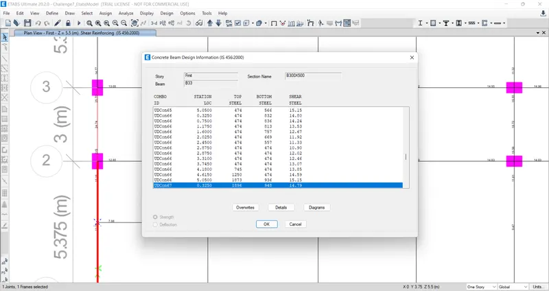
2.The beam along the mid span why it fails at span.
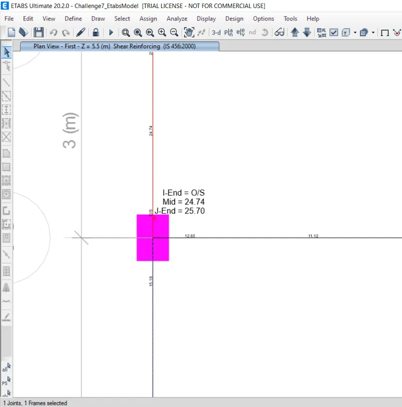
HERE WE CAN SEE O/S means over cross section.
right click on that beam .
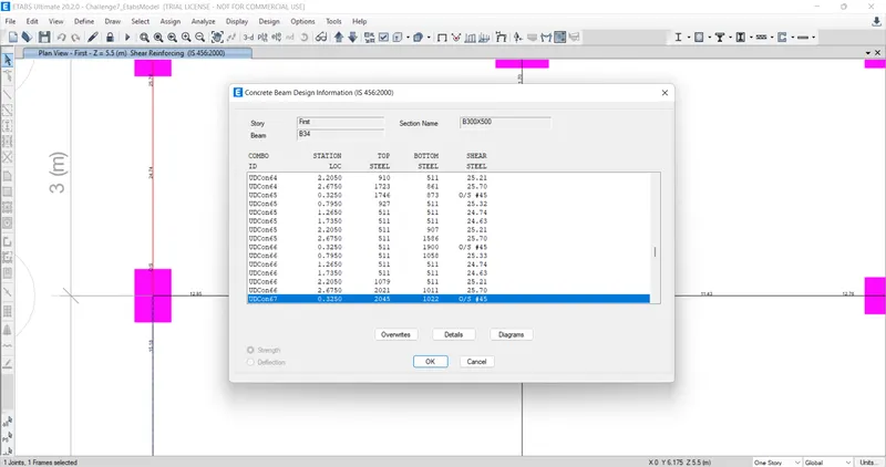
go to details.
and see the shear details.
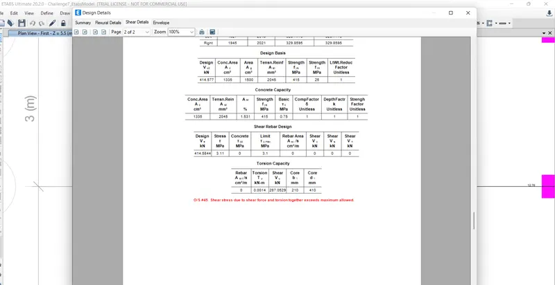
O/S -45 shear stress due to shear force and torsion togethar exceedss maximum allowed.
shaer stress is 415.577 kn is maximum.
where as torsion is 0.0014kn-m in nominal.
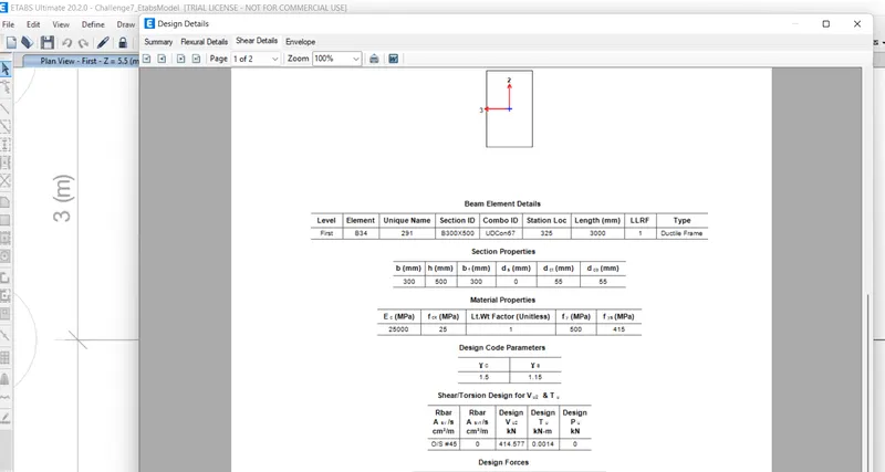
Shear reinforcement of beam at grid -3
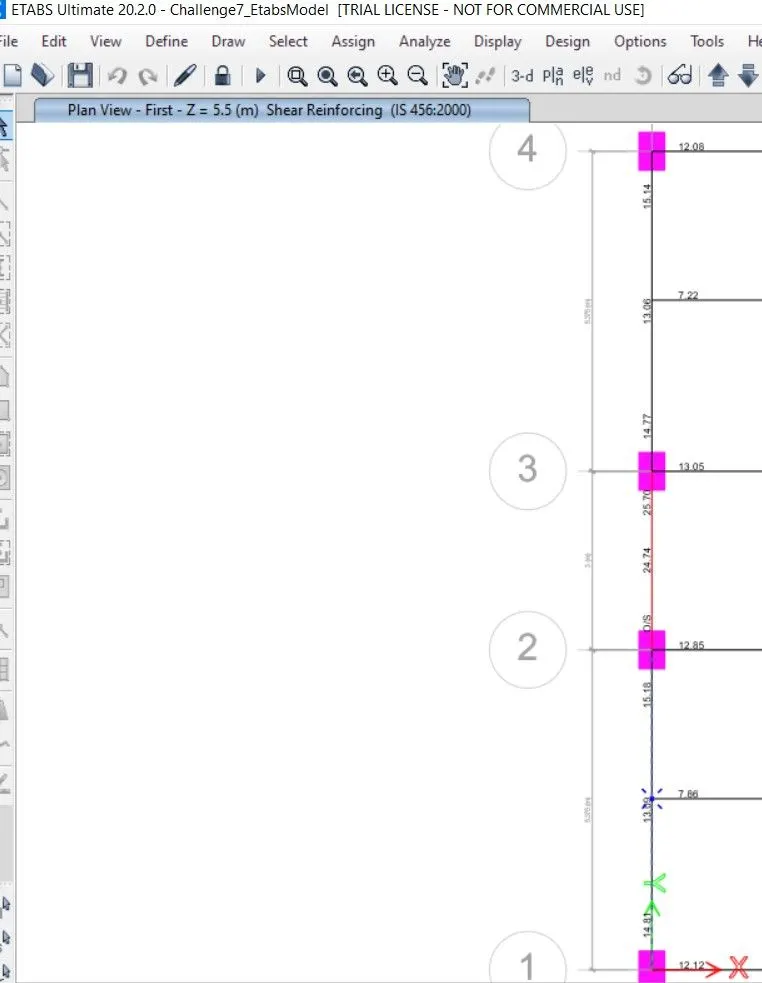
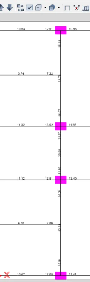
TOP REINFORCEMENT DETAILS AT GRID 3.

BOTTOM REINFORCEMENTDETAILS AT GRID 3.

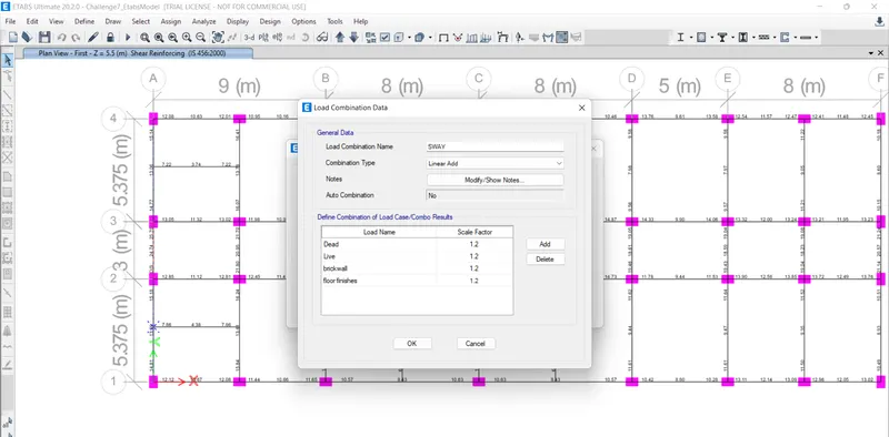
click on define option.
click on load combination.
add new combination.
add dead ,live brickwall, floor finish as 1.2 .
and then clock ok
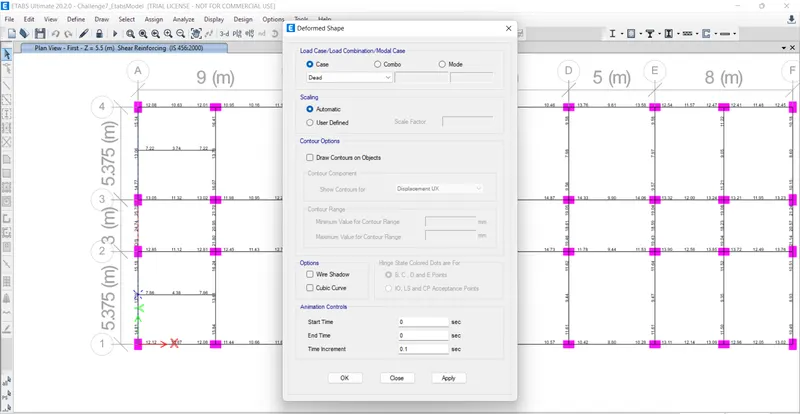
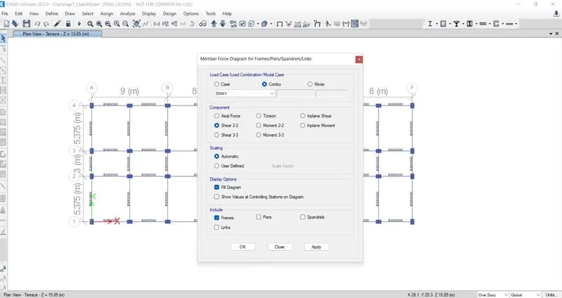
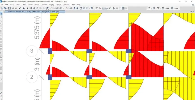
check the results for deformed shapes.
click on deformed shapes .
NOW COMING TO FINAL RESULT:
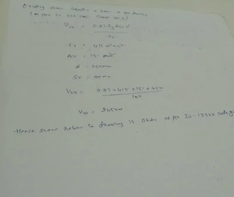
HENCE SHEAR REBAR CAN BE TAKEN AS 245KN IS OKAY. AS PER IS13920.