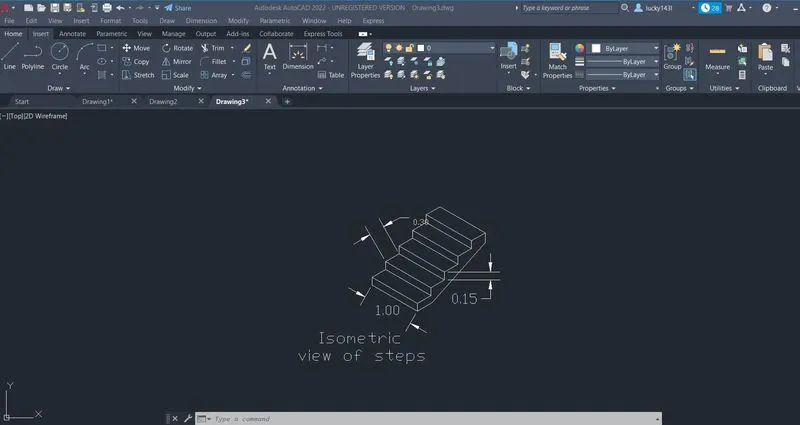
Creating a Floor plan, Footing detail and Isometric view using AutoCad
AIM: To Create a Floor plam,Footing details,and Isometric view using Auto cadd
procedure:
- Open Auto cadd software
- In the command bar type rectangle and press enter.
- specify first corner of rectangle.
- enter dimensions of length as 0.90 and width as 0.25.
- specify the other corner.
- specify line from Ribbon.
- specify next start point.
- specify next point @0.20,0
- specify next point @0,0.40
- specify next point @0.5,0
- specify next point @0,0.40
- specify next point @0.50,0
- specify next point @0,0.60
- specify next point @0.30,0
- specify next point @0,-0.60
- specify next point @0.50,0
- specify next point @0,-0.40
- specify next point @0.50,0
- specify next point @0,-0.40
- Press Esc line and then reselect line tool bar from command menu.
- specify next point @0,0.50
- specify next point @0.30,0
- specify next point @0,-0.05
- Press Esc line and then reselect line tool bar from command menu.
- specify next point @0,1
- specify next point @0.30,0
- specify next point @0,-1
- Press Esc line and then reselect line tool bar from command menu.
- specify next point @-0.30,0
- specify next point @-0.50,0
- specify next point @-1.15,0
- specify next point @0,-0.15
- specify next point @1.15,0
- Press Esc line and then reselect line tool bar from command menu
- specify next point @0.30,0
- specify next point @0,0.15
- specify next point @0.30,0
- specify next point @0,0.15
- specify next point @0.30,0
- specify next point @0,0.15
- specify next point @0.30,0
- Press Esc line and then reselect line tool bar from command menu.
- specify next point @1,0
- specify next point @0,-06.0
- specify next point @-0.95,0.
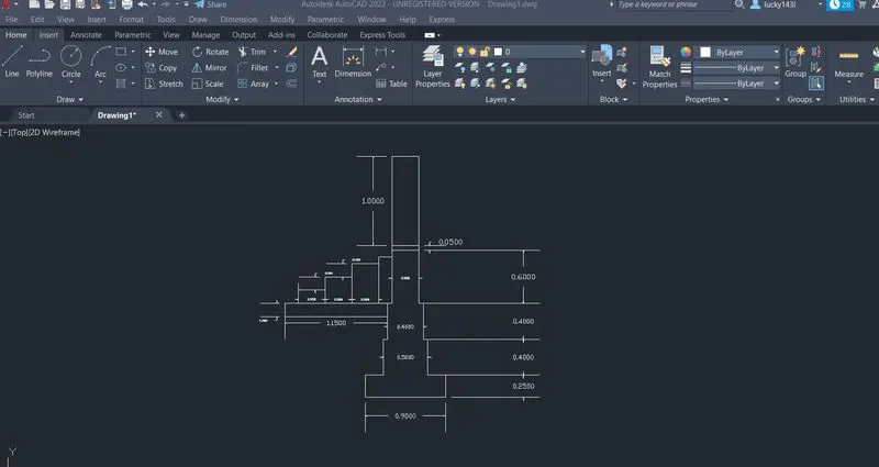
Isolated drawing:
- open auto cad and type QNEW.
- click on imperial
- set precession as 0.00 angle to decimal degree.
- Type Ds in command box.
- Snap spacing X & Y =0.5
- grid spacing X & y =0.5
- draw line command with line and give 1unit length.
- specify relative co-ordinate @0,0.015
- specify relative co-ordinate @0.38,0.25
- specify relative co-ordinate @0,0.016
- specify relative co-ordinate @0.24,0
- specify relative co-ordinate @0,-0.016
- specify relative co-ordinate @0.38,-0.25
- specify relative co-ordinate @0,-0.015
- Draw a line at a distance of 0.04 units from top with line command.
- Give the value 0.04 then give first line length as 1.96
- specify second line co-ordinates @-0.38,0
- specify third line co-ordinate @0,0.06
- copy first line by command copy and give value of 0.16
- copy the second line horizontal line by copy command and specify base point and drag to desired position.
- copy the third horizontal line and select the base point and drag it.
- give offset from top linewith an offset distance of 0.2 units.
- give command offset and select the object giving offset distance as 0.2 and select multiple options 9 for such line.
- Trim the excess line.
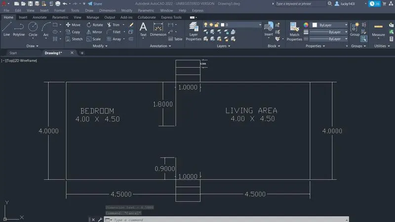
Dawing of two bedroom:
- open auto cad and type QNEW.
- click on imperial
- set precession as 0.00 angle to decimal degree.
- Type Ds in command box.
- Snap spacing X & Y =0.5
- grid spacing X & y =0.5
- select polyline from ribbon and create a room dimension 4.0x 4.5
- command poly and click a pointthen move the cursor towards south and give 0.9 units.
- move the cursor to west and give 4.0 units.
- move to north and gives distance of 4.5 units and then move to east and give 4.0 units
- and finallyto south 1.8 units.
- the stap ouline is created by using line command.
- now from the corner point of 1.8 unitsdraw a vertical line at a distance of 0.9 nits.
- move the cursor to east and give a distance of 1 units.
- move to south with 0.9 units.
- now draw living room is drawing using polyline also.
- give command polyfrom the last point and then start the poly line.
- give 4.2 units in the east.
- now move to south and go 4.0 units
- move to west and go 4.5 units.
- create outline step again.
- specify command line andselect last line drawn.
- move to south and go 0.9 units
- move to west and go 1.0 units.
- move to north and go 0.9 units.
- create the steps with offset command and give 0.3 units sistance by selecting object.
- click on the multiple and move the cursor to the direction where it is drawn.
- Reapeat on another side.
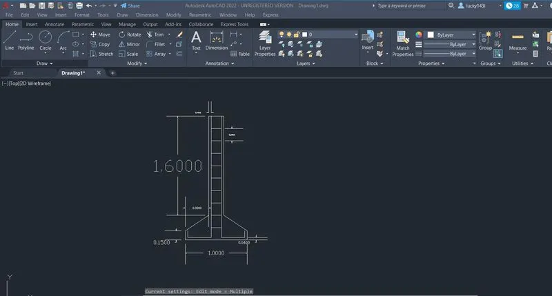
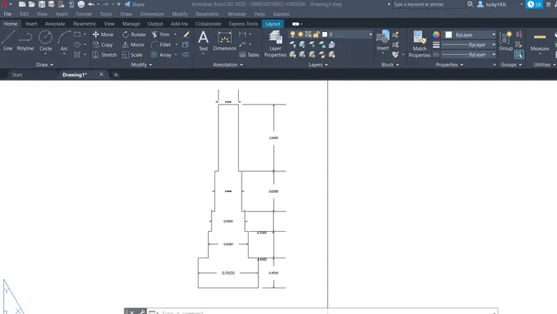
Cross section of load bearing walls:
- open auto cad and type QNEW.
- click on imperial
- set precession as 0.00 angle to decimal degree.
- Type Ds in command box.
- Snap spacing X & Y =0.5
- grid spacing X & y =0.5
- create a rectangle by choosing rectangle
- specify dimension length =0.9 and width 0.45
- select poly line from ribbonand specify first point 0.15 unitsfrom the corner of the rectangle
- with the cursor pointing north go 0.4 units
- move east by 0.05 units
- move north by 0.3 units
- move east by 0.5 units
- move north by 0.6units
- move east by 0.4units
- move southby 0.6 units
- move east by 0.05 units
- move south by 0.4 units
- the top portion is drawn by polyline select poly from ribbon and give distance of 0.05 units.
- move north by 1 units
- move east by 0.3 units
- move north by 1 units
STEPS in ISOMETRIC VIEW:
- open auto cad and type QNEW.
- click on imperial
- set precession as 0.00 angle to decimal degree.
- Type Ds in command box.
- Active the isometric view from toogle barthen snap off grid ,make sure grid is on
- from isometric drafting select isoplane left
- select line tool from ribbon and move towards west by 1 units
- move towards north by 0.15 units
- move towards east by 1 unit and south by 0.15 units.
- change the isometric draft by isoplane top
- move the cursor backand give 0.3units frm the last drawn point.
- move to front and go by 0.3 units.
- change the isometric drafting by isoplane right.
- copy the object with orthooff
- command co and specify the base pointand place it in a new poitn for 4 steps.
- with isoplane right draw a horizontal distance of 0.3 unitsfrom starting point of the chair.
- draw a vertical distance of 0.15 units from the last stair.
- join the two points with the ortho off and the stair is drawn.