Advanced Sheet Metal Design Using NX Cad Challenge_6_Bracket
Advanced Sheet Metal Design Using NX Cad Challenge – Metal Bracket I
Objective –
- To design sheet metal bracket using Siemens NX Cad.
- To learn the various features and commands use in the creation of metal bracket.
Introduction - In NX, sheet-metal parts can be folded and unfolded enabling you to show them in the flat pattern as well as their bent-up state. There are two ways to design sheet-metal parts in NX. Either you can start the sheet-metal part from scratch using sheet-metal features throughout the design process or you can design it as a regular solid part and later convert it to a sheet-metal part. Most commonly, you design sheet-metal parts in Sheet Metal environment from the begining.
Design Methodology –
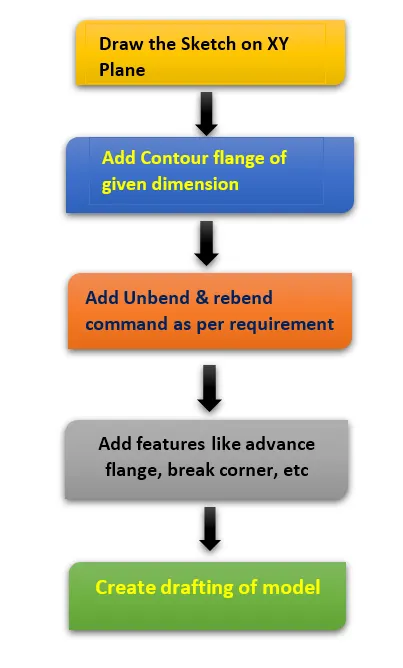
Description of command used –
Contour Flange - The contour flange is another basic type of sheet metal feature. In order to create a contour flange, you need to have an open sketch. Activate the Contour Flange command (click Home > Bend > Contour Flange on the ribbon) and click on elements of an open sketch. Drag the arrow or type-in a value in the Width box to define the width of the contour flange.
Normal Cut-out - When it is necessary to remove material from a sheet metal part, you must use the NormalCutout command. First, draw a sketch, and then activate the Normal Cut-out command. Click on the sketch and select the extent type from Cut-out Properties > Limits. Type-in a value in the Depth box in case the Limits is set to Value. On the dialog, click OK to create the cut-out.
Beads- The Bead command creates a bead feature, which stiffens the sheet metal part. In order to create a bead feature, first you must have a sketch, which defines the bead size and shape. If the sketch is having curved edges, then ensure that they are tangent continuous. Activate the Bead command (click Home > Punch > Bead on the ribbon) and click on the sketch. On the Bead dialog, click the Reverse Direction button to flip the bead feature.
Hole – It is the feature used to create throughout circular cut out of required diameter on body.
Break Corner- The Break Corner command rounds or chamfers the sharp corners of a sheet metal part.
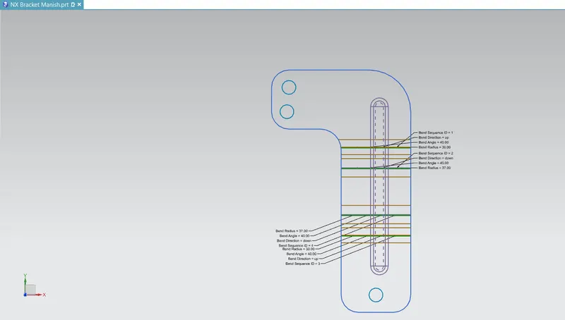
Flat Pattern- This feature is used to create an instance of the flat shape and size of the sheet metal that required to create final part.
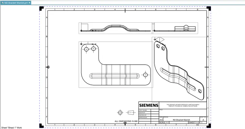
Drafting - After creating 3D model of sheet metal box assembly it can be converted in 2D drawing on sheet for the easy interpretation of model.
Different Views of Model -
Top View
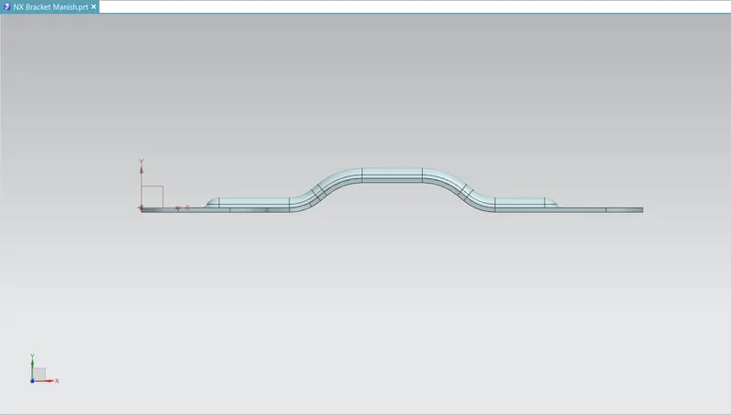
Front View
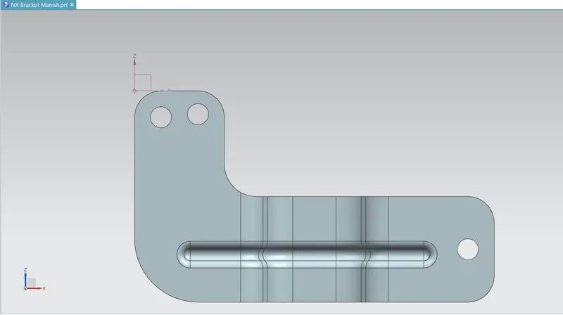
Left View
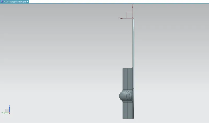
Right View
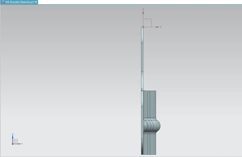
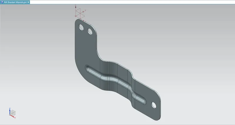
Isometric View
Flat pattern
Drafting
Conclusion –
- Design sheet metal bracket successfully by using NX cad.
- Learn features used in the creation of model.