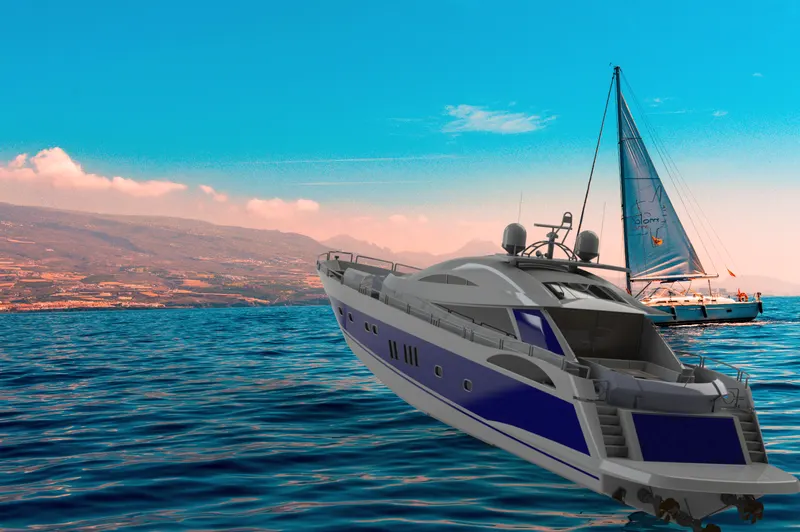
Radar Mast & Final Assembly of Yacht
REPORT ON SUN SEEKER PREDATOR YACHT
OBJECTIVE:
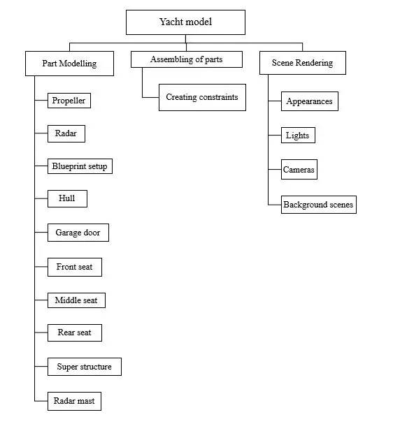
- To design individual parts of the yacht with fully defined sketches and appropriate appearances.
- To assemble all the individual parts of the yacht model .
- To render the yacht model by adding appearances ,decals ,light ,cameras ,and background scenes.
INTRODUCTION
Solidworks is one of the prominent modelling software available .This software is mainly used to model 3d parts using 2D sketch .It also has the option to specify the material and look for the model which we create .It has the option to specify the material and look for the module which we create .It has add-in-features like 360 which helps in rendering of the final model to make it look photo realistic. In this project we will learn about design of an American chopper parts and assembling them and rendering the final chopper after the assembly.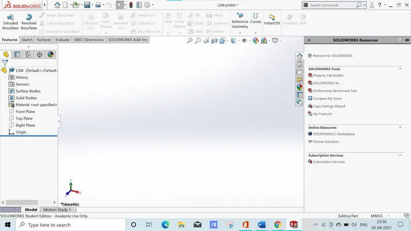
YACHT
yacht is a sail or power vessel used for pleasure, cruising, or racing. There is no standard definition, so the term applies to such vessels that have a cabin with amenities that accommodate overnight use. To be termed a yacht, as opposed to a boat, such a pleasure vessel is likely to be at least 33 feet (10 m) in length and may have been judged to have good aesthetic qualities.
The Commercial Yacht Code classifies yachts 79 ft (24 m) and over as large. Such yachts typically require a hired crew and have higher construction standards. Further classifications for large yachts are: commercial—carrying no more than 12 passengers, private—solely for the pleasure of the owner and guests, or by flag, the country under which it is registered.
Racing yachts are designed to emphasize performance over comfort. Charter yachts are run as a business for profit. As of 2020 there were more than 15,000 yachts of sufficient size to require a professional crew.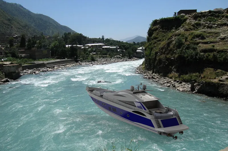
DESIGN METHODOLOGY:
- Sketch
Sketch is a two dimensional representation for converting 2D sketch to 3D modelling. In solidworks , there are different sketch options to create a sketch and these are known as sketch entities – lines, circle, arc , rectangle etc
- Extrude boss
This feature is to convert 2D into solid modeling only when the 2D into a solid modeling only when 2D sketch is completely closed. It also allows to extrude the surface in both directions and also offset is to require distance.
- Fillets
This is to create a curve surface on the profile edges on solid model by selecting the required lines or the faces the fillet also has a feature to select multiple lines which reduce time consumption.
- Extrude cut
It is used to remove materials from a solid model in desired patterns and also it can be extruded with both directions.
- Split tool
This tool is very handy ,when two or more solid body intersect in between or intersect each other then split tool allows to delect unwanted solid body formation gives a clean look.
- Trim entities
There are two types of entities:
- Extend entities- which allows the broken lines to intersect each other and this can be done only in 2D sketch.
- Trim entities- this helps to remove unwanted lines which are intersecting.
- Swept surface
surface generated from section curve positioned along the path.
- Chamfer
It is similar to the fillet feature but in chamfer ,it cuts the solid model intersection area into recurred length and angle.
- Dynamic mirror
To make the solid body identical to each other this feature is used.
- Combine
Combine feature is used to combine two or more bodies when intersecting to each other and make it single body.

Fig- feature tab

Fig- sketch tab

Fig- surface tab

Fig- rendertool tab
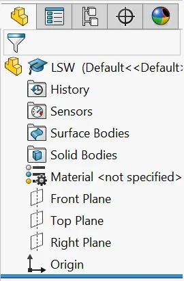
Fig-feature tree
Modelling of individual parts
- Propeller
- Radar
- Hull
- Blueprint setup
- Garage door
- Front seat
- Middle seat
- Rear seat
- Super structure
- Radar mast
Propeller
A propeller is a device with a rotating hub and radiating blades that are set at a pitch to form a helical spiral, that, when rotated, performs an action which is similar to archimedes screw. It transforms rotational power into linear thrust by acting upon a working fluid, such as water or air. Therotational motion of the blades is converted into thrust by creating a pressure difference between the two surfaces. A given mass of working fluid is accelerated in one direction and the craft moves in the opposite direction. Propeller dynamics, like those of aircraft wings, can be modelled by bernoullis principle and newtons third law. Most marine propellers are screw propellers with helical blades rotating on a propeller shaft with an approximately horizontal axis.
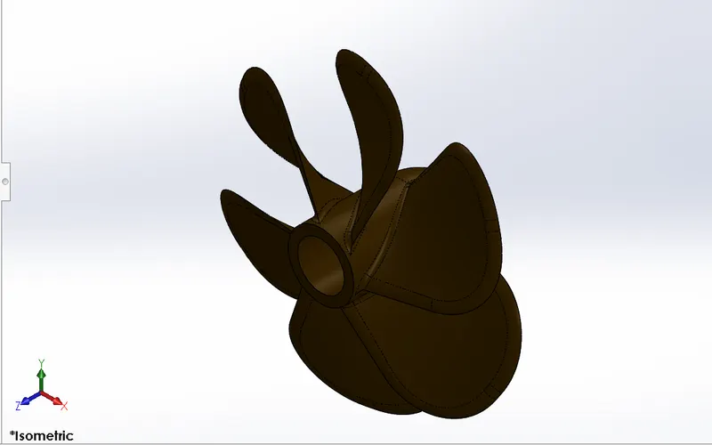
FEATURES USED TO CREATE PROPELLER
- Sketch
- Line
- Circle
- Loft
- Rectangle
- Revolve
- Circular pattern
- Extrude cut
RADAR
Radars provide the benefit of line-of-sight target detection in low or no visibility situaitons. First you must choose the radar platform. Radome is more compact and open-array is bigger.
You can then narrow your selection by choosing either pulse radar, which is better at long range, or broadband radar which has instant-on capability and better short range resolution. Lastly select the radar power output, the larger the wattage the better the range and the target seperation.
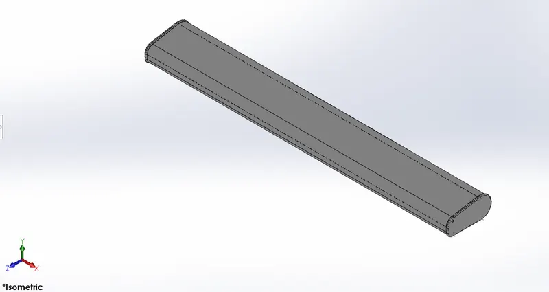
Features used to create radar
- Sketch
- Extrude
- Fillet
- Line
- Polygon
- Circle
- Text
- Mirror
HULL
Radars provide the benefit of line-of-sight target detection in low or no visibility situaitons. First you must choose the radar platform. Radome is more compact and open-array is bigger.
You can then narrow your selection by choosing either pulse radar, which is better at long range, or broadband radar which has instant-on capability and better short range resolution. Lastly select the radar power output, the larger the wattage the
better the range and the target seperation.
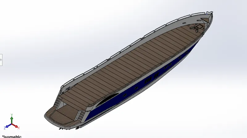
Features used to create hull
- Sketch
- Offset
- Entities
- Project curves
- Lofted surface
- Trim surfaces
- Exteuded surfaces
- Knit surface
- Filled surface
- Shell
- Extruded boss
- Fillet
- Chamfer
- Swept boss
- Revolved boss
- Dome
- Helix
- Linear pattern
- 3d sketch
- Mirror
- Split body
- Offset surface
FRONT SEAT
A seat is a place to sit. The term may encompass additional features, such as back, armrest, head restraint but also headquarters in a wider scene. It is designed with refrence to the deck surface and the blueprints. It is designed using surface are applied to the surfaces features and also extrude features. Domes are applied to the surfaces to imitate the cushions of the seat. The front seat is designed on the front to have the perfect view of the ocean and accommodate 2 people.
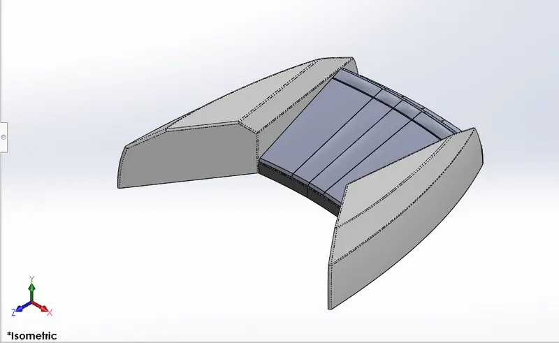
Features used to create frontseat
- Plane
- Sweep
- Surface loft
- Surface trim
- Extrude cut
- Revolve
- Surface knit
- Surface fill
- Dome
- Mirror
- Fillet
- Chamfer
Middle seat
The middle seat is designed to accommodate more people. It can accommodate 6 people and a table is provided at the centre. This is located between superstructure and the rear seat. This seat is u shaped seat .it lies behind the super structure of the yacht.
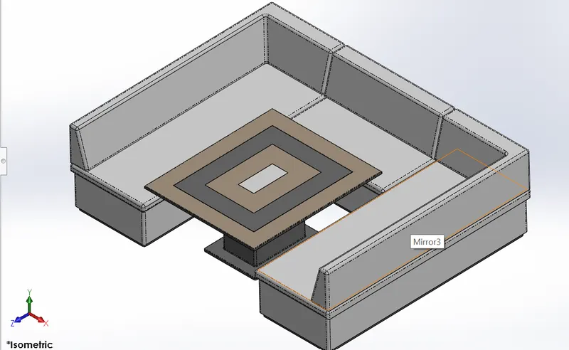
Features used to create middle seat
- sketch
- Extrudeboss
- Chamfer
- Mirror
- Line
- Rectangle
- Offset entities
- Extrude cut
Rear seat
A seat isaplace to sit. The term may encompass additional features such as back,armrest,headrestraint but also headquarters in a wider sense.it may also come under luxuries,material use for seat etc.
Surface feature are employed more in seat than in others.
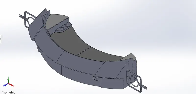
Features used to create rear seat
- Sketch
- Surface extrude
- Surface loft
- Surface offset
- Surface trim
- Sweep
- Ruled surface
- Surface extend
- Extrude boss
- Chamfer
- Extrude cut
- Mirror
- Plane
- Fillet
,
Superstructure
On water craft, the superstructure consists of the parts of the ship or a boat, includingsailboats, fishingboats, passenger ships, and submarines, that project above her main deck. This does not usually include its masts or anyarmament turrets. Note that in modern times, turrets do not always carrynaval, but they can also carrymissile launcher and/oantisubmarine warfare weapons.
The size of a watercraft's superstructure can have many implications in the performance of ships and boats, since these structures can alter their structural rigidity, their displacements, and/or stability. These can be detrimental to any vessel's performance if they are taken into consideration incorrectly.
The height and the weight of superstructure on board a ship or a boat also affects the amount of freeboard that such a vessel requires along its sides, down to her waterline. In broad terms, the more and heavier superstructure that a ship possesses (as a fraction of her length), the less the freeboard that is needed.
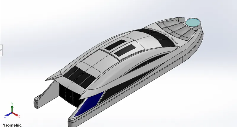
Features used to create the superstructure
- Line
- Spline
- Circle
- Extrude cut
- Projected curves
- Offset
- Surface fill
- Surface extrude
- Surface sweep
- Dome
- Surface trim
- Extend surface
- Surface knit
- Plane
- Ruled surfaces
- Split entities
- Deleted faces
- Fillet
- Chamfer
- Mirror
Radar mast
Marine radars are x band or s band radar on ships, used to detect other ships and land obstacles, to providebearingand distance forcollosion avodiance and navigation at sea. They are electronic navigation instruments that use a rotatingantenna to sweep a narrow beam of microwaves around the water surface surrounding the ship to the horizon, detecting targets by microwaves reflected from them, generating a picture of the ship's surroundings on a display screen.
Radar is a vital navigation component for safety at sea and near the shore. Captains need to be able to maneuver their ships within feet in the worst of conditions and to be able to navigate "blind", when there is no visibility at night or due to bad weather. In addition to vessel-based marine radars, in port or in harbour, shore-basedvessel traffic service radar systems are used by harbomasters and coast guard to monitor and regulate ship movements in busy waters.
Radars are rarely used alone in a marine setting. A modern trend is the integration of radar with other navigation displays on a single screen, as it becomes quite distracting to look at several different screens. Therefore, displays can often overlay an electronic gps of ship position, and asonar display, on the radar display. This provides a combined view of surroundings, to maneuver the ship.
In commercial ships, radars are integrated into a full suite of marine instruments including sonar, two-waymarine radio satellite navigation receivers such as the US GPS, ande ergency locator. With digita to exchange data, these devices advanced greatly in the early 21st century. For example, some have 3D displays that allow navigators to see above, below and all around the ship, including overlays ofsatellite amazing.
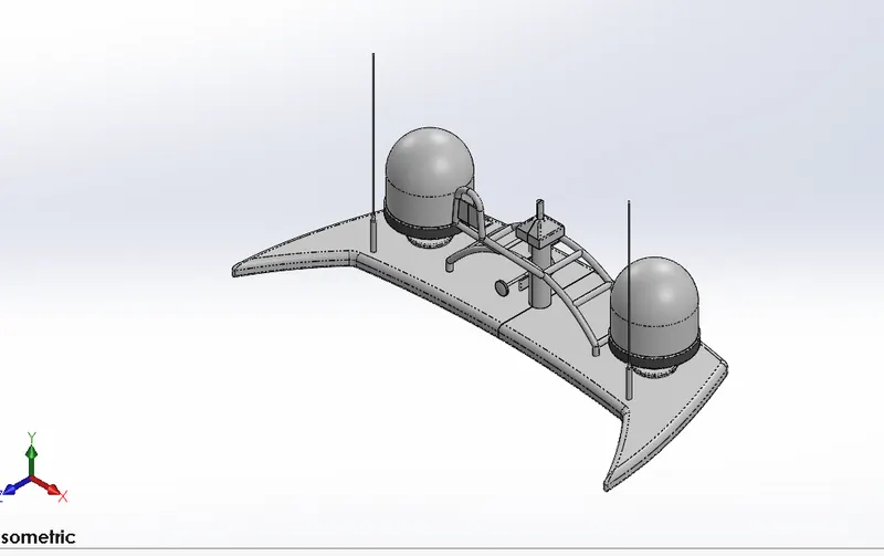
Features used to create radar mast
- Sketch
- Spline
- Extrude boss
- Revolve
- Circle
- Mirror
- Line
- Fillet
- Chamfer
- Shell
- Projected curve
Garage door
It’s a door for the garage. A garage door is a large door on a garage that opens either manually or by an electic motor. Garage doors are frequently large enough to accommodate automobiles and other vehicles. Small garage doors may be made in a single panel that tilts up and back across the garage doors may be made in a single panel that tilts up and back across the garage ceiling.
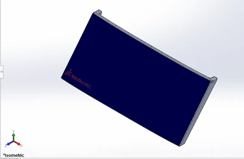
Features used to create garage doors
- Sketch
- Mirror
- plane
- Text
- Shell
Assembly
The assembly of yatch is quite simple since wehave taken the base deck surface for the most of the parts it gets mated automatically although some mates are used to assemble the yatch.
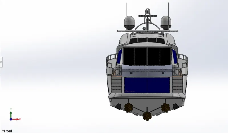
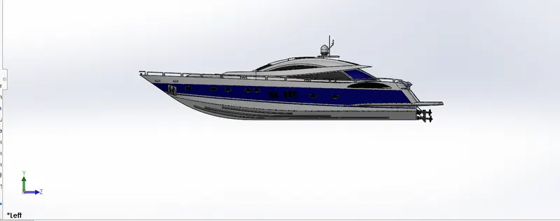
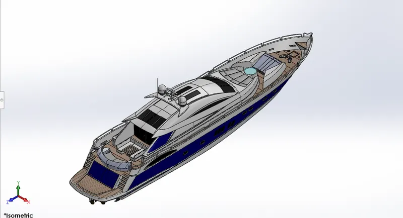
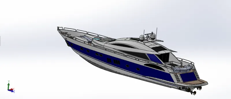
Mates used
- Coincident
- Concentric
- Angle limit
Rendering using photoview 360
PhotoView 360 is a SOLIDWORKS add-in that produces photo-realistic renderings of SOLIDWORKS models. The rendered image incorporates the appearances, lighting, scene, and decals included with the model. PhotoView 360 is available with SOLIDWORKS Professional or SOLIDWORKS Premium.
- With a model open, click Tools > Add-In and add in PhotoView 360.
- Start a preview in the graphics area or open thepreviewwindow to see how changes you make to the model affect the rendering.
- Edit appearance, the scene , and decals.
- Edit lights
By default, lighting is off in PhotoView. With lights off, you can use the realistic lighting provided by scenes, which is usually sufficient for rendering. You typically need additional lighting in PhotoView to illuminate occluded spaces in the model.
- Edit photoview options
- When you are ready, perform a final render either now (PhotoView > Final Render ) or later ( PhotoView > Schedule Render ).
If annotations or dimensions are visible in your model, a dialog box appears with options to include the dimensions and annotations or render without them.
If you have not added a camera or turned on perspective view, which provide more realistic, higher quality renderings, a dialog box appears. You can turn on a camera or perspective view from the dialog box or continue without them.
- Make detailed adjustments in thefinal render window
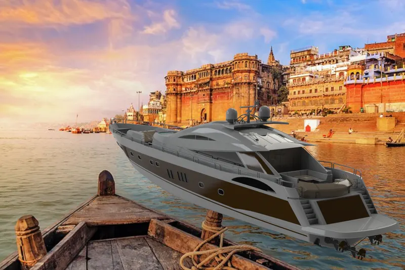
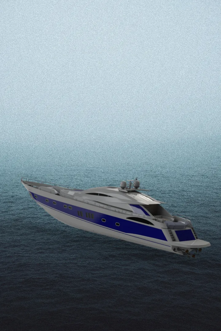
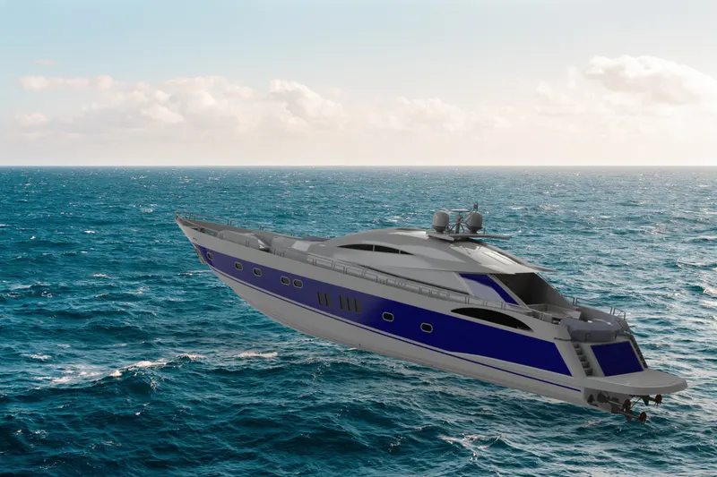
Conclusion
To conclude design , assembly and rendering of the sun seeker predator yachtare done using solidworks.