Advanced Sheet Metal Design Using NX Cad Challenge_6_Bracket
Title of project- advanced sheet metal design using nx cad.
Objective- to create and design a bracket using nx cad.
Introduction- Sheet metal is metal formed by an industrial process into thin, flat pieces. sheet metal is one of the fundamentals forms used in metal working and it can be cut and bent into a variety of shape. Countless everyday objects are fabricated from sheet metal thickness can vary significantly ; extremely thin sheets are considered foil or leaf and pieces thicker than 6mm are considered plate steel or “structural steel”.
NX, formerly known as "unigraphics", is an advanced high-end CAD/CAM/CAE, which has been owned since 2007 by Siemens PLM Software. In 2000, Unigraphics purchased SDRC I-DEAS and began an effort to integrate aspects of both software packages into a single product which became Unigraphics NX or NX.
Design methodology

- Create a sketch
- Add features like contour flange, normal cutout break corner to achieve desired shape
- Unbend the component.
- After unbending draw a line and add bead.
- Rebend the unbend component.
- Add hole of desired radius.
Features used in modelling
- Sketch- it is basic of any design.
- Contour flange- -a contour flange is defined using a profile sketch and a straight edge on an existing face.
- Normal cut out-it is used to remove the desired material from that profile.
- Break corner- used to break the two line coinciding each other.
- Unbend- it is a very important feature before creating any feature the model should unbended for easy understandings.
- Rebend - rebend of unbend profile is called rebending.
- Holes- it add a hole to one or more solid bodies in a part of assembly with options for counterboard, counter sunk and threaded.
Screenshot of model-
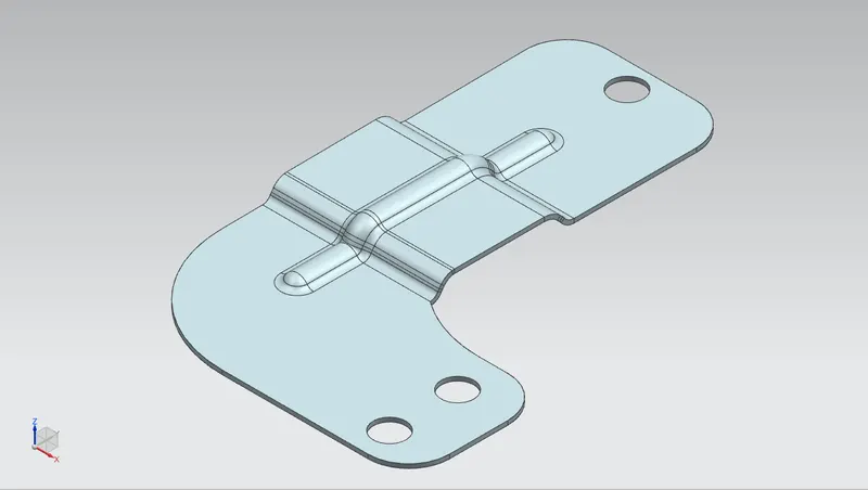
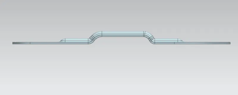
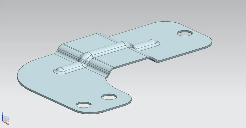
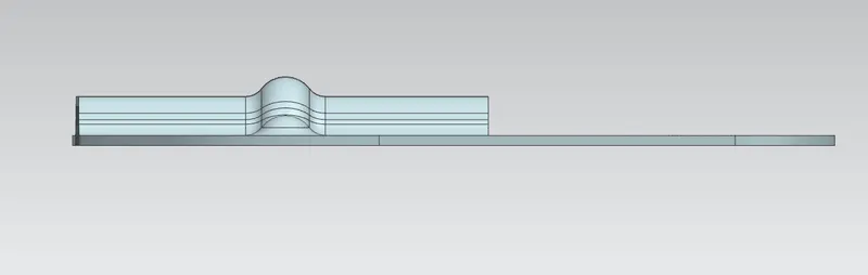
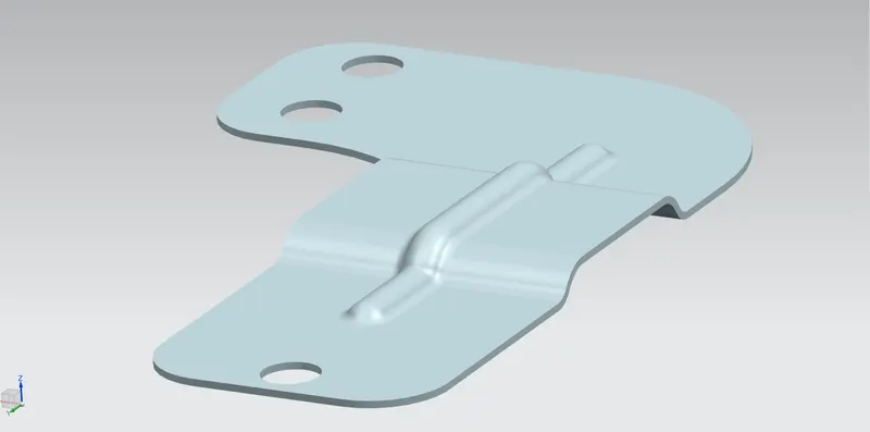
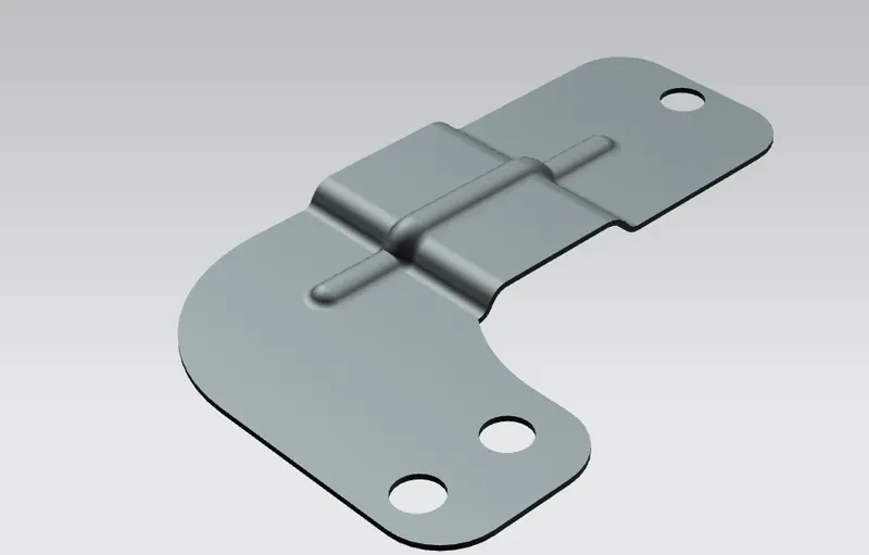
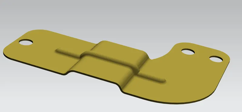
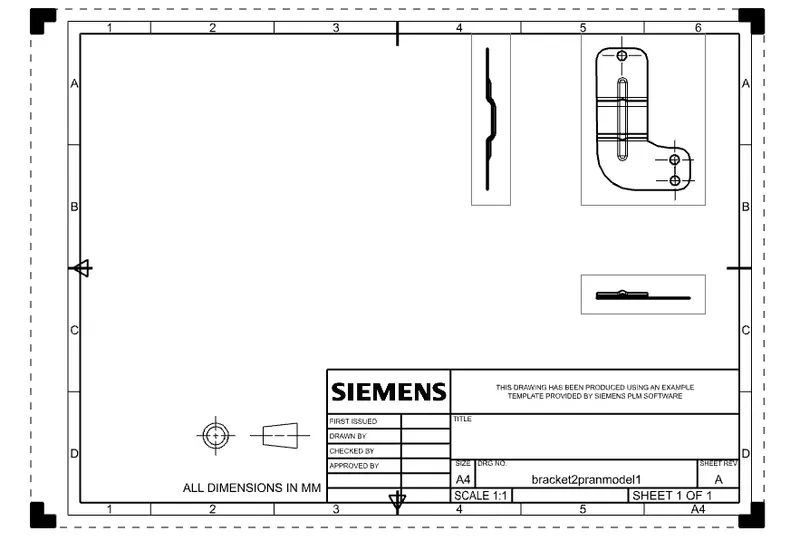
Conclusion
the sheet metal design was completed by using basic command like contour flange, bead ,normalcutout etc.