Radar Mast & Final Assembly of Yacht
Report on Yacht Modelling
Title of the Project
Yatch Modelling
Objective
to model all the parts independently and finally seemble them in the form of Yatch assembly
Introduction
a yatch has many separate parts, these are:
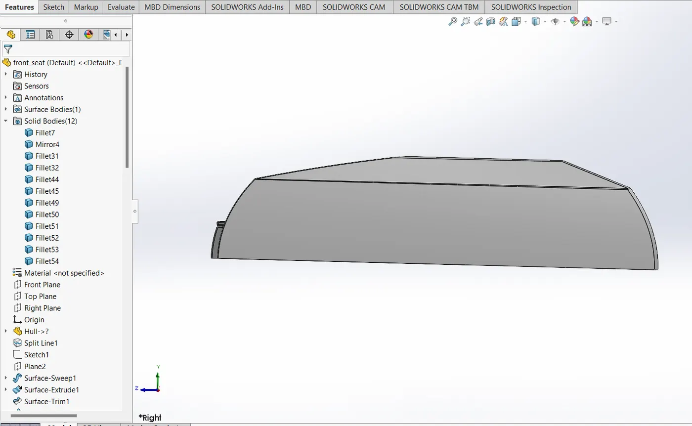
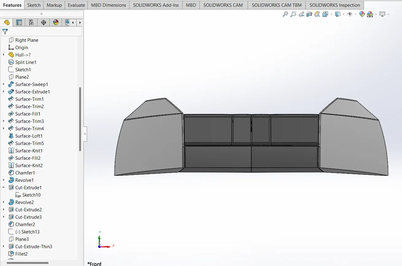
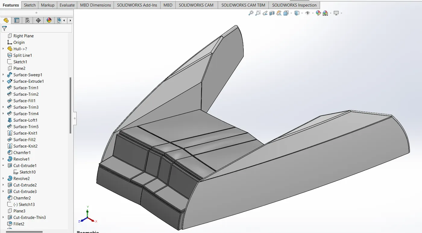
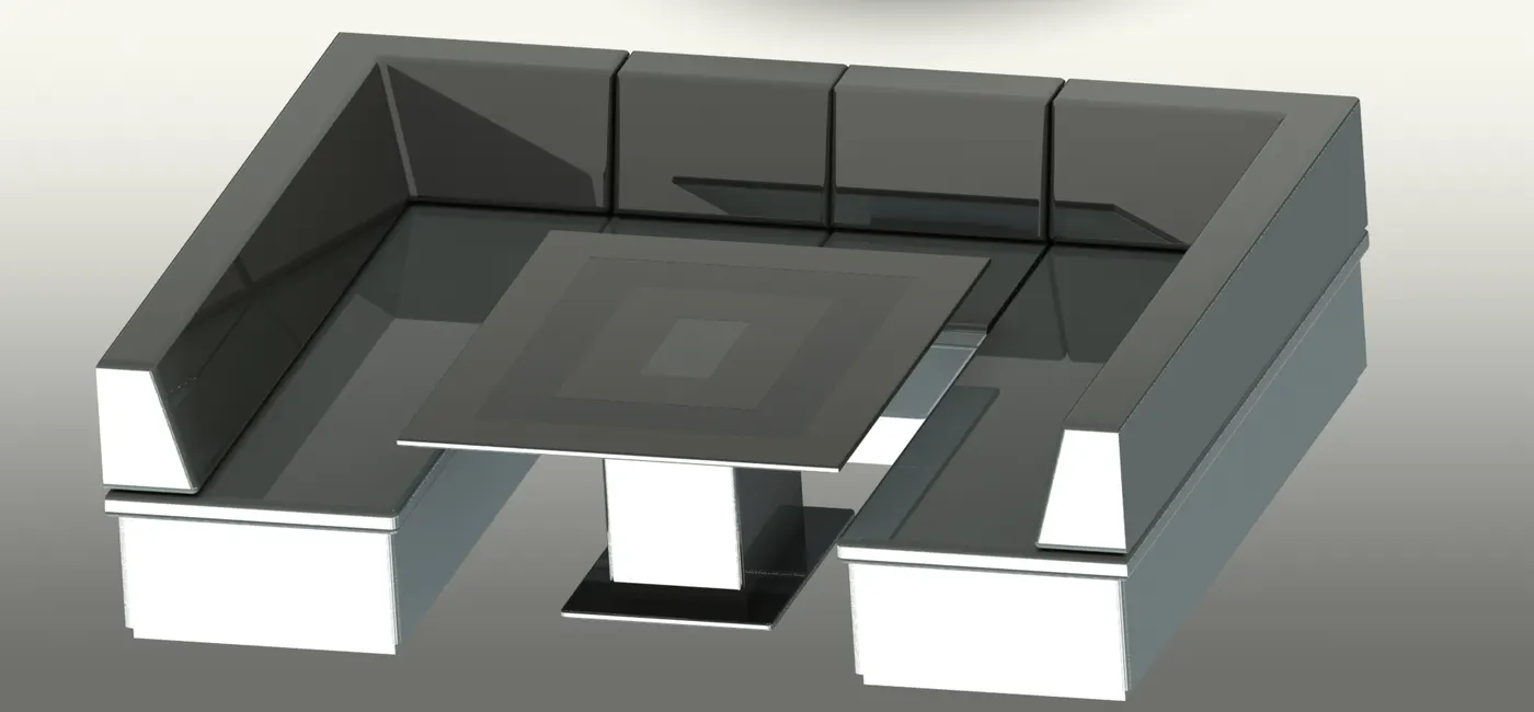
front seat
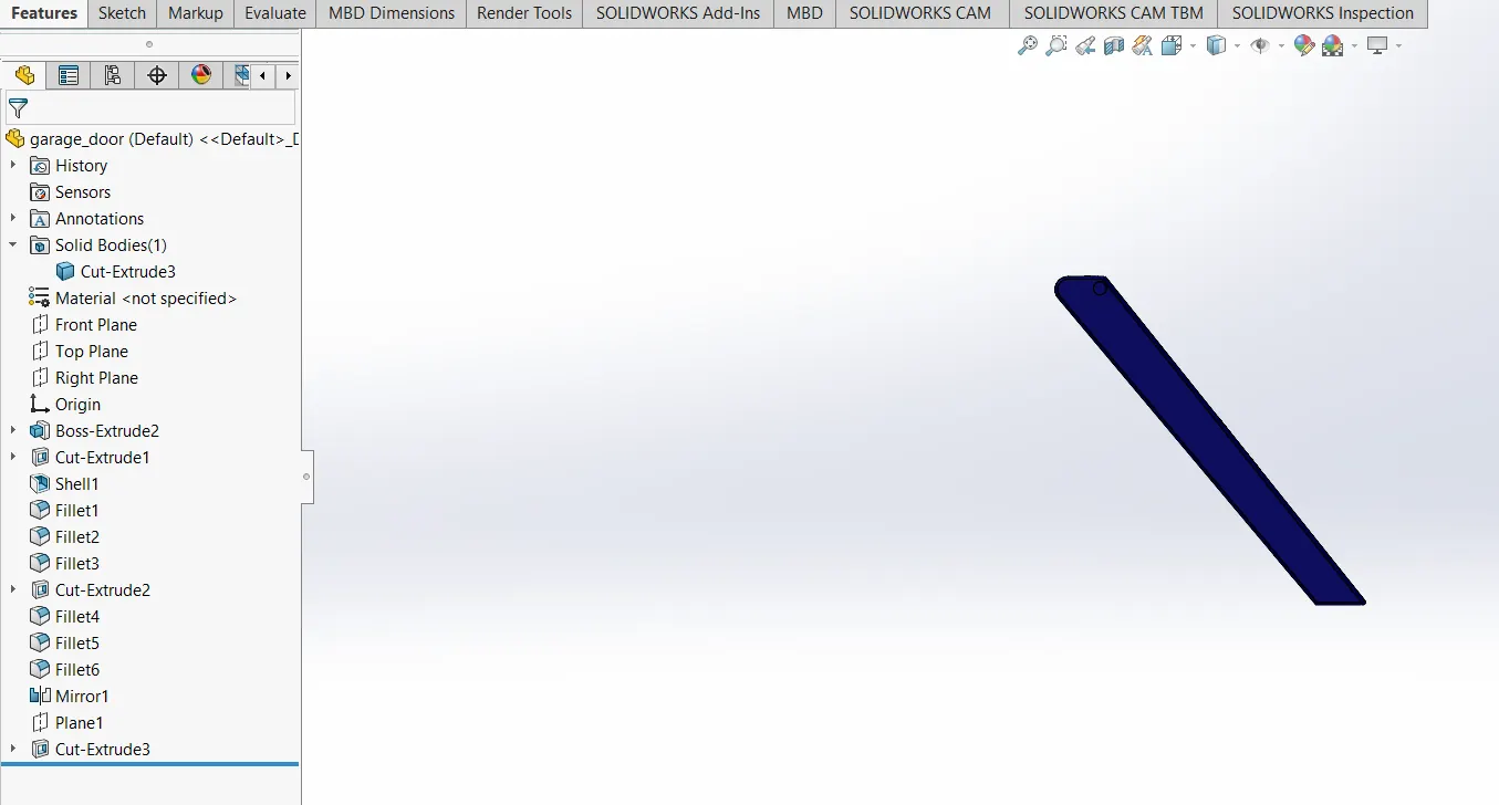
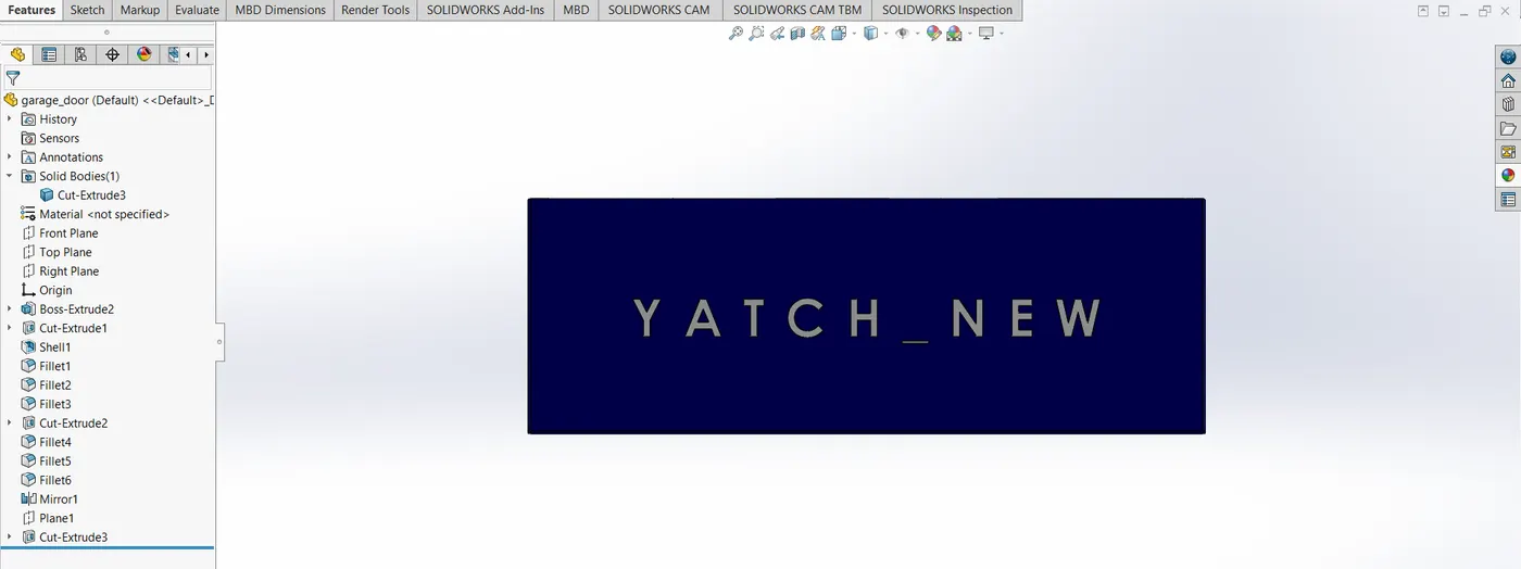
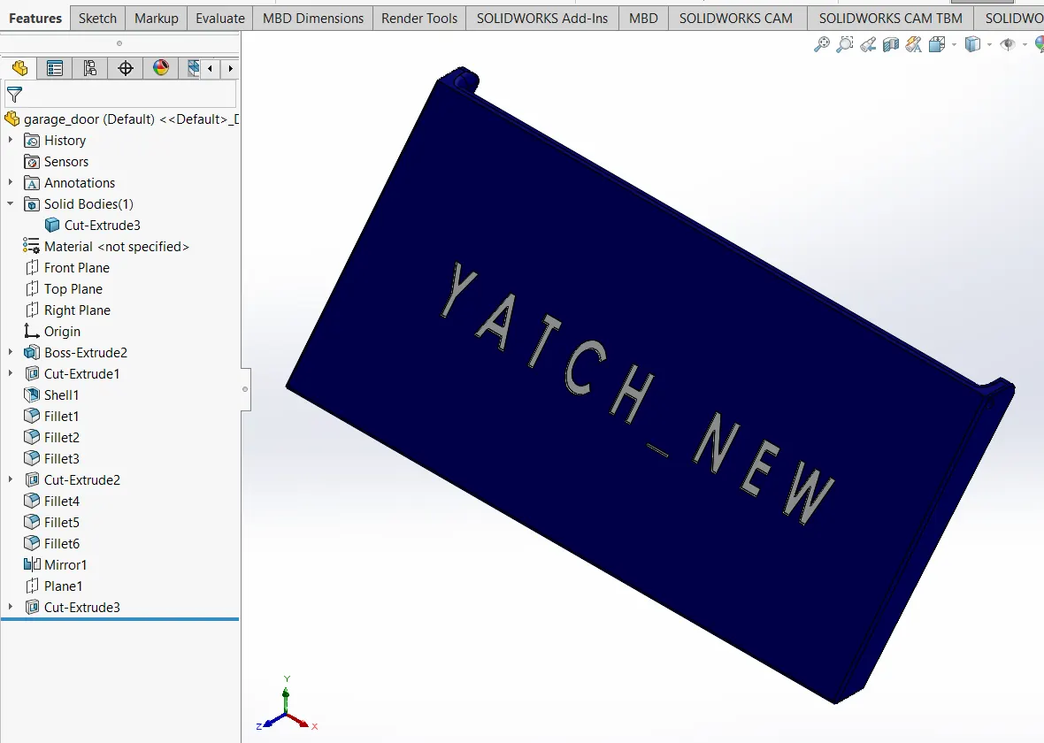
garage door
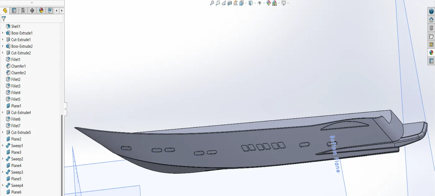
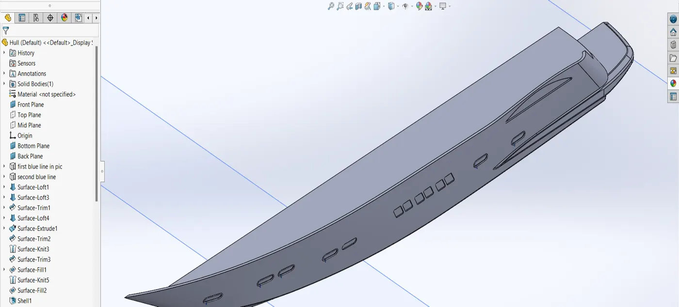
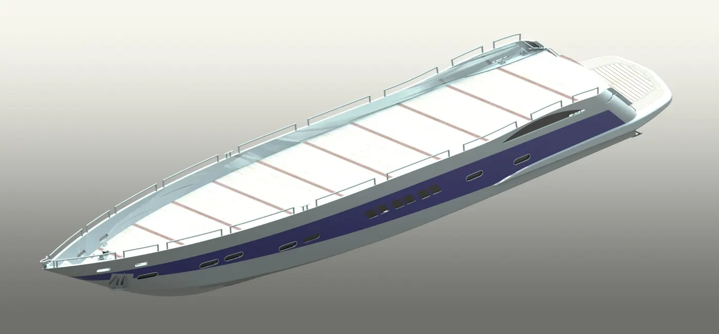
hull
middle seat
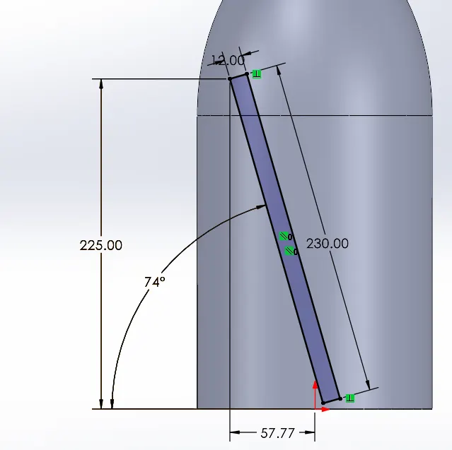
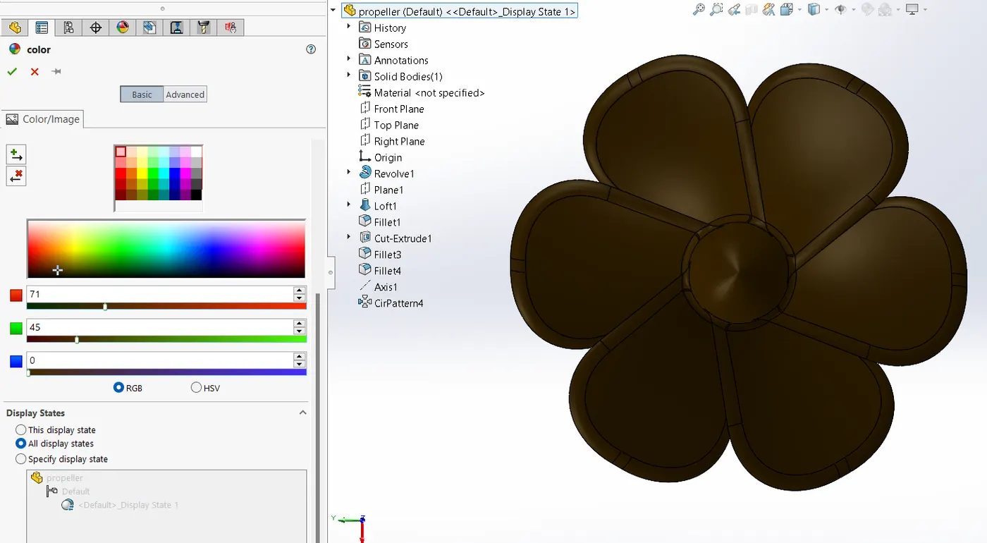
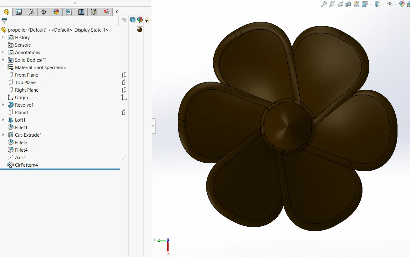
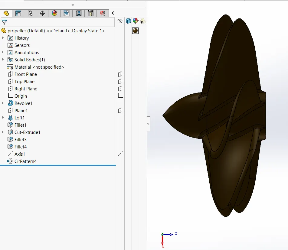
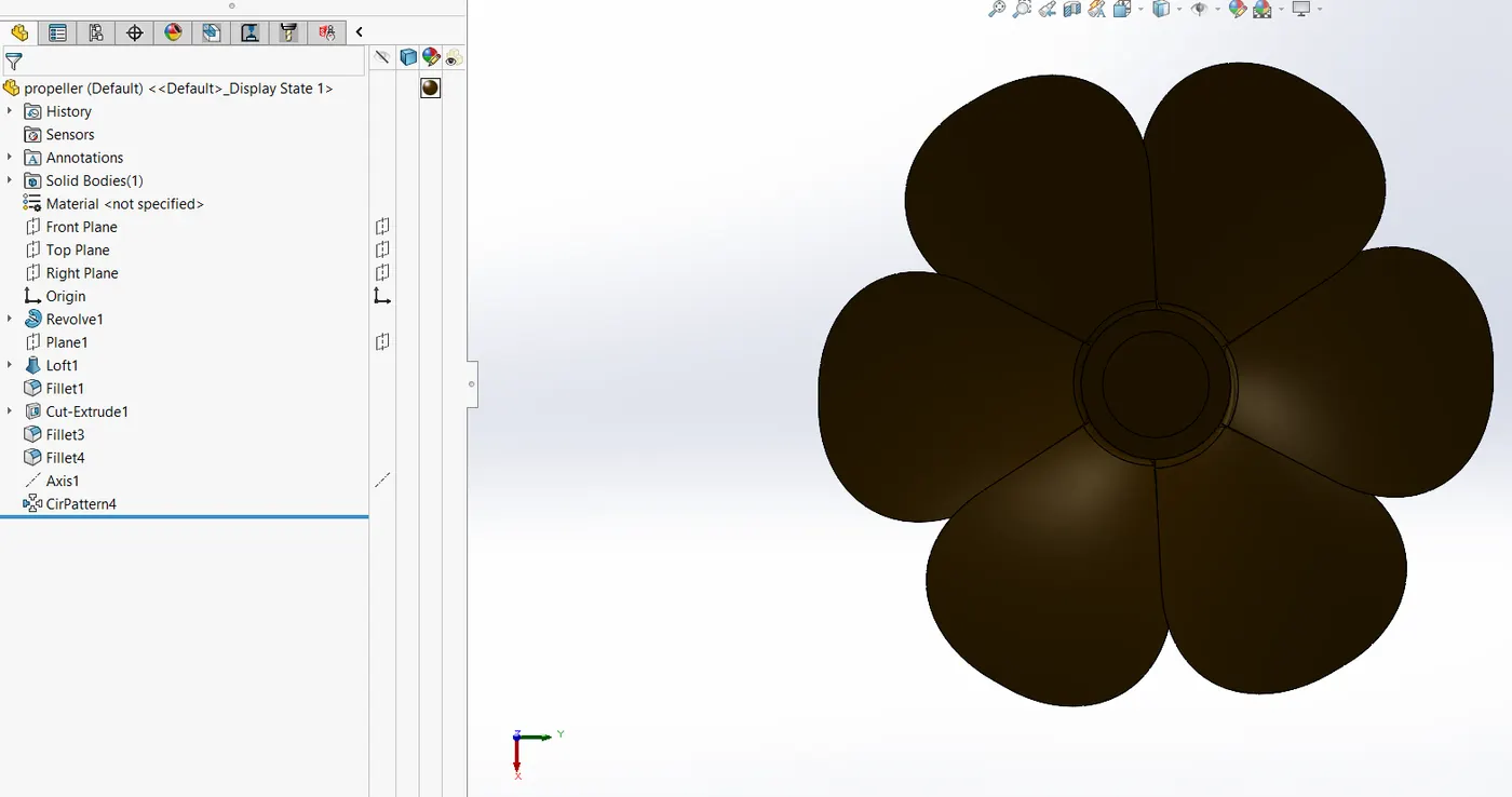
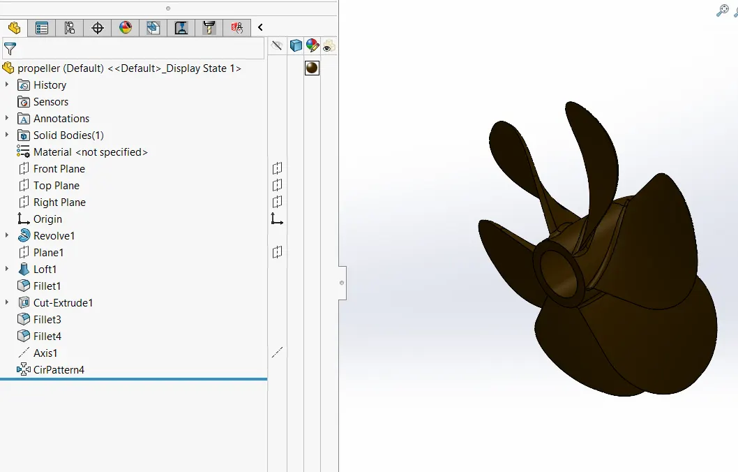
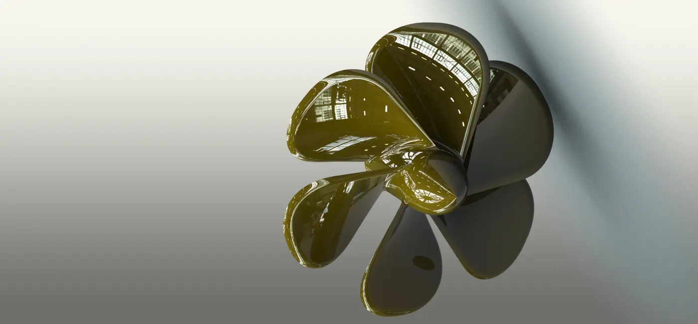
propeller
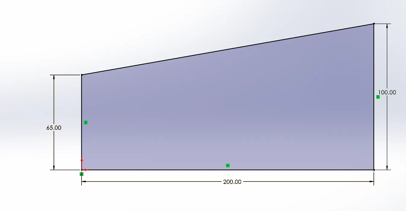
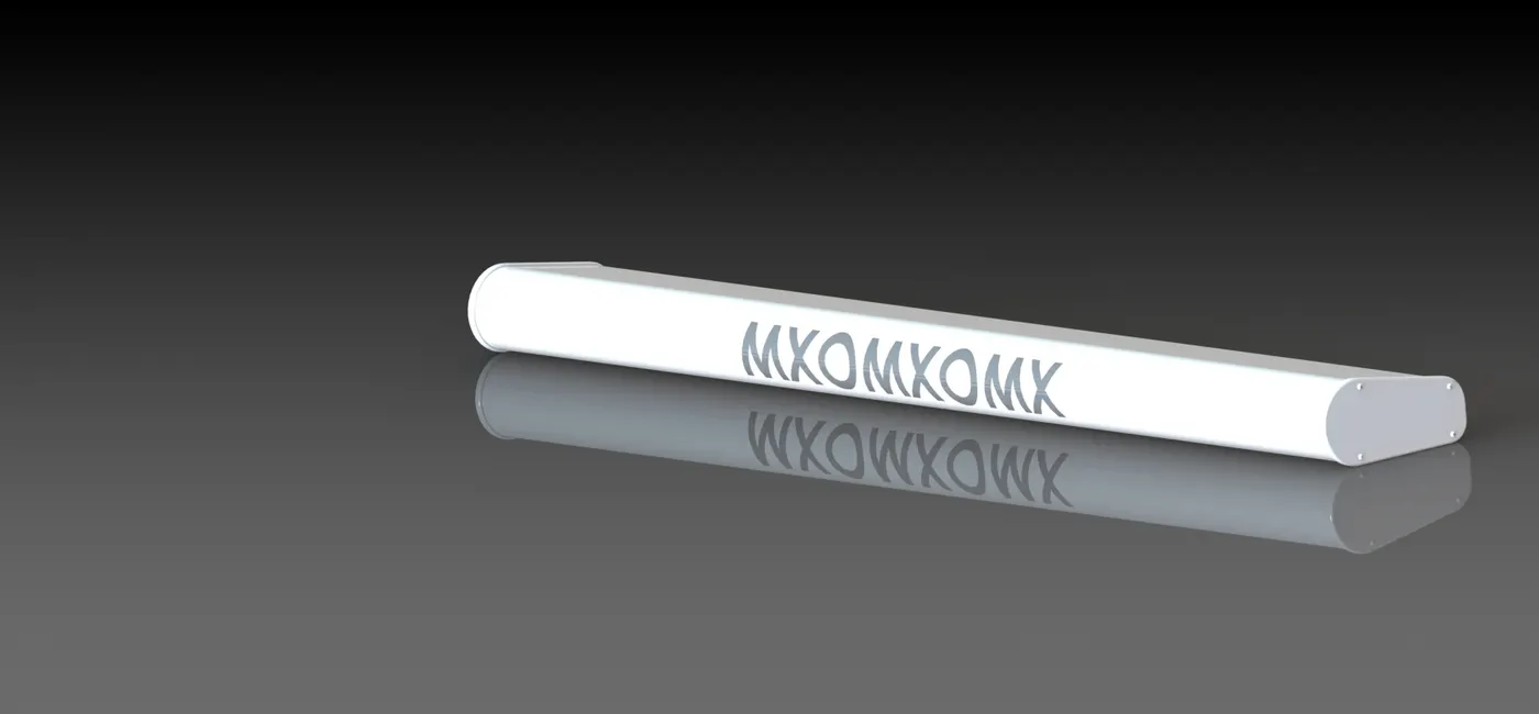
radar
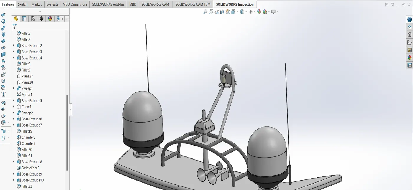
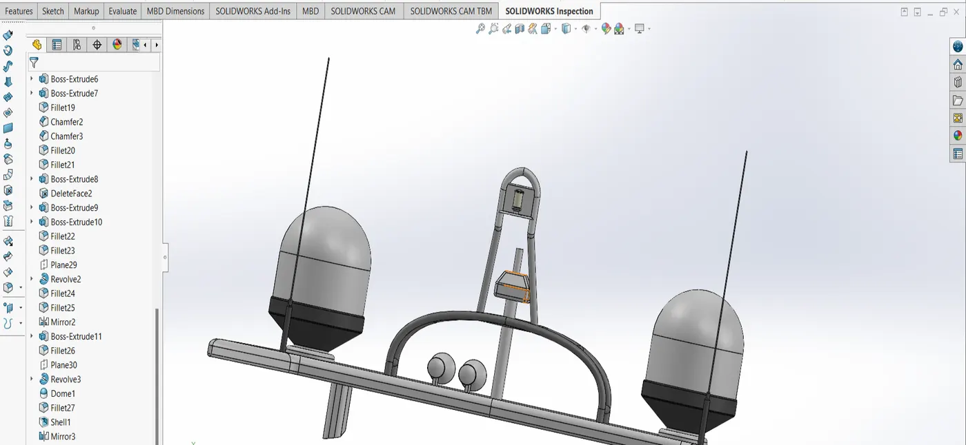
radar mast
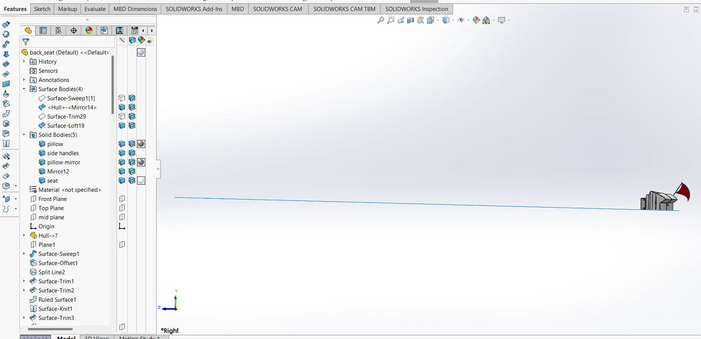
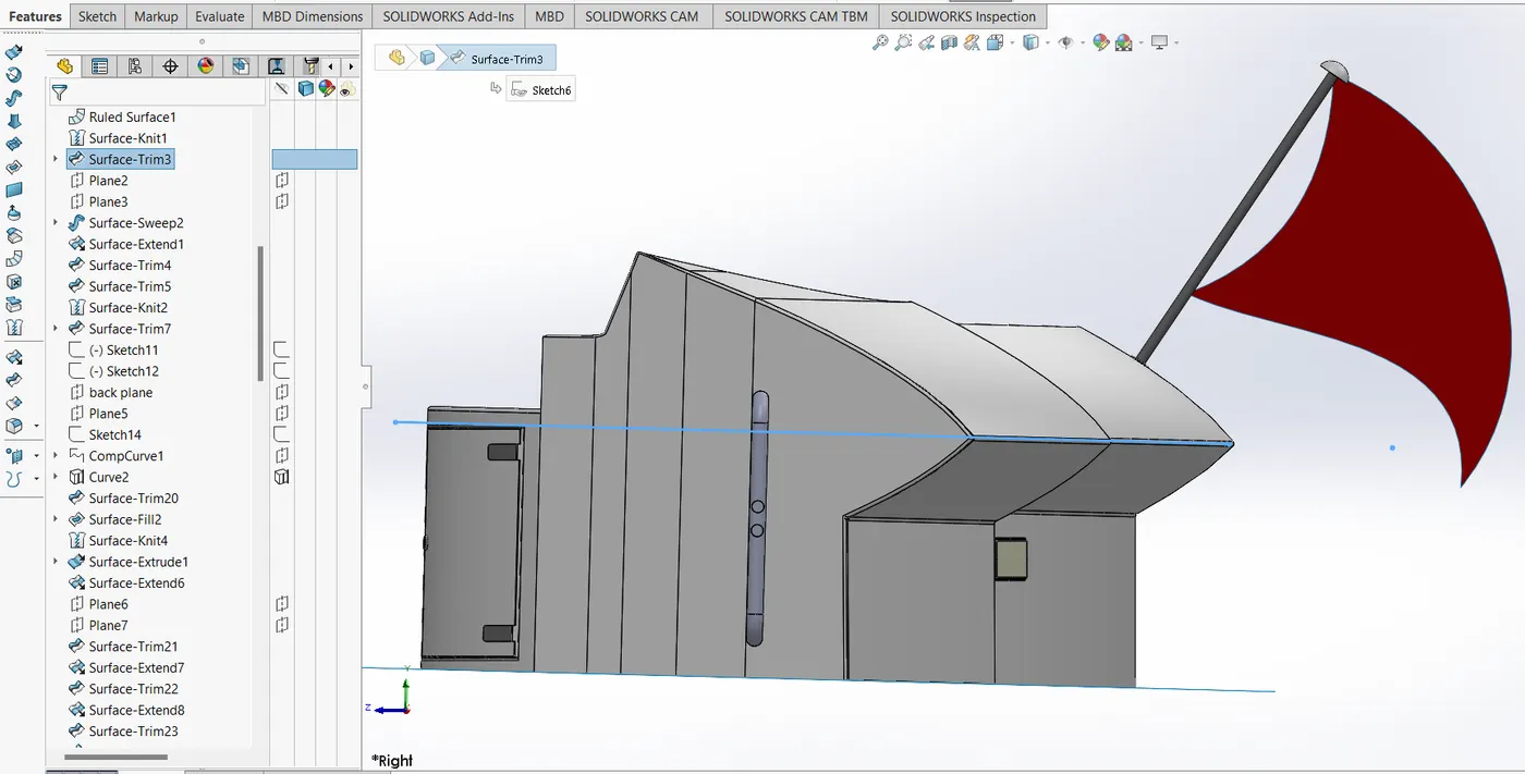
rear seats
superstructure
in this project, these parts are made separately and then assembled in the form of Yatch Assembly.
making parts would include applying all the tools in the solid and sheet models available in Solidworks.
by the end of the assembly, all the tool usage to make parts according to the PDFs shared would be aptly applied.
the following parameters would be followed:
1 All the sketches should be constrained with proper dimensional and geometrical constraints.
2 Assembly should have proper mates and appropriate appearances should be provided.
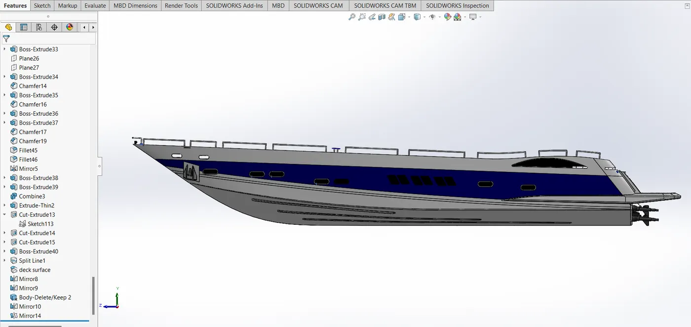
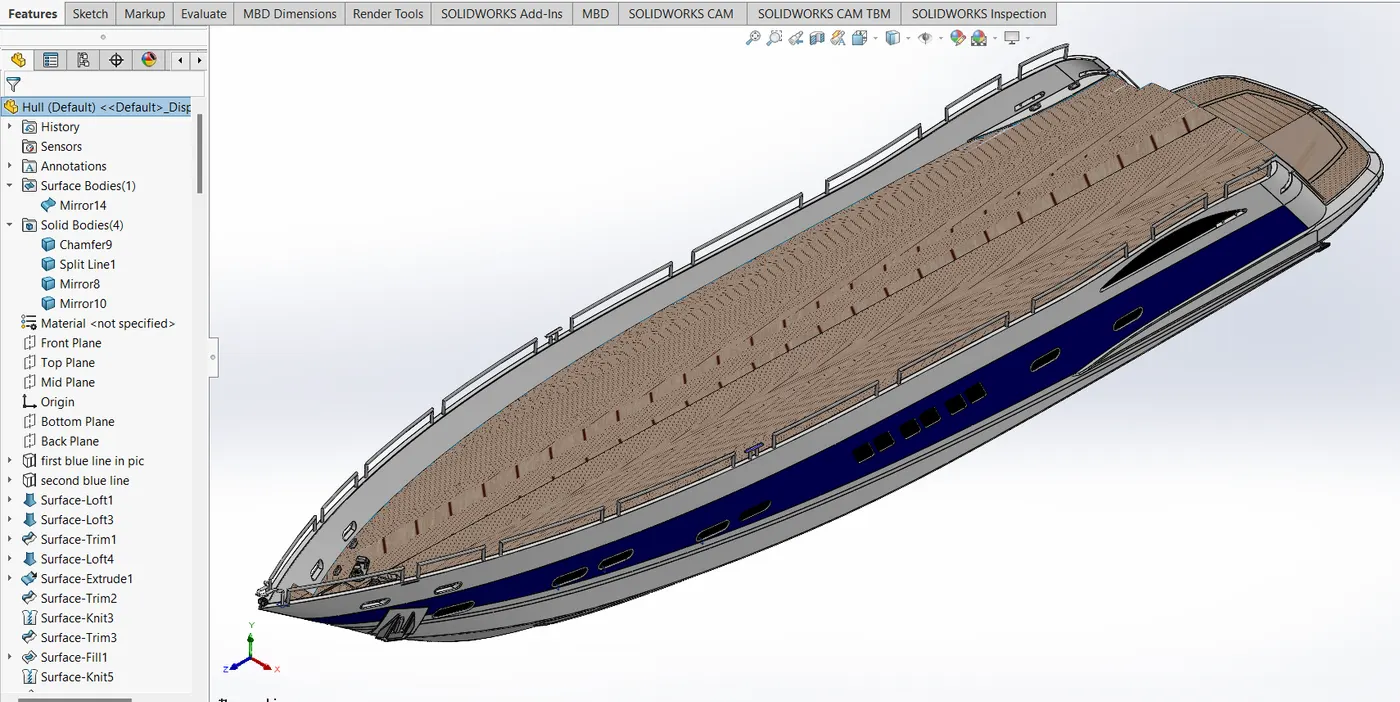
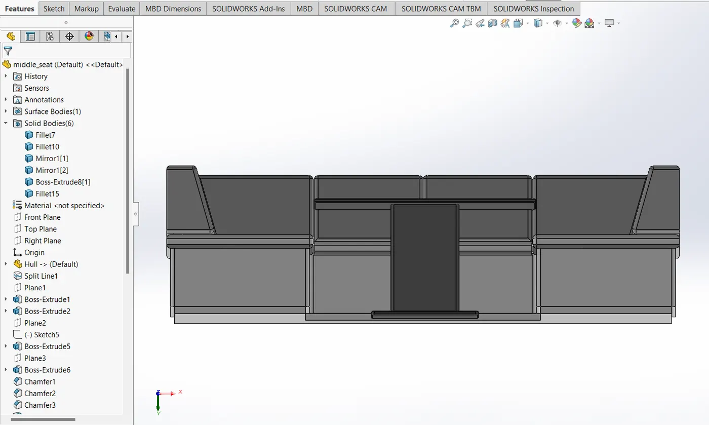
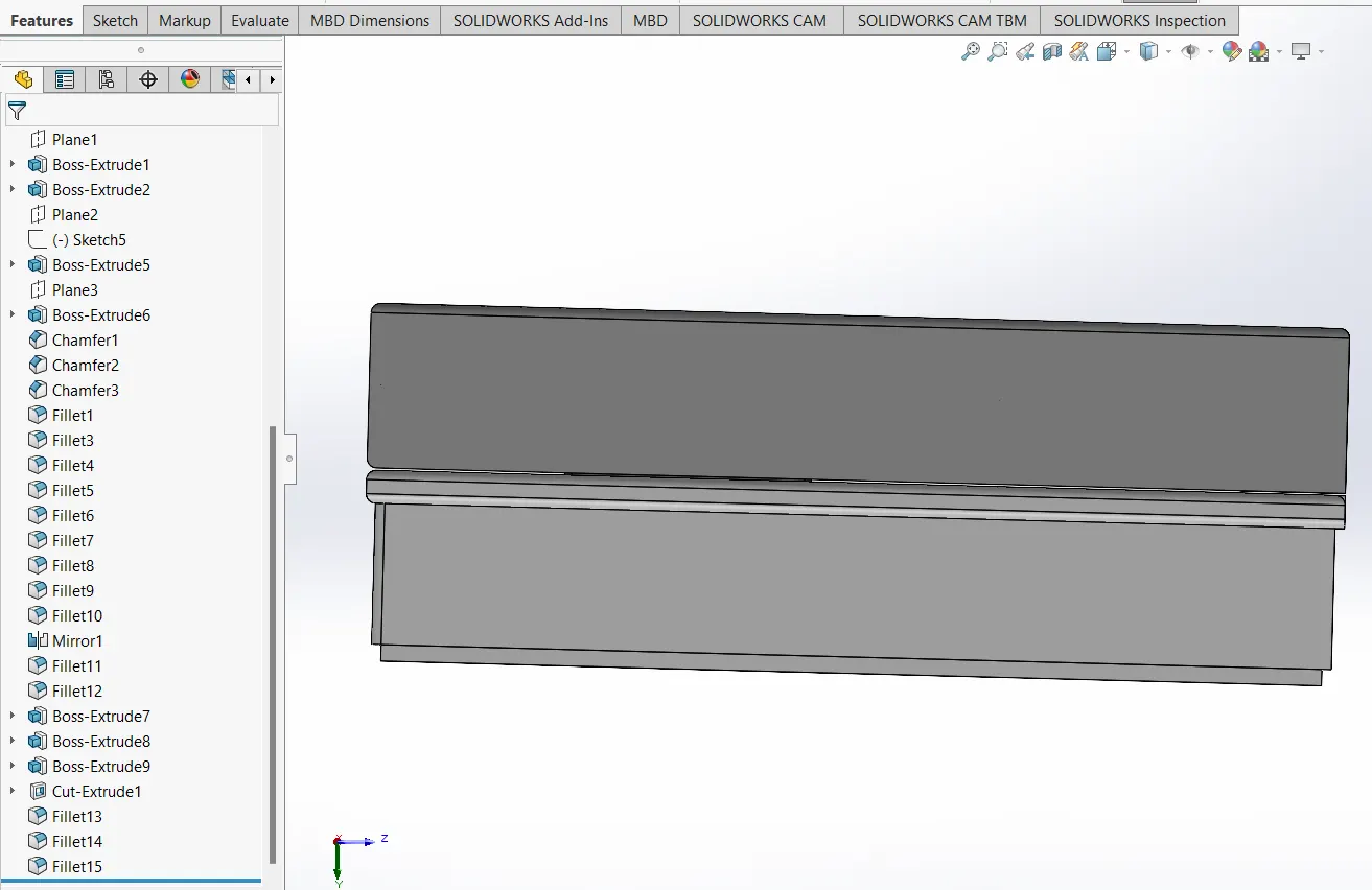
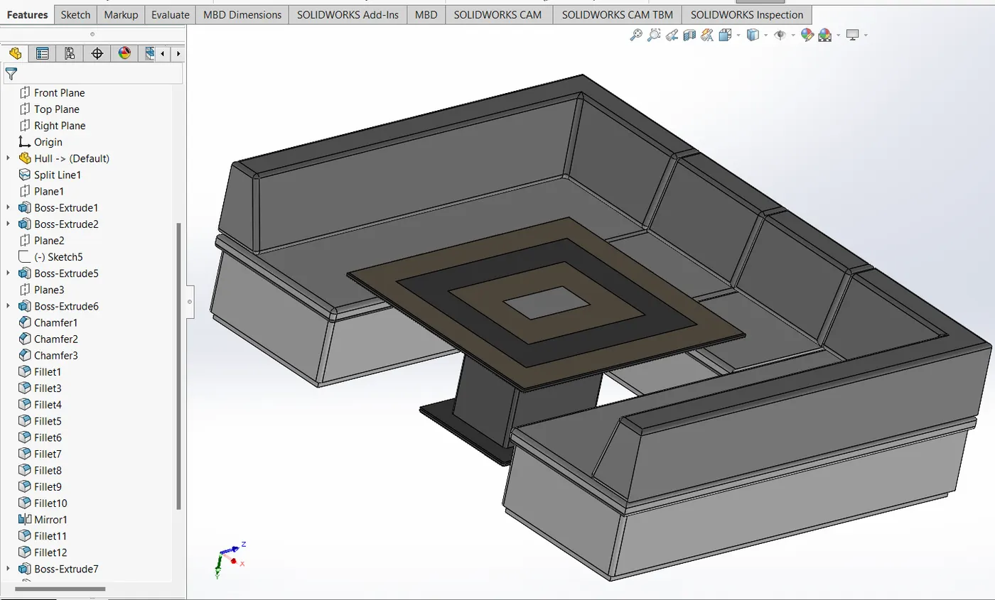
3 Insert Part Images along with expanded feature tree Part images in the Front, Side and Isometric View should be added which consists of Expanded Feature tree as well.
Explanation for Parts:
parts are supposed to be separately made and then imported in an assembly file. they are made from fully constrained sketches. surfaces are turned into solid bodies and merged to get
final part. this requires the surface to be in legitimate tolerances. these tolerances are modified according to the sheet merges and knitting. however, it is advised to keep tolerances within
a specific range to have a good quality of part build. while importing these parts in an assembly, we can import sheet surfaces, solid bodies, axis systemes etc. parts are providedcolors in RGB
color combination for the indivisual faces, or sometime whole features to stand out to help differentiate and make it more look more realistic. rhese parts are then assembled
and rendered in an assembly file. it is necessary for the parts to have good build quality fir a good overall quality of Yatch.
the parts used in the assembly are:
front seat
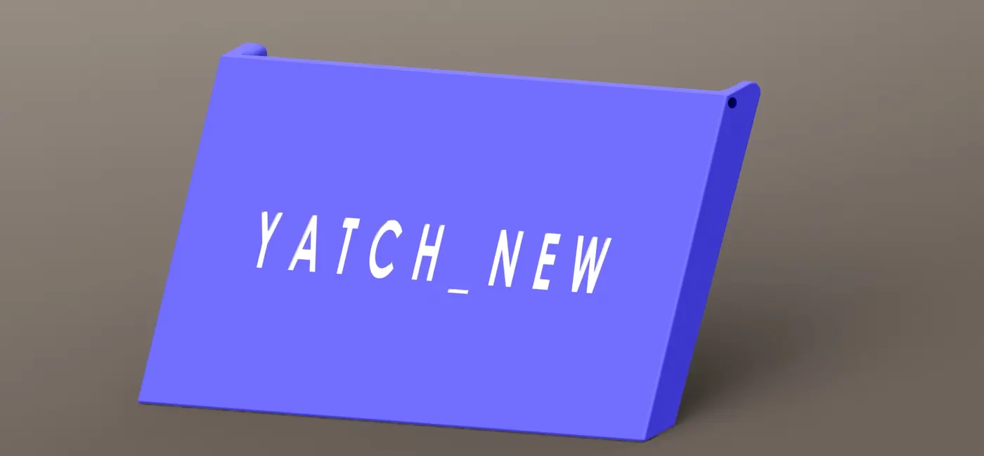
garage door
hull
middle seat
propeller
radar
radar mast
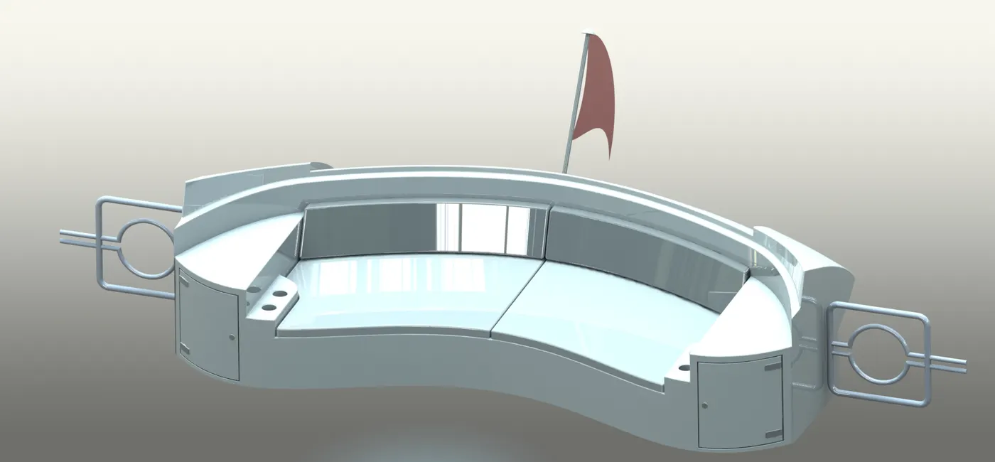
rear seat
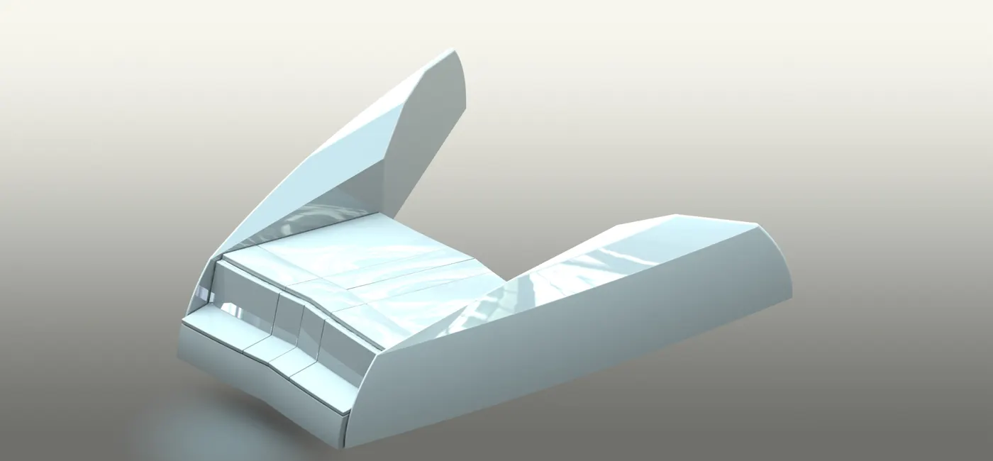
superstructure
Explanation for Assembly
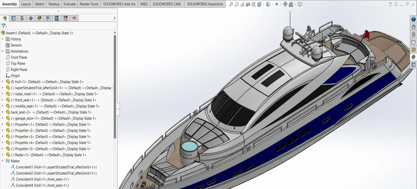
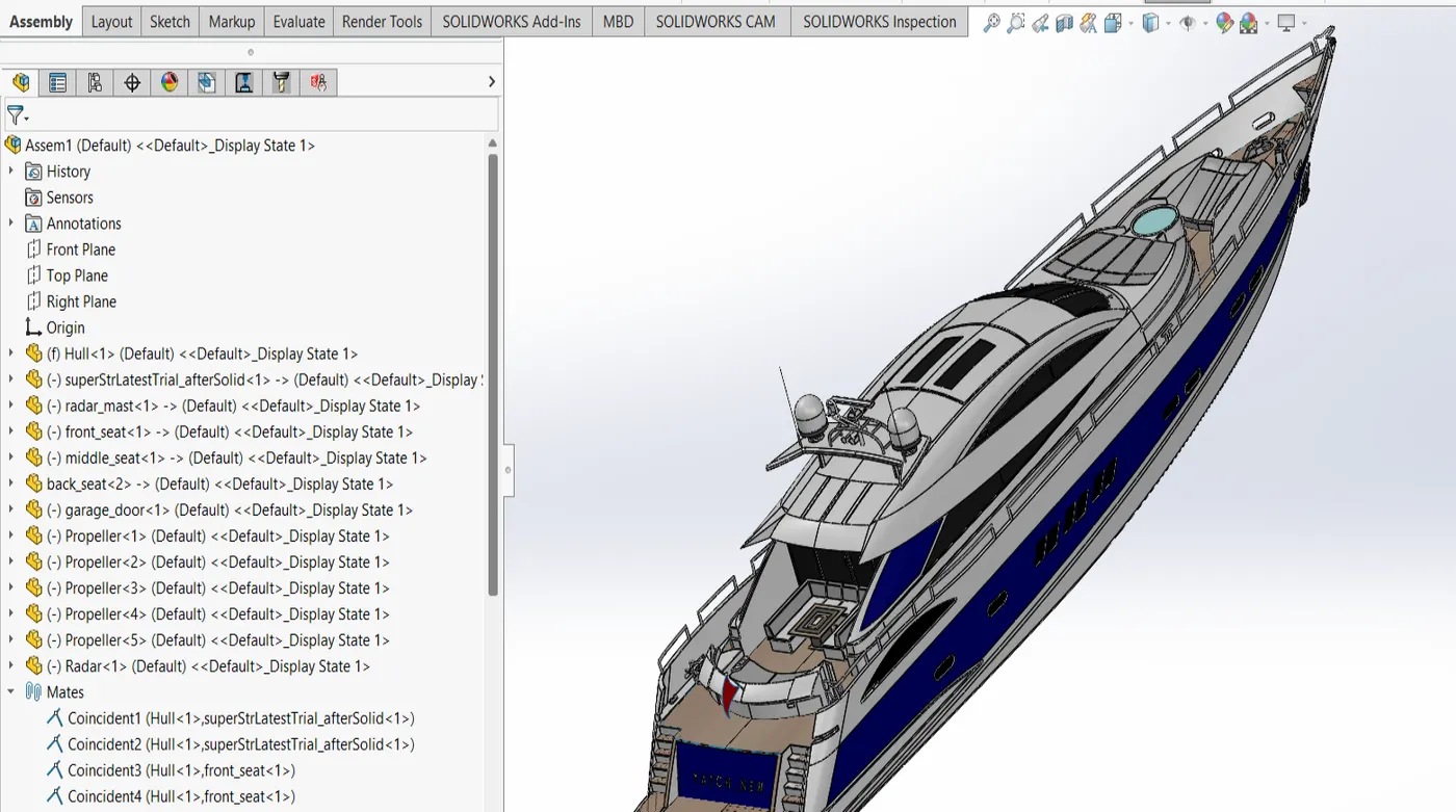
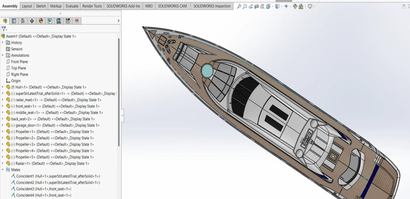
the hull is imported first. it is fixed by default. we need to align other parts with respect to the hull. next, the superstructure is imported and its mid plane is made coincident
with that of the hull. then its ottom surface is made coincident with the floor of the hull. we keep the third degree of freedom active as it needs to slide a bit and make way for the other
components to fit in. next we import, the front seats. similarly, its mid plane is made coincident with that of the hull. then its bottom surface is made coincident with the floor
of the hull. similar steps are followed for the mid chair sitting arrangement and the rear seats. the rear seats are kept at 50 mm distance from the edge of the hull. this is distance mate.
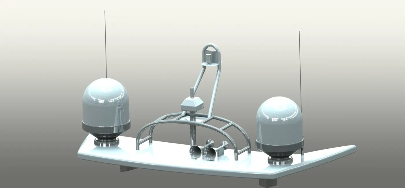
this is done from the coincident tab nevertheless. then the radar mast is imported. the same steps if mating is followed but this time it is the upper surface of the superstructure
and the lower surface of the radar mast, which are mated coincident after aligning respective mid planes. radar is mounted on the radar mastand concentric mate is applied for it to
fit in the radar mast perfectly in the slot. thej the garage door is imported and aligned with coincident mate to the mid plane with that of the hull and concentric mate to its
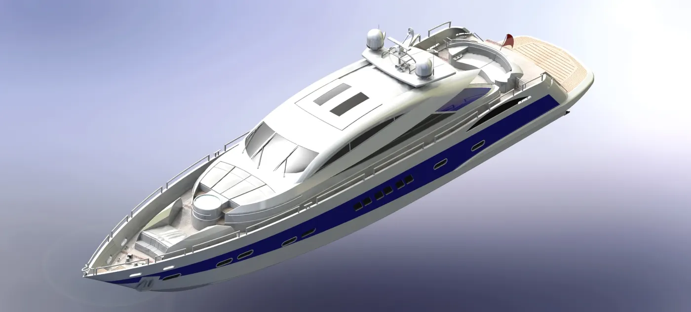
joint extensions. now we have every part we need and in an assembly form.
Explanation for Rendering
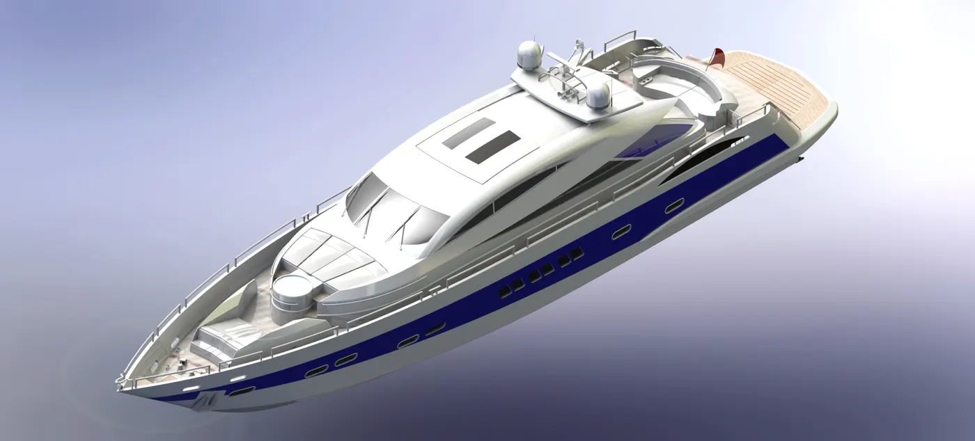
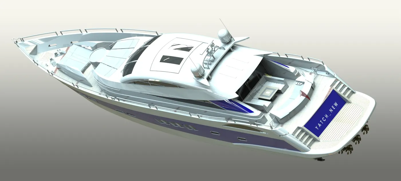
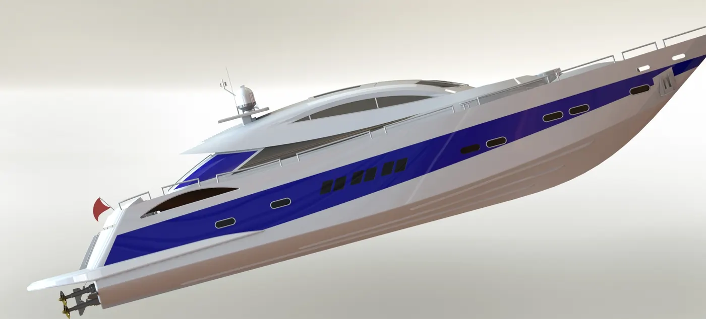
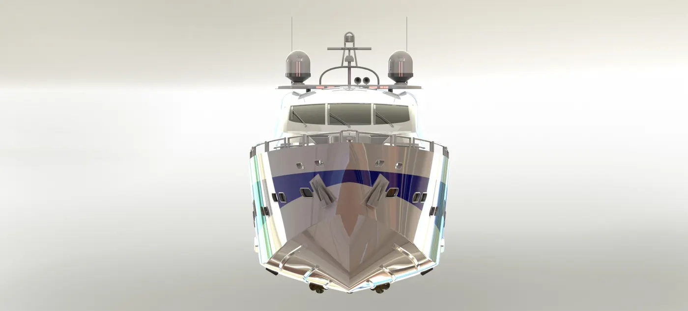
rendering can be done by choosing the scenes. theere are many scenes available in Solidworks. rendered images are attached as well.
Addition of rendered image
Design methodology / approach (To be explained with the help of Flowcharts only)
Design methodology/approach (To be explained with the help of Flowchart)
Overall flowchart -
(1)sketch - (2)part - (3)assembly - (4)render
(1)Sketch -
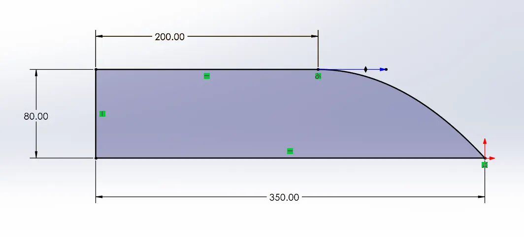
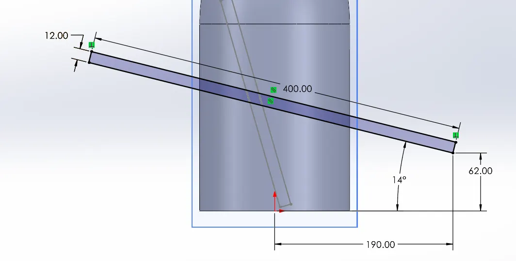
use line, circle, arc, spline, slot, trim entities, convert entities, offset entities, mirror entities, linear sketch pattern, blocks , dimension etc. to make a fully defined skectch.
(2)Part -
use features on the drawn sketches, to make a part. use features like extruded boss, revolved boss, swept boss, extruded cut, revolved cut, swept cut, fillet, pattern, mirror, reference geometry, curves, split etc. to make parts.
(3)Assembly -
import parts one by one in an assembly file and add constraints over them to align them into an assembly. use mates like coincident, tangent, distance, limit angle, width, parallel, angle, concentric etc. to align and fix parts. mirror them if necessary.
(4) render -
we use solidworks add-in Photo View 360 to render the image. when we want to see how the CAD model looks in real life with all the nuances of light playing on its surface, we go to render a model.
there are numerous setting options in rendering. you can add decals, which can be seen in the models attached with this report as well. appearances can be edited. so can the scene in which the CAD model is to be placed.
we see integrated previews to have a wuick look on how the model behaves in conditions to lighting adn overall look. preview windows does a similar job. final render shows us how the image is going to be after wverthing is kept in check.
when we want to select a specific region to render, we use render region option. ther are a lot of choices offered by SOlidworks to select the lighting conditions, camera positions, adding decals on thg decals on the parts etc.
there is an Options setting where we choose output image size, render quality - good, best, maximum; bool options, contour/cartoon rendering, direct caustics, network rendering and more.
if the render is expected to take a lot of time, we can schedule it. also recalling last render is one of useful options to play with.
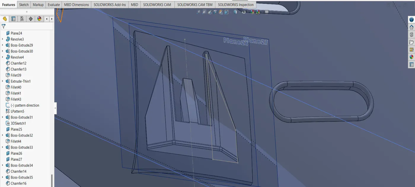
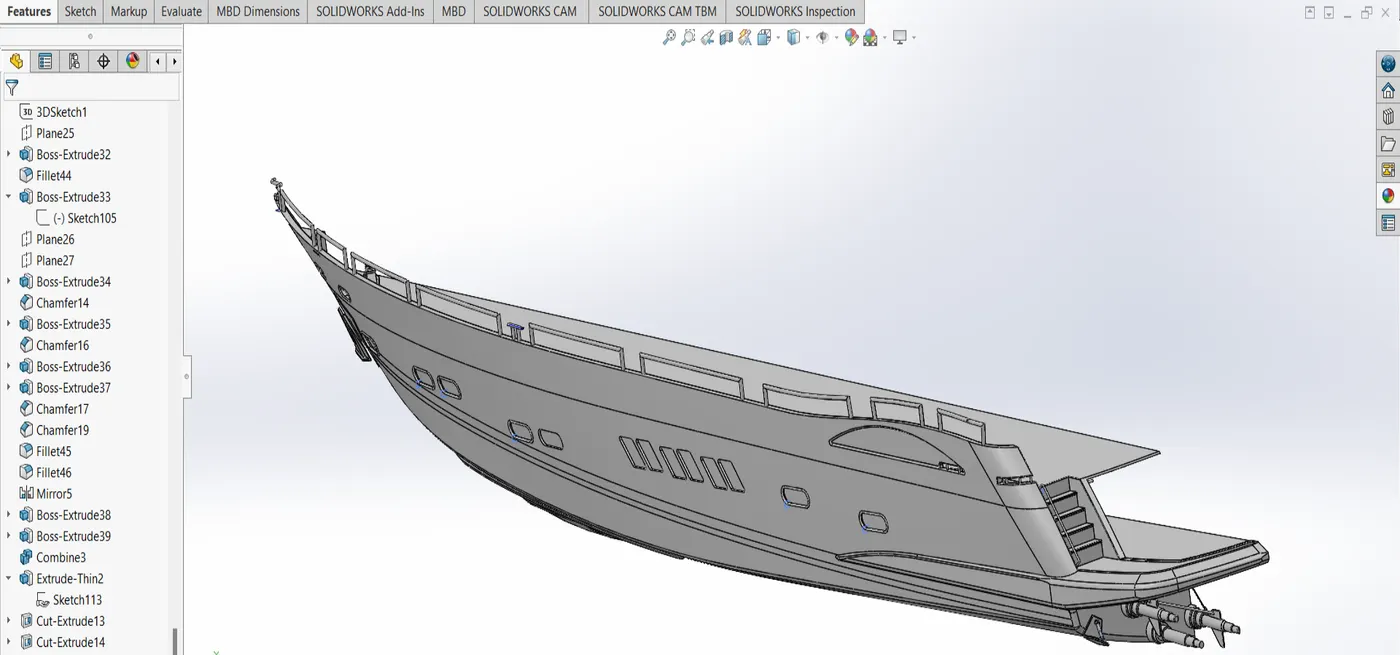
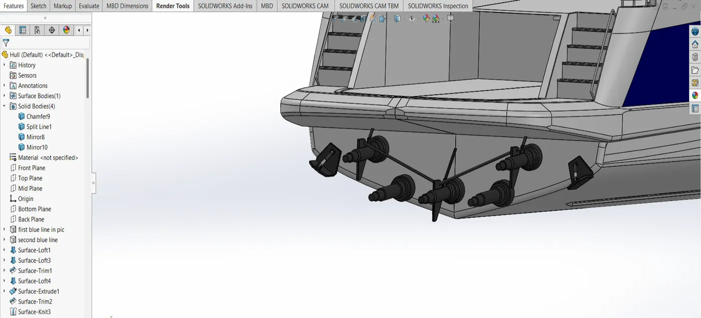
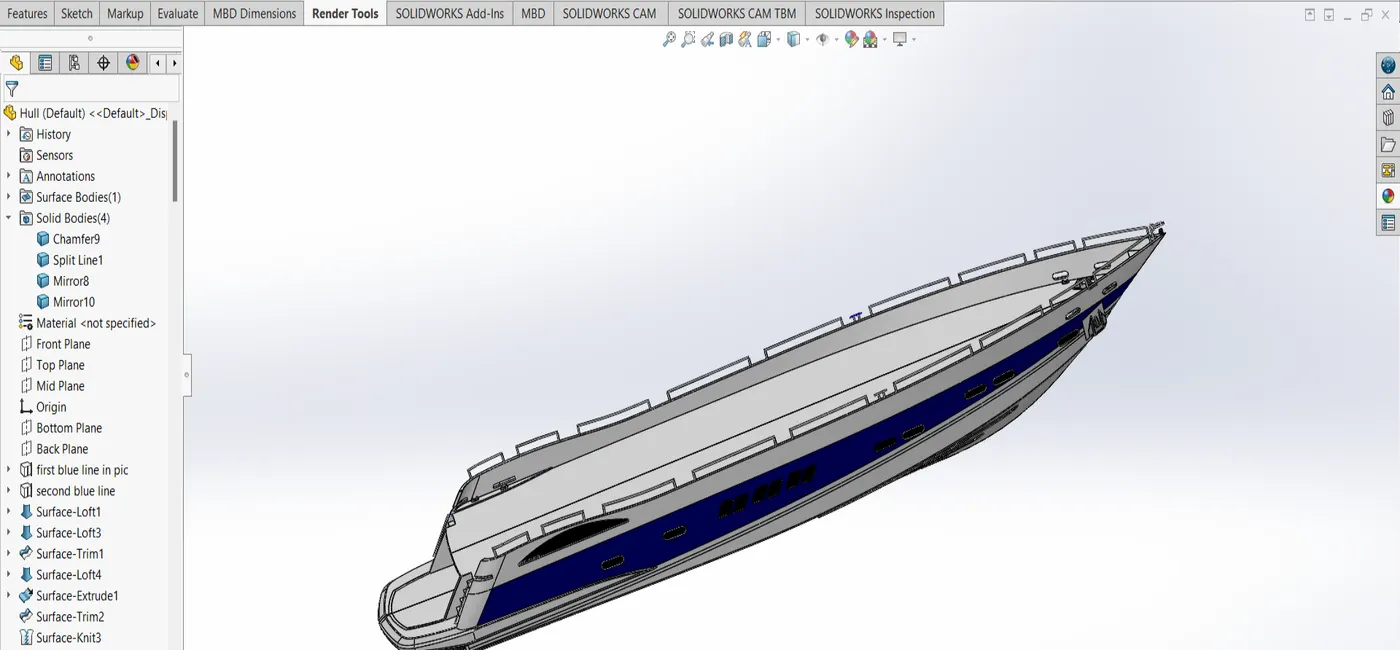
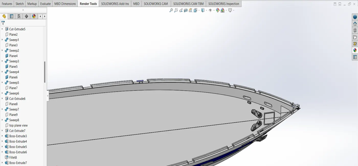
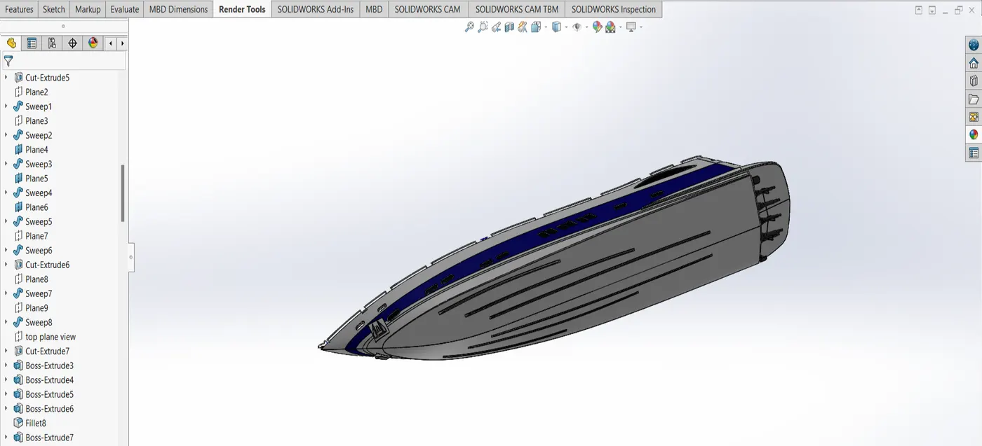
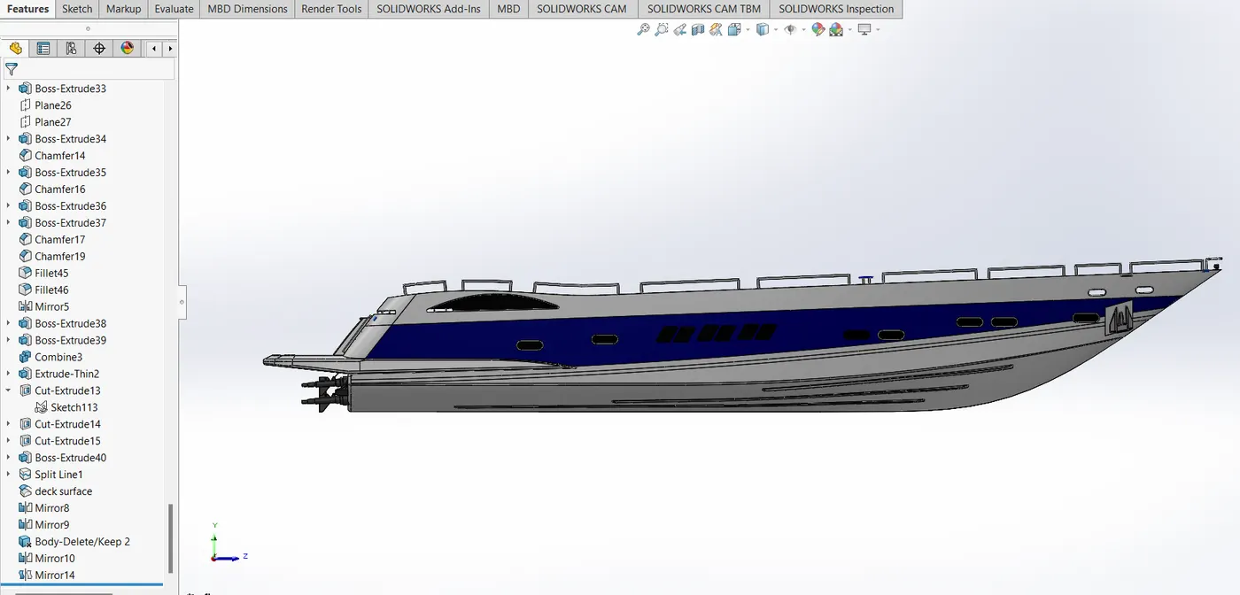
Description (Need to explain tools/ Features used while designing) along with the images of Part files.
features used -
surface loft - used to create a surface providing start surface, end surface and guide curves.
surface extrude - extrudes a surface in a direction specified by the user.
surface trim - trims the surface using tool and target. tool can be edge, surface or a user created curve.
surface knit - knits surfaces according to the tolerances provided. merges multiple surface identities into one.
surface fill - fills the surface void specified by user by selecting the required edges.
shell - used to create a shell in a solid surface when provided with thickness.
reference plane - plane created using 3 inputs according to user requirement.
projected curves - two curves behave as a single independent curve when projected. start and end constrains should be same.
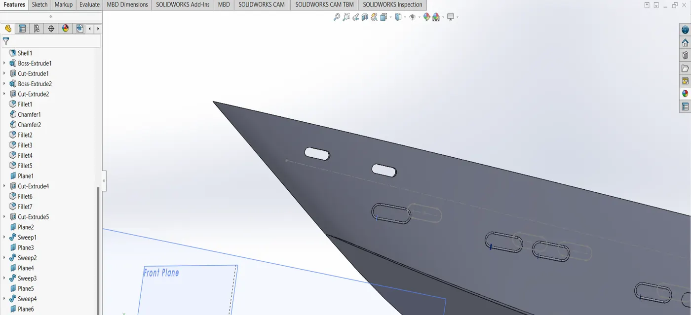
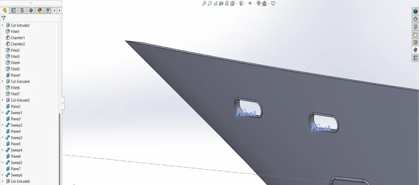
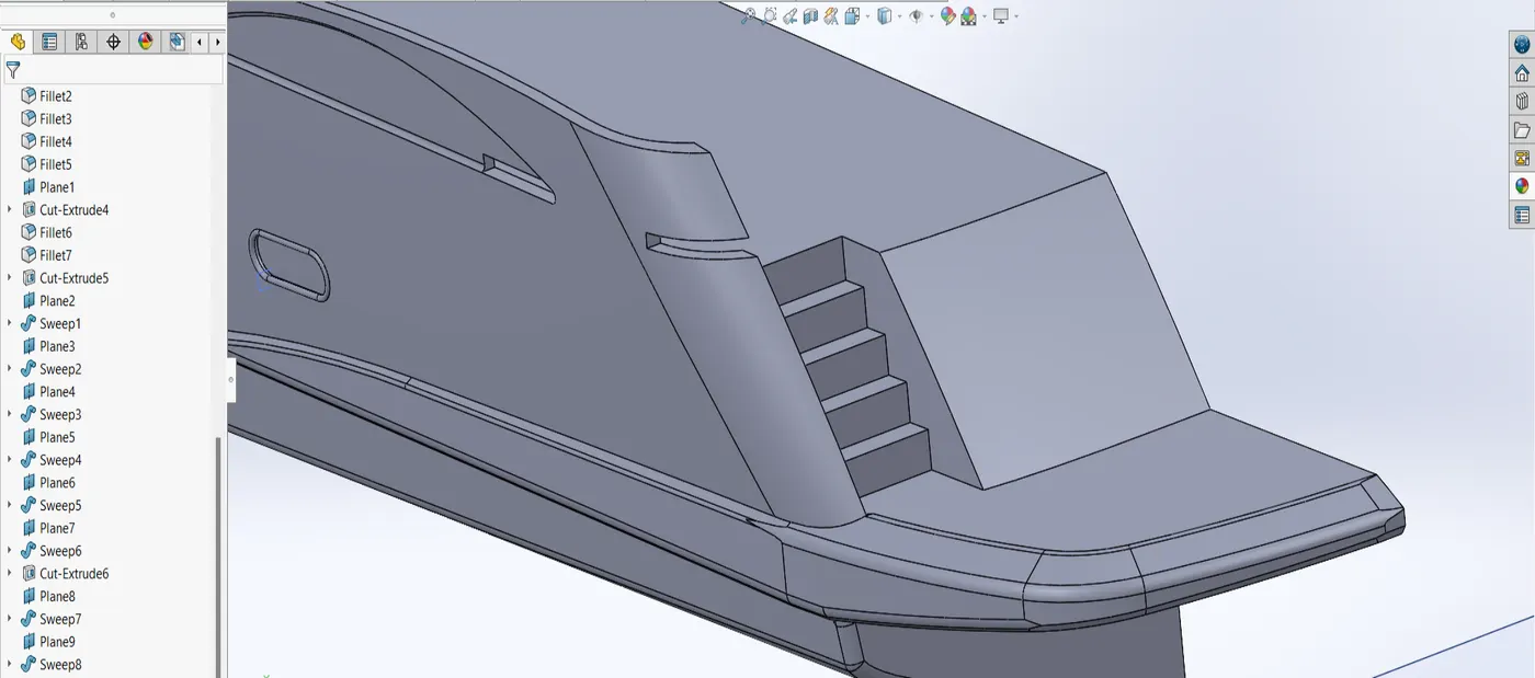
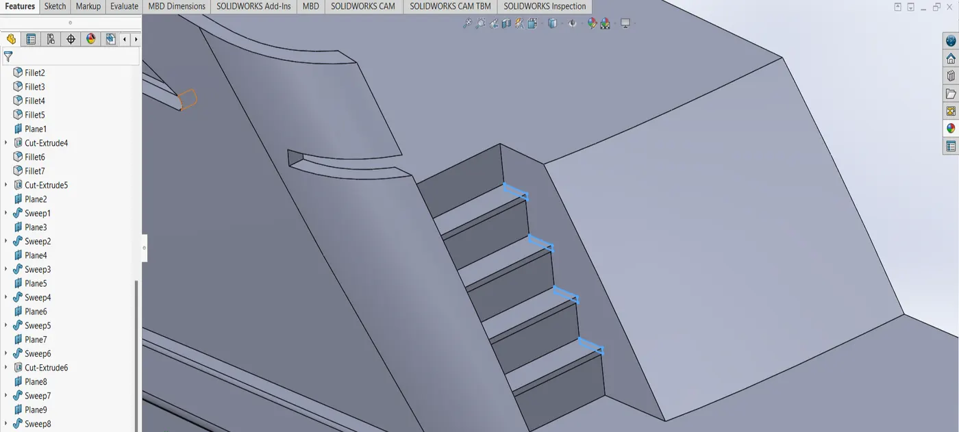
sweep - sweeps a curve in a path specified by a different one. used to create railings.
revolve - revolves a given sketch wrt some axis as specified by the user.
dome - creates a dome on a specified surface with input radius.
helix/spiral - creates a helix or spiral with a given radius and other parameters as specified by the user.
delete face - deletes a face, can delete adn patch or delete and tangent fill.
boundary surface - creates a surface when provided with a closed boundary.
mirror - mirrors features and sketches.
split line - inputs surface and a plane/reference to split the surface with.
3D sketch - creates a 3D sketch. requires no plane.
convert entities - if in a sketch, takes reference of every geometry available and user specified geometry as an active reference in current sketch.
offset entities - offsets geometric entities like faces, edges etc. according to user preference.
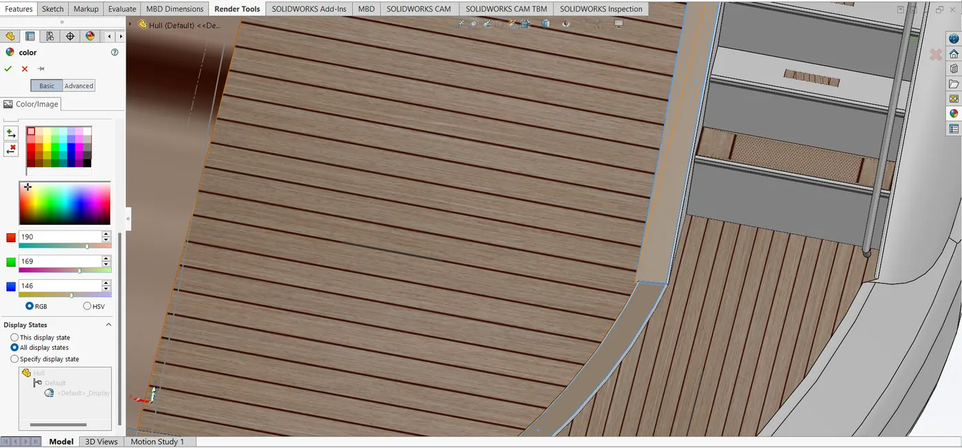
Appearances: defines visual properties of the model including colour and texture. they do not affect physical properties which are defined by materials.
every material is a assigned a default appearance.
Boss Extrude: extrude sketch from plane.
Extrude cut: cut a solid using a sketch.
Fillet: applied on sharp edges to make them smooth applying fillet radius.
Lofted Boss/Base: feature used to achieve Complex Shapes. interpolates surfaces between various cross-sections of a model .These cross-sections can be sketches ,faces ,or edges.
Split: split single solid part into two solid parts with help of two or more parts.
Dome: make dome shaped extrude including elliptical dome and other options.
Shell: make to solid hollow part.
Combine: integrate two or more solid parts which intersect each other.
Chamfer: make a sharp edge or corner slightly tapered.
Linear Pattern: creats pattern in a single direction specified.
curve Driven Pattern: pattern is amde with input as curve.
Circular pattern : pattern is made in a circular orientation. inputs could be radius and number of instances.
Revolve boss base: solid is made from a sketch, as a result of revolve.
Revolve cut: a solid is cut from a revolved sketch.
Sweep: This feature is used to sweep any kind of fully defined sketch along a the path.
Loft -. Loft surface is used to make loft in between two profiles along with guide path.
Knit surface - Knit surface is used to knit the two free edges or open edges of the surfaces together. it reduces the gap between the two edges of the surface.
Surface Trim: used to cut away material from a surface.
Projection curve: two different curves in 3D can be combined into one resultant cureve using this.
Blocks- readily available redundant sketches used for reference.
Trim entities : it is used to trim the unwanted lines or extended entities in the sketch.
Appearances :An appearance def ines visual properties of the model including colour and texture. Appearances do
not affect physical properties which are defined by materials . every material is a assigned a default appearance.
front seat
 g
g
garage door
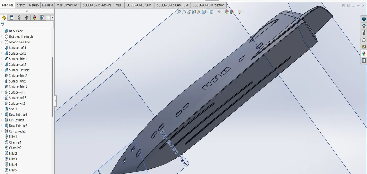
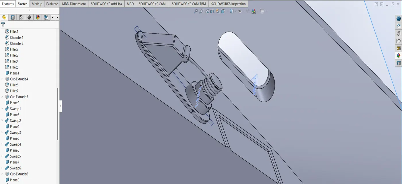
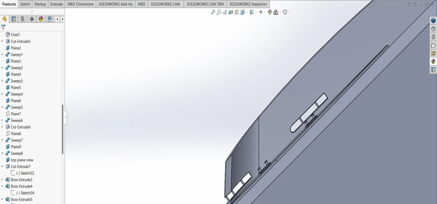
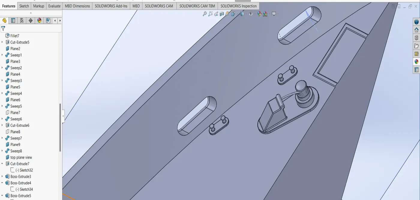
hull
 m
m
 i
i
 d
d
 d
d
 l
l
 e
e
 e
e
 a
a
 t
t
 p
p
 r
r
 o
o
p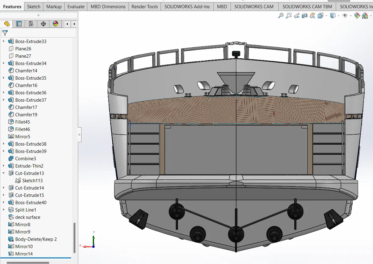 e
e
 l
l
 l
l
middle seat
propeller

 r
r
 a
a
radar
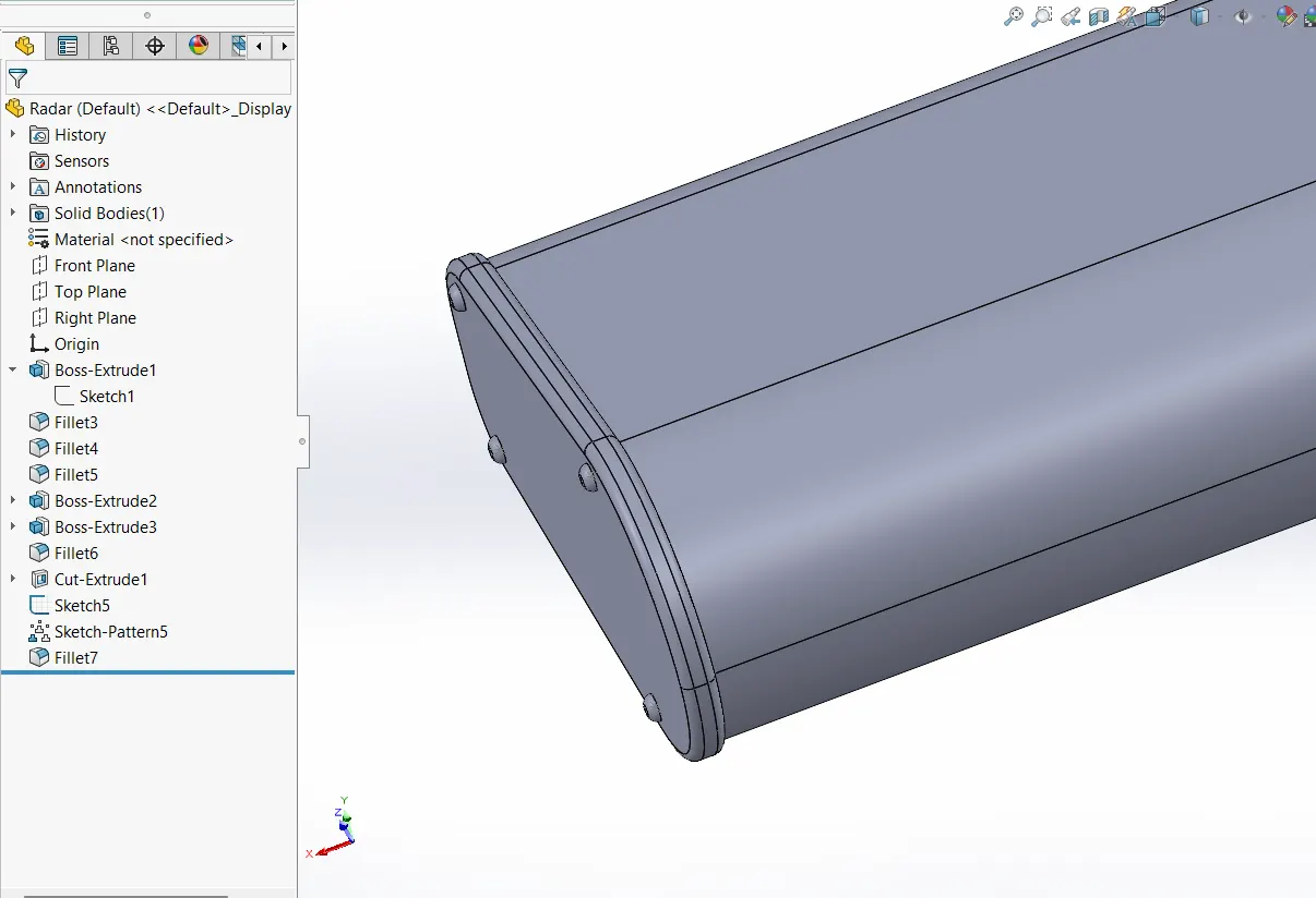
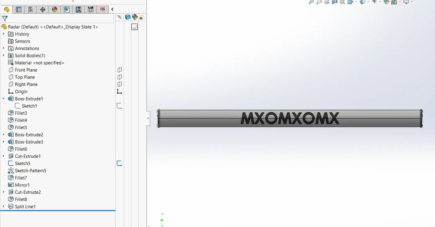
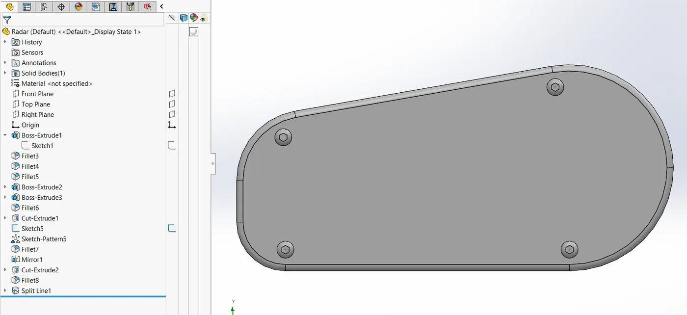
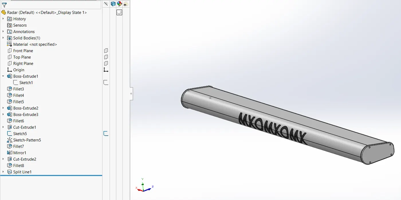
radar mast
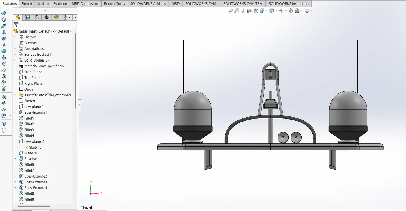
rear seats
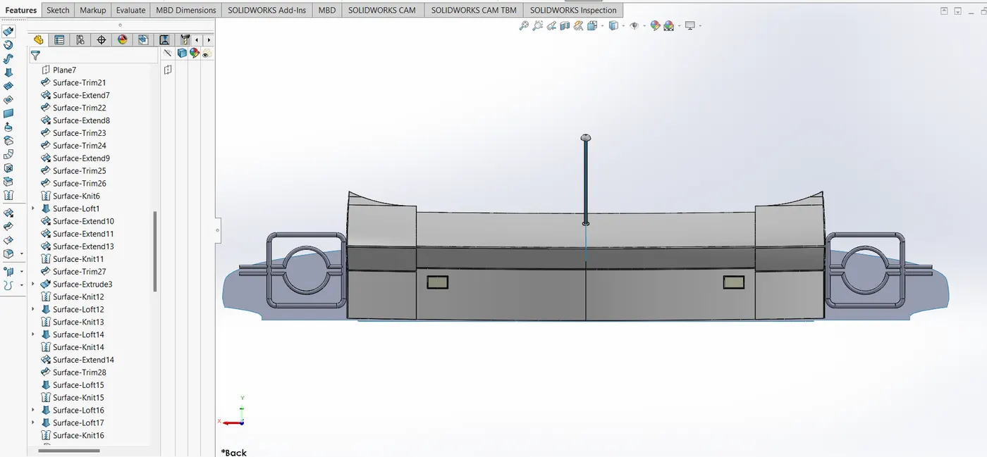
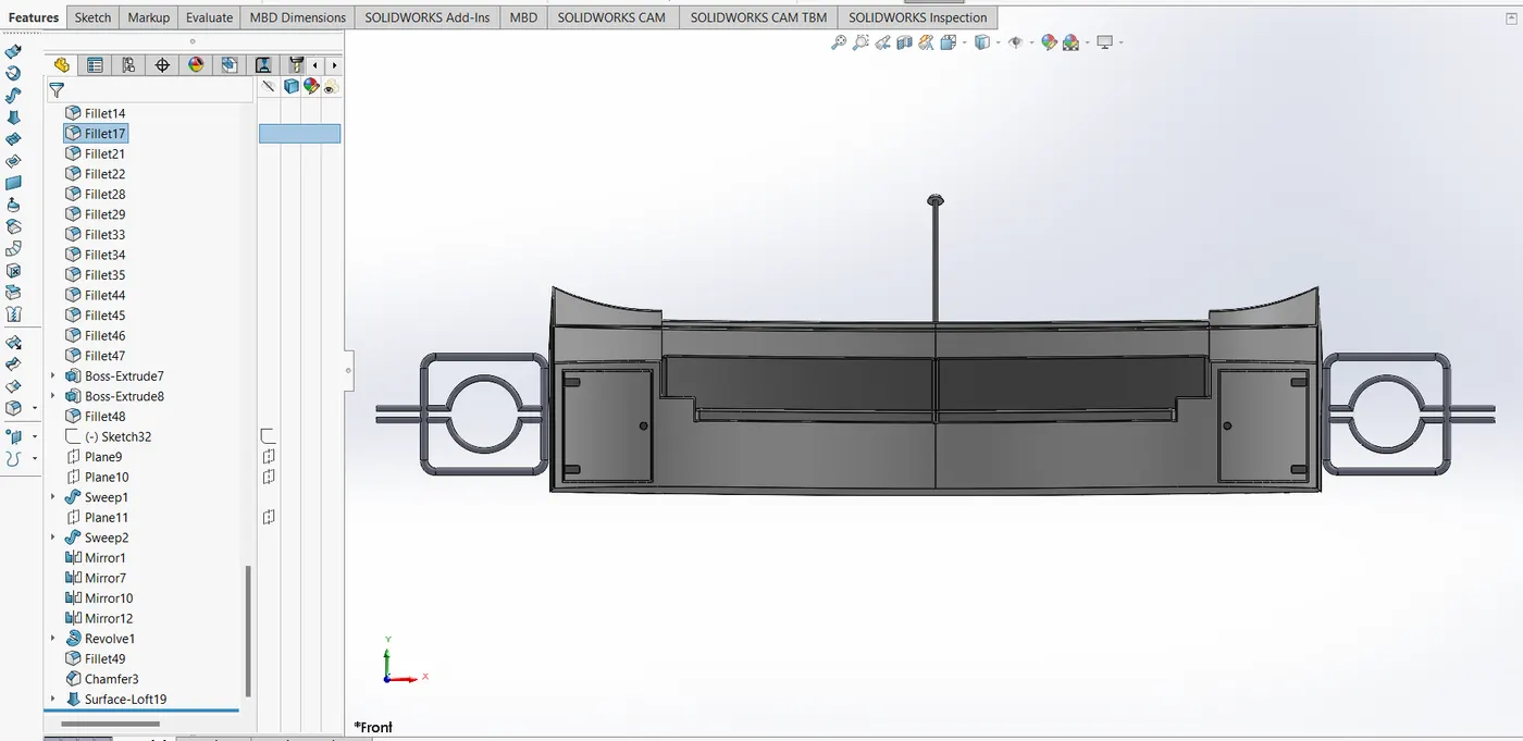
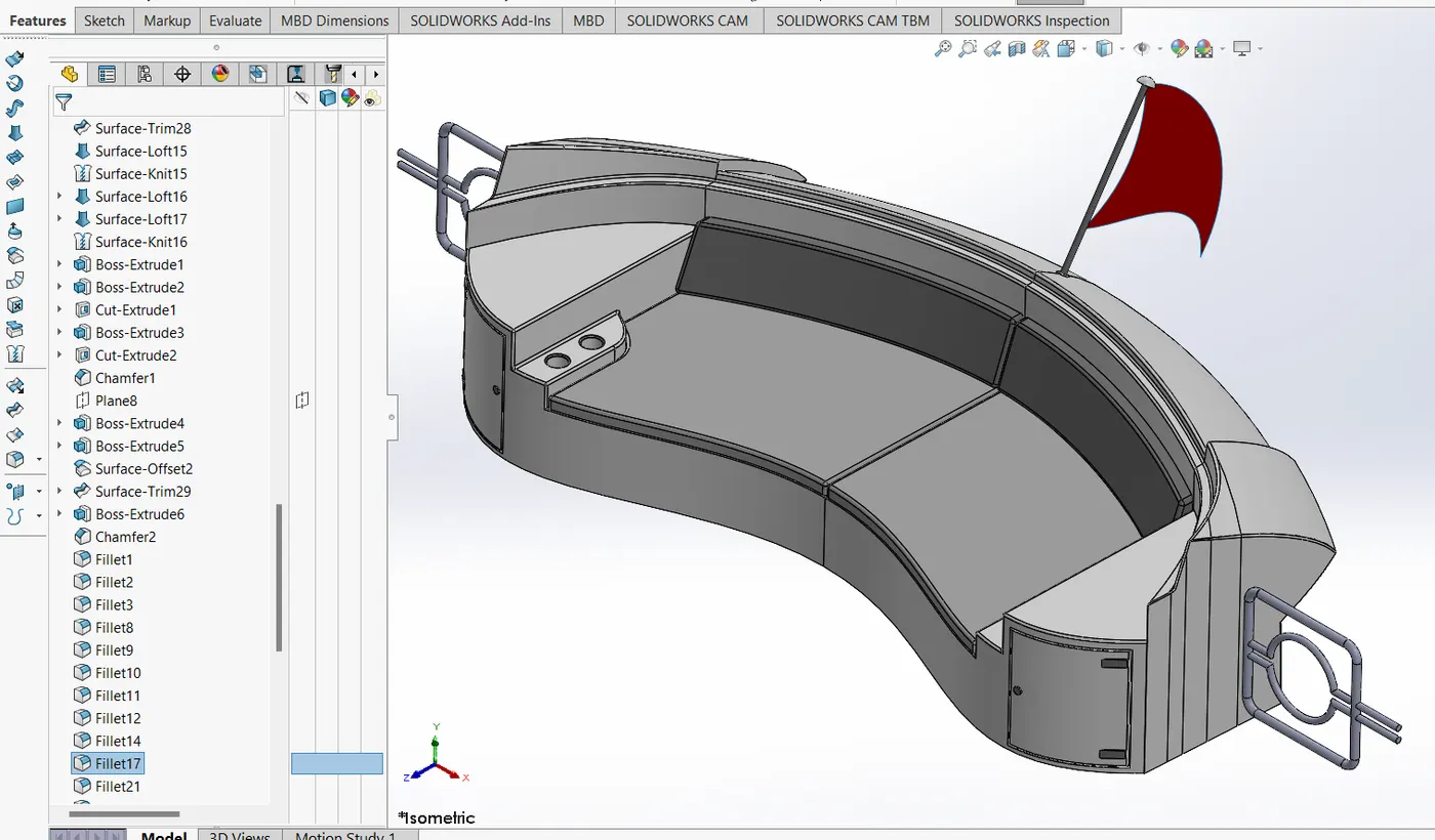
superstructure
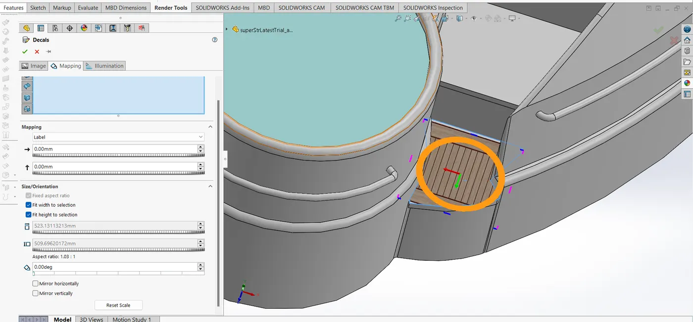
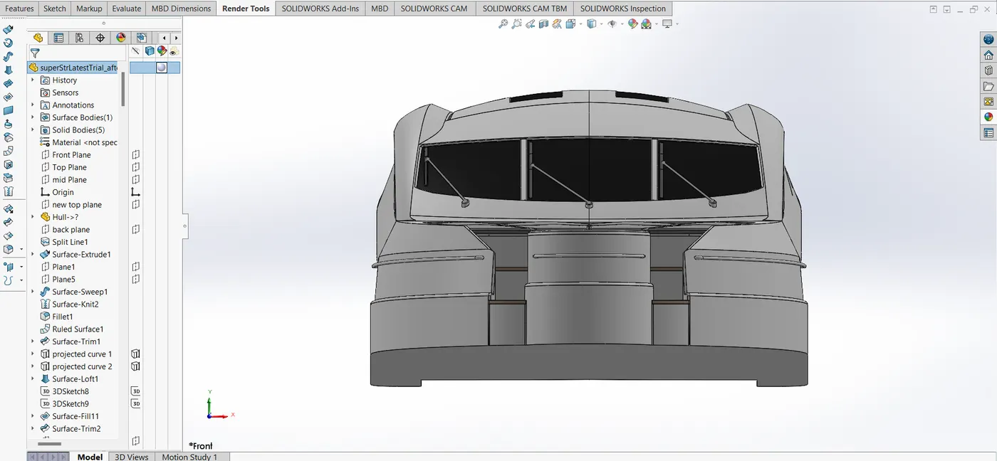
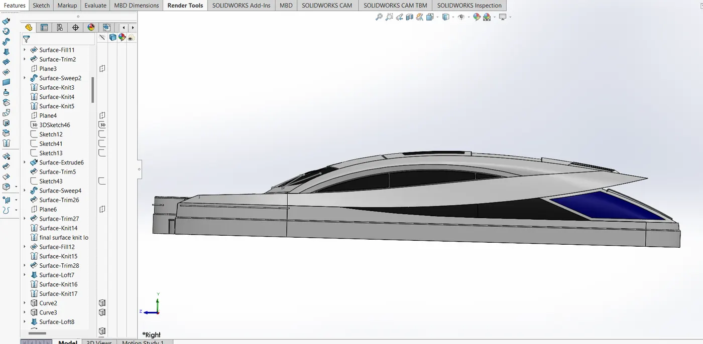
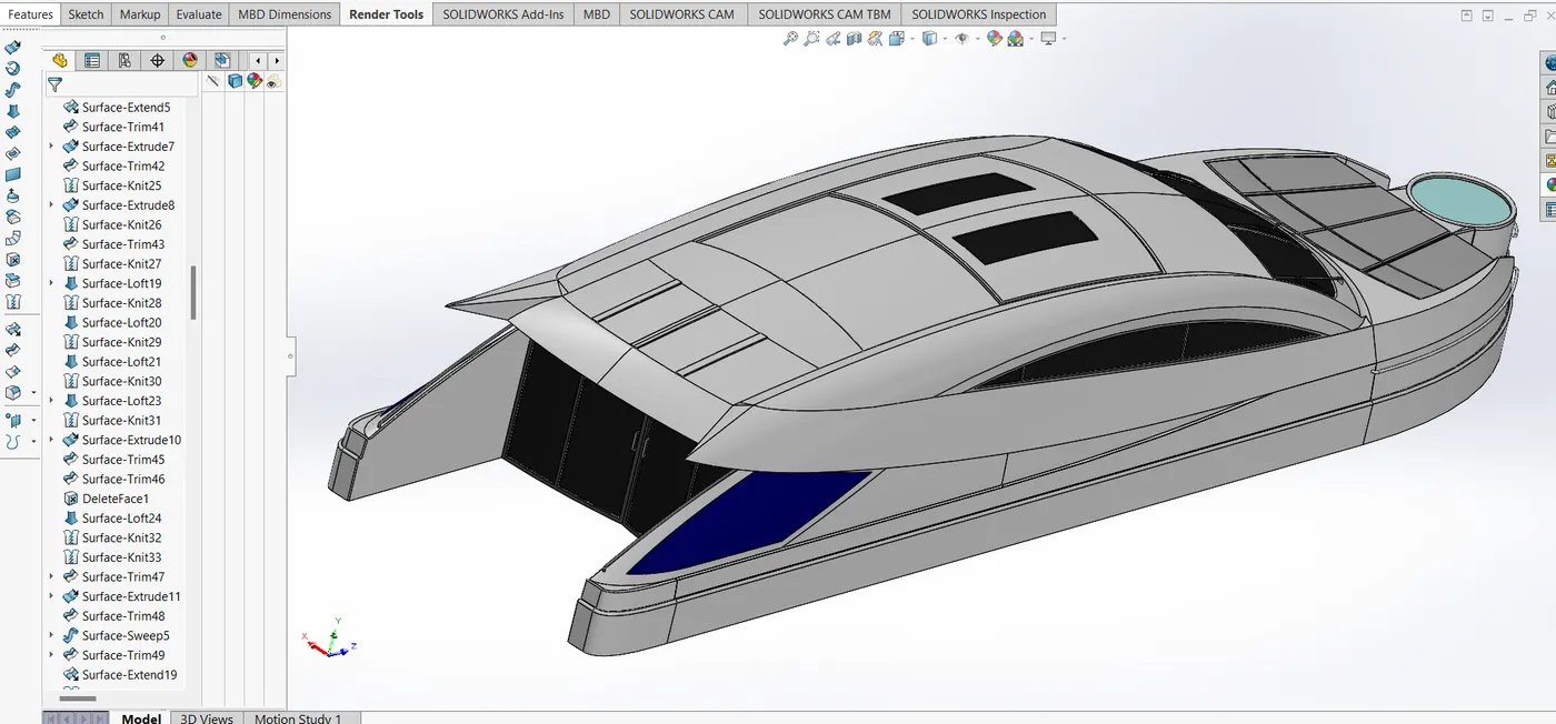
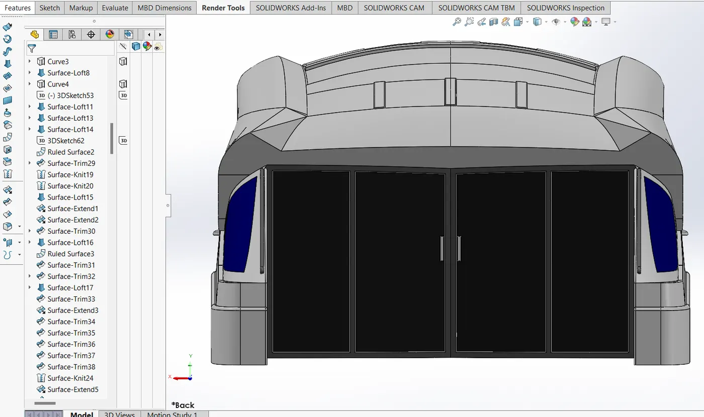
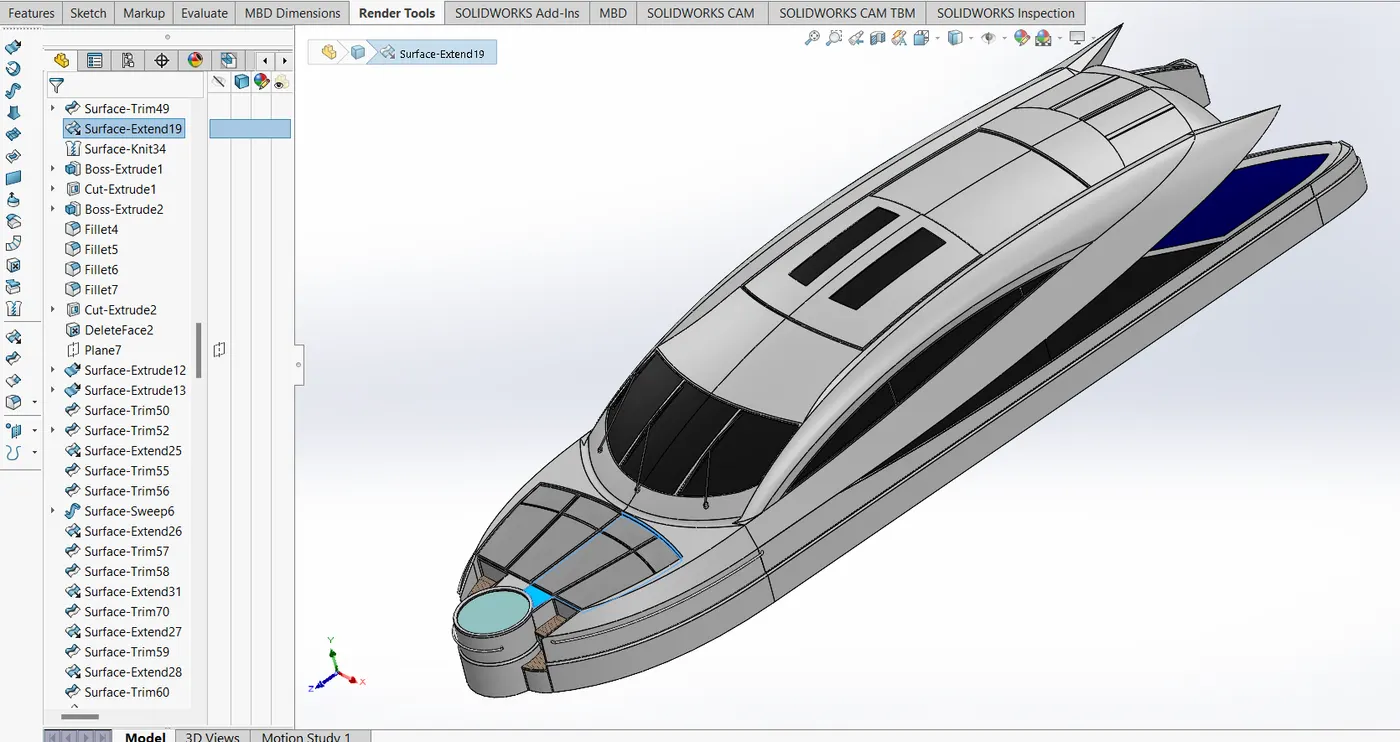
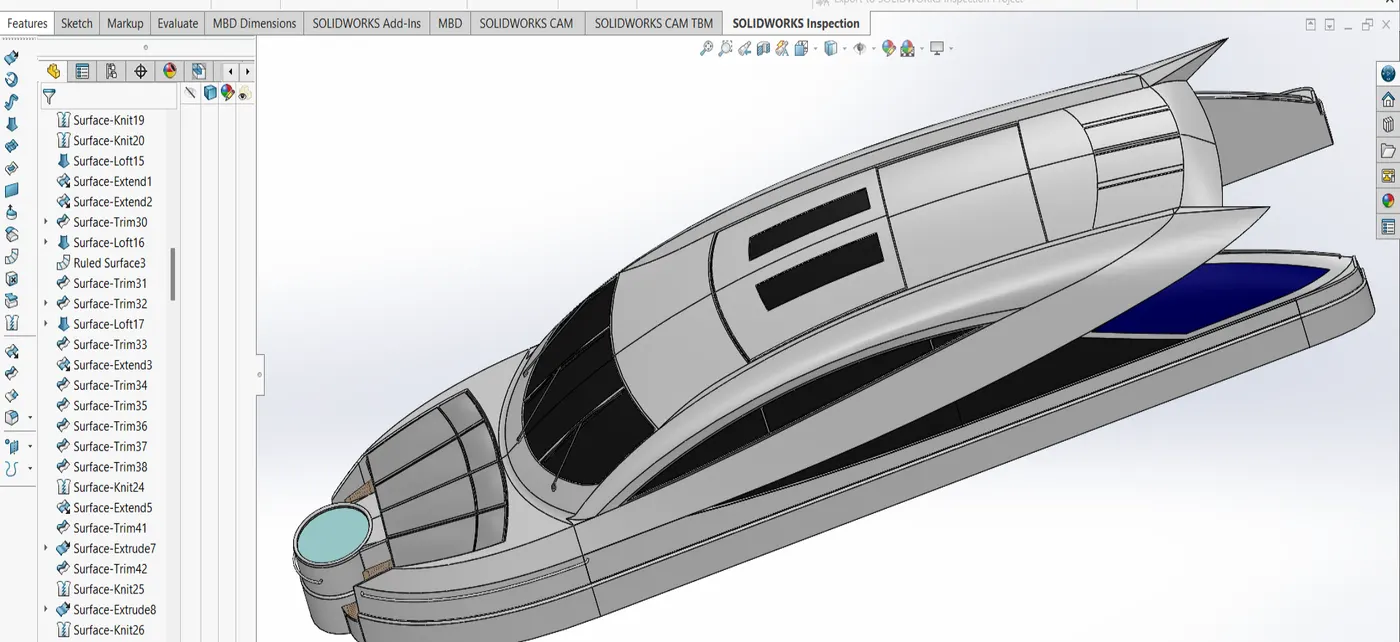
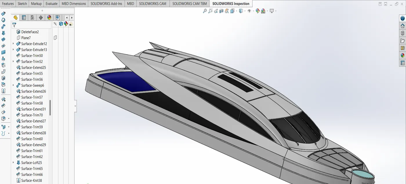
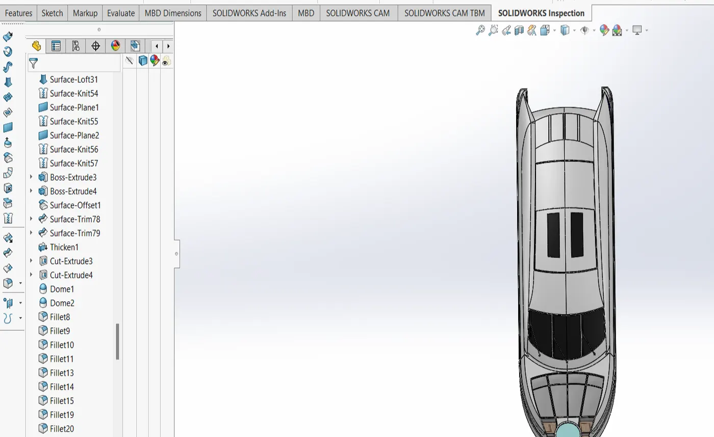
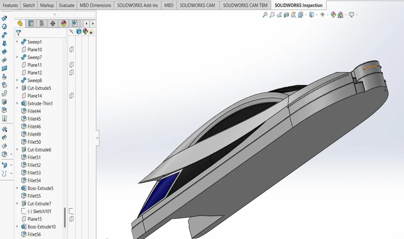

Upload a min of five screenshots of Assembly Model in the report. (For eg:-Front View, Side View, Isometric View, Camera Setup View and the Top View)
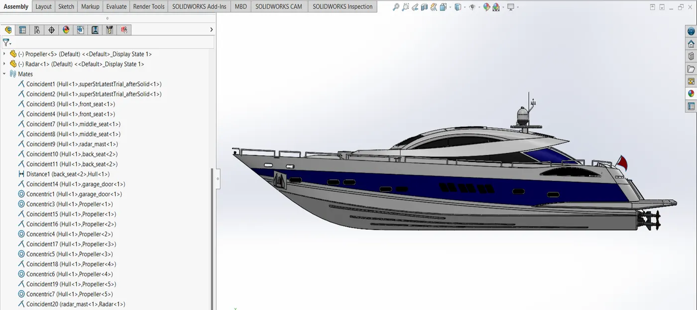
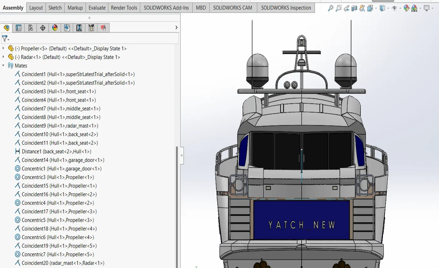
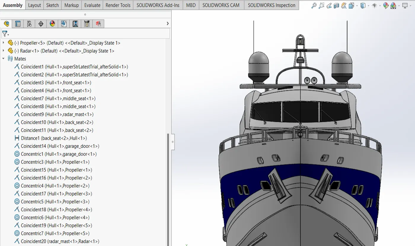
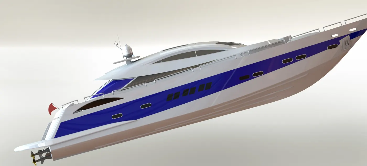
rendered models images:

Conclusion
the yatch assembly is created by importing all the parts in an assembly file. parts are created respecting the constrains given in the PDF references. rendering is done for assembly.
parts are provided appearances as specified in the learning material to enhance visual properties. photoView 360 is utilized for assembly renderings.
please find the link to the zip file models here: https://drive.google.com/file/d/1qFY0ac3_t96BTtj6Dd_tNGzmXwn_bR3o/view?usp=sharing