Radar Mast & Final Assembly of Yacht
1. Radar Mast
File (Google Drive): https://drive.google.com/file/d/1i-MJDLDo2Pq2b8uln9eQBknK5kLaCgFA/view?usp=share_link
Feature Manager Design Tree
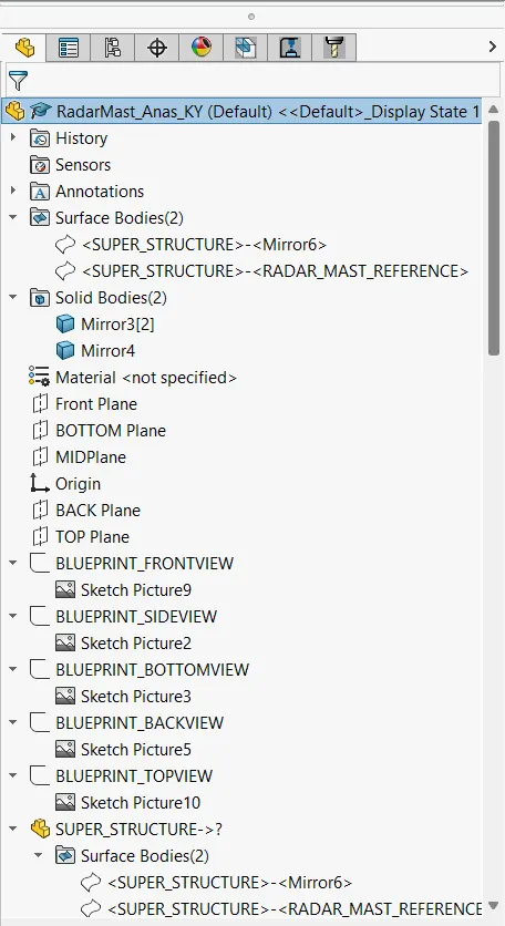
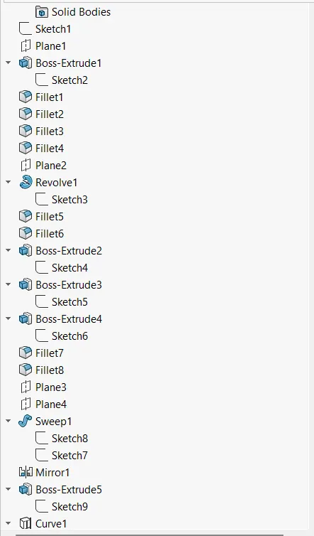
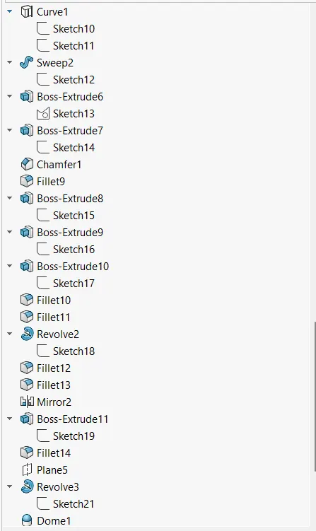
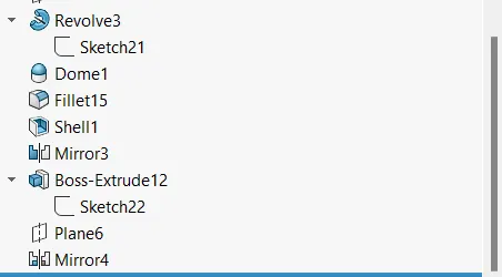
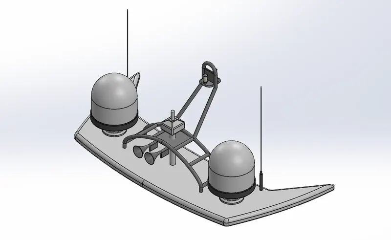
Isometric View
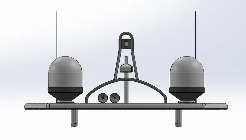
Front View
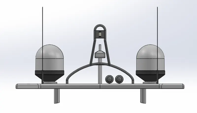
Back View
Top View
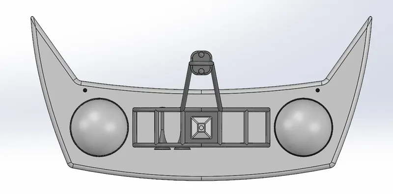
Bottom View
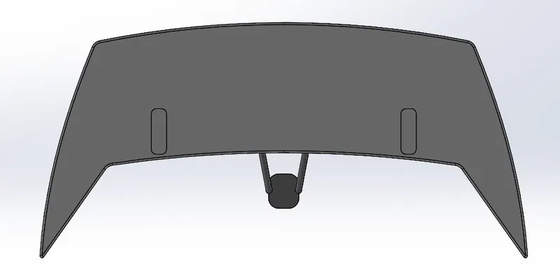
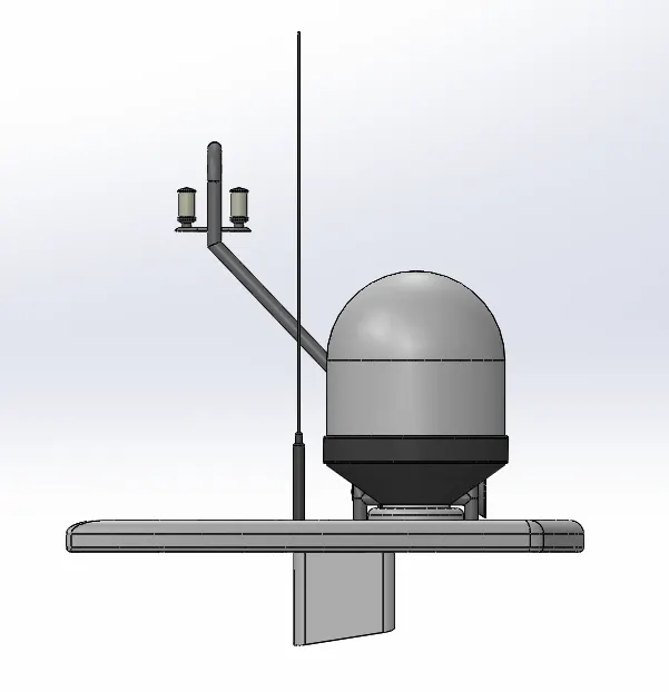
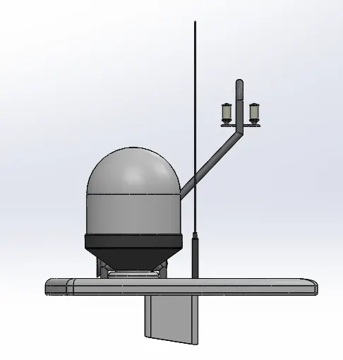
Left View Right View
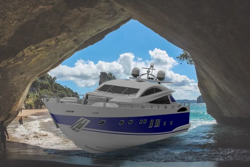
Design, Assembly, and Photo-Realistic Rendering of a Sunseeker Predator Yacht.
OBJECTIVE
The objective of this project is to use the Solidworks modeling software to design and model all the parts, using Solidworks tools, of a Sunseeker Predator Yacht and assemble it. Also creating a Photo-Realistic rendering of the yacht.
INTRODUCTION
In this project the Sunseeker Predator Yacht is taken as a conceptual model, to understand the 3D modeling methodology of Solid and Surface modeling. Every part of the yacht was designed and modeled using SOLIDWORKS. Then the modeled parts were assembled by adding proper mates and constraints to create the Model of the Yacht and then using Photo-Realistic rendering tools like Photoview 360 and Solidworks Visualization to create a realistic image of the Yacht and presentation of the model in Realistic environments.
The SOLIDWORKS is an industrial tool, for mechanical design automation applications, that lets designers quickly model their ideas, experiment with features and dimensions, produce 3D models and detailed drawings and also represent their ideas in photorealistic images.
Photo-View 360 is a SOLIDWORKS add-in that produces photo-realistic renderings of SOLIDWORKS models. The rendered image incorporates the appearances, lighting, scene, and decals included with the model.
SOLIDWORKS Visualize is a photo-realistic rendering tool that utilizes our CAD data to create the best quality images or animations.
DESIGN PROCESS
Defining the Problem
- We can’t find a solution until we have a clear idea of what the problem is.
Collecting Information
- Collect sketches, and photographs and gather data to start inspiring us.
Finding out connection
- Begin to sketch, and study data and information so we can find out how all the data and information we’ve collected may relate to each other.
Develop Solutions
- Relations between data and info give us a basic idea of solutions so now we can develop solutions using these relations, there may be more than one solution.
Best suited solution
- Every solution has its uniqueness, by realizing the factors affecting our project’s main goal, which factors are affecting its design like cost, quality, customer satisfaction, and more these factors should be considered and then choosing one of the best-suited designs will be easy.
Improve
- Reflect on all of our feedback and decide if or to what extent it should be incorporated. It is often helpful to take solutions back through the Design Process to refine and clarify them.
DESIGN REQUIREMENTS
The essential requirements of a good product design are listed as follows:
- Product must optimally perform its main function.
- It must be easy to repair at a low repair cost.
- It must be very reliable to use.
- It must follow principles of aesthetics.
- It must be a durable one.
- It can be easily produced in large numbers at minimum production cost.
- It must be simple to produce and use (handle).
- It must also be compact.
DESIGN INTENT
In this project, we will be able to sketch and build an entire Sunseeker Predator Yacht using SOLIDWORKS to understand the 3D- Modelling methodology of Surface Modelling.
In this project, we’ll learn, curve generation, surface creation from curves and sketches, and different types of surfaces - boundary surfaces - lofted surfaces - filled surfaces - ruled surfaces- reference planes - surface trims - surface knit - move/copy surfaces - mirror surfaces, etc.
The following are the key parts/models we will deal with in surface modeling using SOLIDWORKS.
- Blueprint set-up
- Modelling of propellers, radar
- Modelling of the hull, garage door
- Modelling of rear seats, middle seats, and front seats
- Creation of the superstructure
- Final assembly model of the Predator Yacht
Design Approach
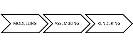
Design Methodology
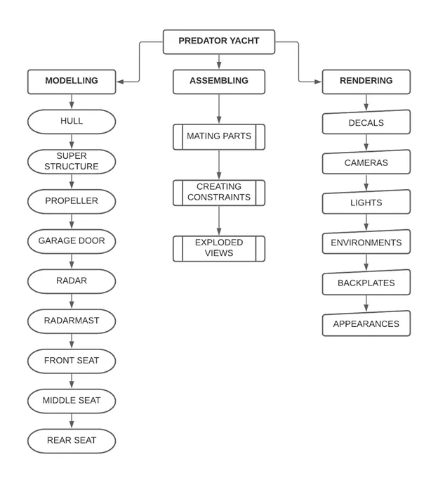
PART MODELLING DESCRIPTION
1. BLUEPRINT SETUP:
A blueprint is a reproduction of a technical drawing or engineering drawing using a contact print process on light-sensitive sheets. A blueprint is a guide for making something, it's a design or pattern that can be followed. They were easier to read and faster to make.
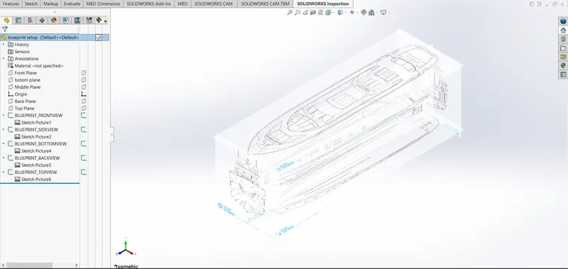
The above-shown Blueprint was used to model the Yacht with a fully defined constraint. For setting up the Blueprint the Sketch pictures options were used and placed the different blueprints at the required planes.
2. PROPELLER
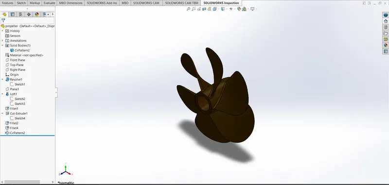
There can be one, two, or three propellers. It is the most important part of the ship without which a ship can't move. So, the main function of the propeller is to propel the ship in the forward direction by producing thrust on water. Its working principles are Newton's third law of motion and Bernoulli's theorem.
COMMANDS USED TO MODEL
In Sketch
- Spline
- Circle
- Line
In Features
- Revolved Boss/Base
- Lofted Boss/Base
- Extruded Cut
- Reference Plane
- Circular Pattern
- Fillet
MODELLING PROCEDURE
- The center portion of the Propeller was sketched and revolved using Revolved Boss/Base.
- Then the Blades were created using the Reference Plane, Lofted Boss/Base, and Fillet.
- Then the remaining five blades were created by using Circular Pattern.
- Then the center circular portion was removed using Extruded Cut option.
- Finally the part was saved by adding the proper appearance.
3. RADAR
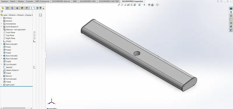
Marine radars are X-band or S-band radars on ships used to detect other ships and land obstacles, and o provide bearing and distance for collision avoidance and navigation at sea. They are electronic navigation instruments that use a rotating antenna to sweep a narrow beam of microwaves around the water surface surrounding the ship to the horizon, detecting targets by microwaves reflected from them, generating a picture of the ship's surroundings on a display screen.
COMMANDS USED TO MODEL
In Sketch
- Line
- Text
- Circle
- Point
In Features
- Extruded Boss/Base
- Extruded Cut
- Sketch Pattern
- Fillet
- Mirror
- Split Line
MODELLING PROCEDURE
- By drawing the required sketch the body of the Radar was created using Extruded Boss/Base.
- By using the Sketch Pattern the four Dotted holes were created using Extruded Boss/Base and Extruded Cut.
- The Radar has a circular slot underneath which was created using the Extruded Cut.
- The other half was mirrored with the help of mirror tool.
- The Text over the Radar was created using the Text option in sketch and then the Split Line was used to generate over the face of the radar.
- At last the radar must be filleted around the edges of the body and also around the four holes.
- Finally the part was saved by adding proper appearance.
4. HULL
A hull is the watertight body of a ship or boat. The hull may open at the top (such as a dinghy), or it may be fully or partially covered with a deck. ... The line where the hull meets the water surface is called the waterline.
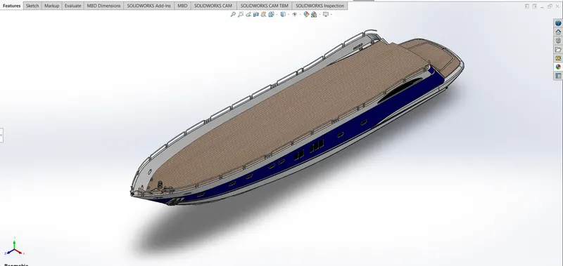
The hull of a ship is the most notable structural entity of the ship. To define the hull, it can be said that it is the watertight enclosure of the ship, which protects the cargo, machinery, and accommodation spaces of the ship from weather, flooding, and structural damage.
- The hull is a watertight body of a vessethatch that may be open or may be partially covered with a deck.
- Hull has several watertight decks and bulkheads as the major transverse membrane.
- The intermediate member of the hull consists of girders, we, bs, and stringers.
- Depending on the structural arrangements, there may be longitudinal members for strengthening purposes.
COMMANDS USED TO MODEL
In Sketch
- Line
- Spline
- Circle
- Rectangle
- Arc
- Slot
- 3-D Sketch
- Sketch picture
In Surfaces
- Extruded Surface
- Revolved Surface
- Lofted Surface
- Surface Trim
- Surface Fill
- Surface Knit
- Delete Face
In Features
- Project Curve
- Chamfer
- Fillets
- Reference Plane
- Split
- Split Line
- Extruded BossBase
- Extruded Cut
- Mirror
MODELLING PROCEDURE
- The first step for modeling the Yacht was creating a blueprint for it.
- Then the blueprint was placed at the required planes, by using it first the hull was designed.
- To get the shape of the hull the projected curve was produced by drawing the required sketch using splines with the help of a blueprint.
- Then the curves were lofted to create a lofted surface and the remaining unwanted surface was trimmed using surface trim.
- Then the back portion of the hull where the propeller needs to be placed was extruded using Extruded Surface and all the surfaces created must be Knitted together to remove the gaps between the surfaces.
- Then the offset option was used and another surface has created both surfaces were filled using surface fill to create the outer shell of the hull which will be converted into a solid body at last.
- Shell feature was used to create the front portion of the hull where the deck surface meets.
- Then the deck surface was created using Extruded Boss/Base and Extruded Cut.
- Then the required chamfers and fillets were created wherever necessary.
- All the windows and Portholes were created using Extruded Cut and Fillets were added around the edges.
- For creating the smooth edges around the berth window the reference plane was created and a circle for the required dimensions was make pierced and then swept around the edge of the windows.
- The Rails at the bottom of the yacht were created using Extruded Boss/Base and the chamfers have been applied on both sides.
- The Cable Rollers were created using Extruded Boss/Base and Swept Boss/Base and the head part of it was created using Revolved Boss/Base Extruded Cut was used to cut through the extrude and a Dome was created over it.
- Helix/Spiral sketch was created to sweep the rope around the Cable Rollers.
- By using the Slot option the Rope hangers were extruded and the dome was applied and then the Linear Pattern was used to create one more.
- The window bars were created using Extruded Boss/Base.
- The staircase was created by using extruded boss/base and the hand support bar was created using Swept Boss/Base.
- The Railings around the Hull were generated with the help of a blueprint and the projected curve was produced and the railing reference was swept using Swept Boss/Base.
- The Axles for the propeller and the surfer were created using Revolved Boss/Base option and using the 3d sketch.
- The Anchors were created by sketching the first half and extruding using Extruded Boss/Base and the other half was mirrored.
- Finally the Garage Portion was created by using Extruded Cut and the portion was saved for later use by using the Split option.
- By using the Split line option the Painting portion for our hull was split separately.
- Then the other half of the Hull and the Axle of the surfer and propeller were mirrored to form the complete hull using the Mirror tool.
- Now the part was saved by adding proper appearances and fillets.
5. GARAGE DOOR
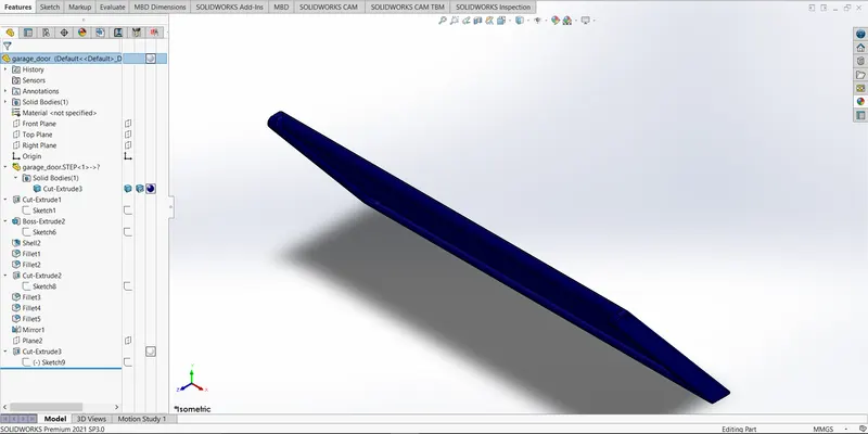
A garage door is a large door in a garage that opens either manually or by an electric motor (a garage door opener). Garage doors are frequently large enough to accommodate automobiles and other vehicles. The operating mechanism is spring-loaded or counterbalanced to offset the weight of the door and reduce the human or motor effort required to operate the door. Less commonly, some garage doors slide or swing horizontally. Doors are made of wood, metal, or fiberglass, and may be insulated to prevent heat loss.
COMMANDS USED TO MODEL
In Sketch
- Line
- Spline
- Circle
- Text
In Features
- Extruded Cut
- Reference Plane
- Fillet
- Shell
- Mirror
MODELLING PROCEDURE
- The solid body split while creating the Hull was imported to model the Garage Door.
- By using the Extruded Cut the Chamfered face for the door was created.
- Then by using the shell feature the solid body for our garage door was created and proper fillets were applied.
- Then the door holders on both sides were created using Extruded Cut.
- Then the second half of the Garage Door was created using the Mirror tool after applying the required fillets.
- Then the text over the garage door “MY YACTH” was created using the text option in the sketch feature.
- Finally the part was saved by applying proper appearance.
6. FRONT SEAT
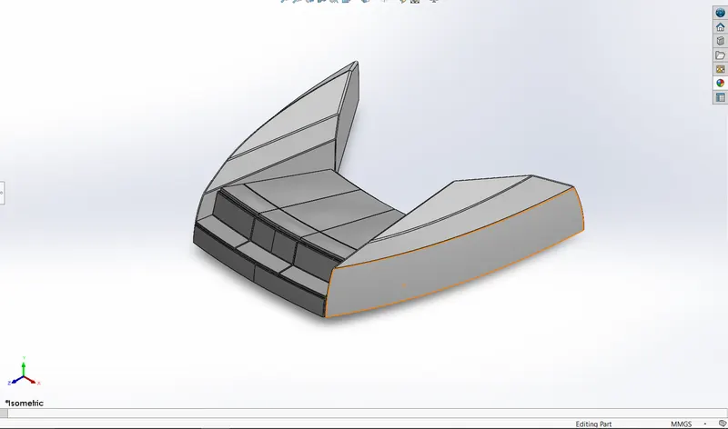
Front seats feature two connected seats that are built back-to-back from one and other. They have a built-in storage unit underneath them. Lounge seats can also fully recline right back to make it easier for you to kick your feet up and get more comfortable. The front seat in our model was placed before the superstructure and also it has sun pads to rest on it. Sun pads are a great way to reclaim lost space on our boat.
COMMANDS USED TO MODEL
In Sketch
- Sketch Picture
- Line
- Spline
- Circle
- Arcs
In Surfaces
- Extruded Surface
- Lofted Surface
- Trim Surface
- Filled Surface
- Knit Surface
- Swept Surface
- Revolved Surface
In Features
- Extruded Cut
- Revolved Boss/Base
- Chamfer
- Fillet
- Mirror
- Dome
MODELLING PROCEDURE
- The Front seat of the Yacht was also created with the help of Blueprint.
- The first half was modeled and the other half was mirrored using the Mirror tool.
- The front seat was placed before the Superstructure facing the Water Feature of the Superstructure and the back end must be placed on the bow of the Yacht.
- The body of the Front Seat was modeled using Swept Surface, Extruded Surface, Filled Surface, and Lofted surface, and the unwanted part was removed using Trim Surface.
- Then the four Rest Beds were created using Extruded Boss/Base and the dome was created over the face of the beds separately.
- Then the required fillets and chamfers were created with extruded thin surfaces.
- Finally the part was saved by adding proper appearances.
7. MIDDLE SEAT
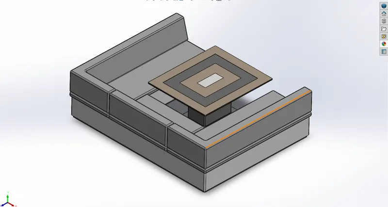
The middle seat in our model was placed just behind the superstructure. It is provided with a luxury table to dine out. It can also be used to have casual meetings with co-passengers.
COMMANDS USED TO MODEL
In Sketch
- Sketch Picture
- Line
- Rectangle
In Features
- Extruded Boss/Base
- Chamfer
- Fillet
- Mirror
- Reference Plane
MODELLING PROCEDURE
- The Middle Seat was created using the Extruded Boss/Base and by applying the Chamfers and fillets as required.
- All the surfaces created must be Knitted together by using the Knit Surface option.
- The Dining Table was also created using Reference Plane, Extruded Boss/base, Offset, Chamfers, and Mirror.
- Then the second half of the Middle Seat must be Mirrored symmetrically.
- Finally the part was saved by applying the proper appearances.
8. REAR SEAT
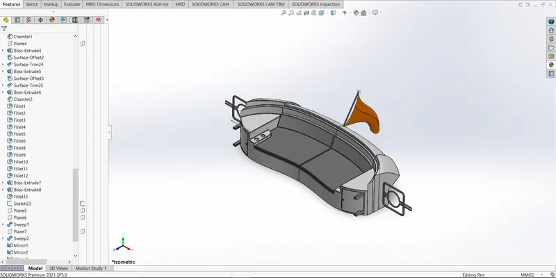
The rear seat was placed at the end of the deck surface. The rear seat consists of locker racks and steel doors for our stairs. The flag was also placed behind the rear seat since it’s the end part of our yacht. To have a nice view from the yacht while having a drink the rear seat was also provided with a slot to rest the glass or mug.
COMMANDS USED TO MODEL
In Sketch
- Sketch Picture
- Line
- Spline
- Circle
- Arcs
- Rectangle
In Surfaces
- Swept Surface
- Extruded Surface
- Off-set Surface
- Filled Surface
- Knit Surface
- Ruled Surface
- Lofted Surface
In Features
- Reference Plane
- Extruded Boss/Base
- Revolved Boss/Base
- Fillet
- Mirror
MODELLING PROCEDURE
- The main body of the Rear Seat was modeled using Swept Surface, and Off-set Surface and the remaining portion was trimmed using the Trim Surface tool.
- By using the Reference Plane the Seats were created with the help of a Lofted Surface, Surface Trim, and Extended Surface.
- The Flag Post was created using Revolved Boss/Base and the Flag was created by drawing the required 3D sketch and then the 3D sketches were lofted to form the Flag.
- The Tail Lamps were created by using Extruded Boss/Base, Fillets, and Mirror tools.
- The Steel Gates For Stairs were designed by using the reference plane and the Swept Surface.
- To remove the gaps all the Surfaces must be Knitted together using Knit Surface.
- The required fillets and chamfer were created before mirroring the second half using the Mirror tool and after mirroring the uncreated areas were filleted again.
- Finally the part was saved by adding appropriate appearances.
SUPERSTRUCTURE
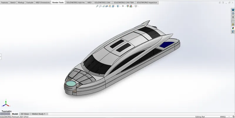
A superstructure is an upward extension of an existing structure above a baseline called ground level and it usually serves the purpose of the structure's intended use. A superstructure is a decked structure on the freeboard deck, extending from side to side of the ship.
COMMANDS USED TO MODEL
In Sketch
- Sketch Picture
- 3D Sketch
- Line
- Spline
- Circle
- Rectangle
- Center Point Arc
In Surfaces
- Extruded Surface
- Swept Surface
- Ruled Surface
- Knit Surface
- Trim Surface
- Extend Surface
- Filled Surface
- Lofted Surface
- Revolved Surface
- Fillet
- Chamfer
In Features
- Project Curve
- Reference Curve
- Convert Entities
- Split
- Split Line
MODELLING PROCEDURE
- The deck surface from the hull was imported and the superstructure was modeled over it.
- The side surface of the Superstructure was created by using Extruded Surface, Lofted Surface, Filled Surface, Trim Surface, and Knit Surface.
- The Front side of the Superstructure was designed to have four rest beds which were created using Extruded Boss/Base, Fillet,s, and Dome.
- The front edge of the superstructure was provided with a Water Feature which was created using Extruded Boss/Base, Extruded Cut, and filled with a water appearance.
- The Windshield was created by Extruded Cut and the wipers were created by using g 3D sketch and reference plane with the help of Swept Boss/Base.
- The Portholes for the Superstructure were created by using Extruded Surface, Trim Surface and Extend Surface.
- Ruled Surface was used to fill the teft-output edges.
- The Back Doors of the Superstructurwereas were created using Extruded Cut, Fillets and Reference Plane.
- Then all the surfaces generated were Knitted together to form a solid body.
- The Superstructure consists of two surface bodies and five solid bodies.
- One of the surfaces was the Deck Surface the other one was used to place the Radar Mast so it was renamed as Radar Mast reference Surface.
- Then the other half was mirrored and the proper fillets and appearance were added and finally the part was saved.
10. RADARMAST
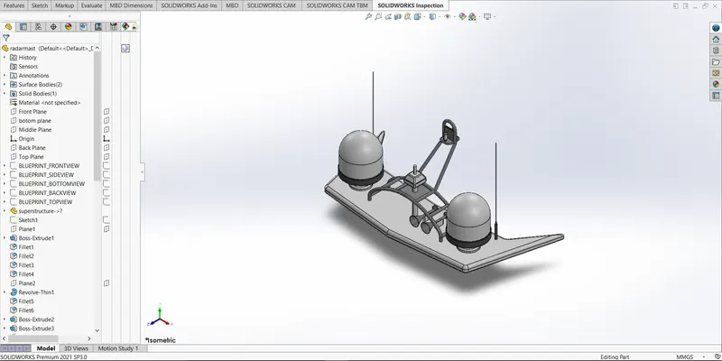
A mast is a vertical ship structure mounted on top of bridge and forward of the forecastle towards the ship’s bow. It accounts for the support platform for the ships derrick and hold necessary equipment’s such as radars, navigation light and ships horn in case of foremast. They are made of high tensile steel with added rigidity based on the size of derricks it holds. Other than that a ships main mast is also used to hoist ships flag.
Out of different parts of ship the main job of mast is to hold necessary equipment such as radar receiver, navigation lights, ships horn, flags and derricks in some case.
COMMANDS USED TO MODEL
In Sketch
- Sketch Picture
- Line
- Spline
- Rectangle
- Arcs
In Feature
- Extruded Boss/Base
- Lofted Boss/Base
- Revolved Boss/Base
- Swept Boss/Base
- Reference Plane
- Projected Curve
- Fillet
- Mirror
- Dome
- Shell
MODELLING PROCEDURE
- The first half of the Radar was Modelled with the help of blueprint and then the other half was mirrored with the help of Mirror tool.
- The body of the Radar was created using Extruded Boss/Base and Revolved Boss/Base.
- The antenna for the radar was also created using the Extruded Boss/Base.
- The lamp stand along with the connecting rod were created using the Swept Boss/Base and Mirror tool.
- The lamp was created by using the projected curve and then the curve was swept using swept boss/base.
- The horns were created using the Revolved Boss/Base, Dome and Shell.
- Then the fillets and chamfers were applied wherever necessary.
- Finally the part was saved by applying appropriate appearances.
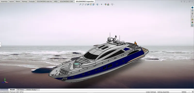
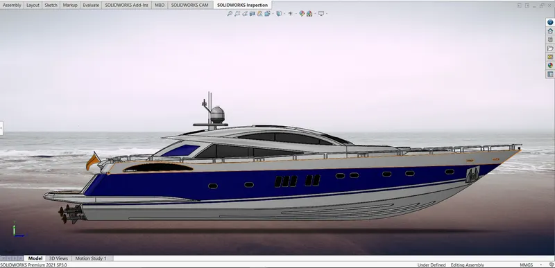
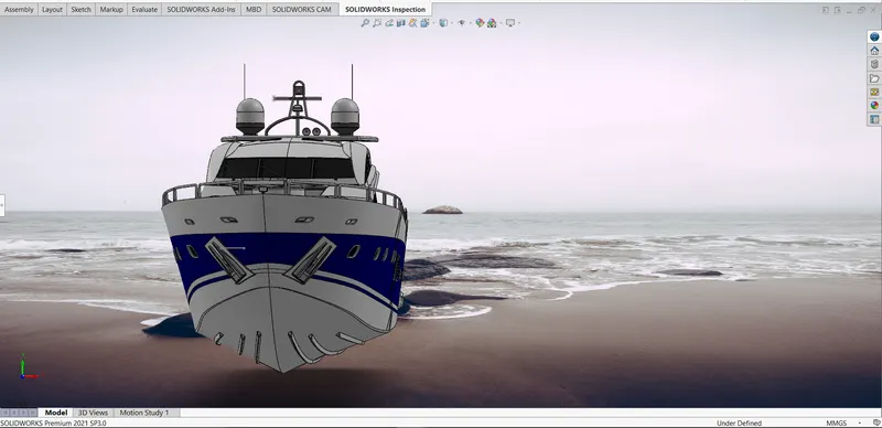
ASSEMBLY
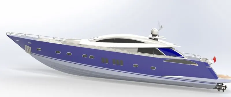
An assembly is a document in which parts, features, and other assemblies (sub-assemblies) are mated together. The parts and subassemblies exist in documents separate from the assembly. For example, in an assembly, a piston can be mated to other parts, such as a connecting rod or cylinder. This new assembly can then be used as a sub-assembly in an assembly of an engine. The extension for a SolidWorks assembly file name is SLDASM.
ASSEMBLY COMMANDS
- Smart Mate - A Smart mate is an assembly mating relation that is created automatically.
- Mate - A mate is a geometric relationship, such as coincident, perpendicular, tangent, and so on, between parts in an assembly.
- Mate group - A mate group is a collection of mates that are solved together. The order in which the mates appear within the mate group does not matter.
- Sub-Assembly - A sub-assembly is an assembly document that is part of a larger assembly. For example, the steering mechanism of a car is a subassembly of the car.
- Insert Components - We can insertmultiple instances of the group of components without closing the Property Manager.
Assembly Procedure
- Import all the parts manually by using Insert Components option.
- Then fix the Hull part by applying the coincident mate to the Top, Right and Front planes of the Assembly and Hull respectively.
- Then for each part apply the necessary mates required by the Blueprint using Coincident mates, Angle Mates, Distance mates etc.
- Advanced mate was also used wherever required.
ORTHOGRAPHIC VIEW
RENDERING
Rendering of the Solidworks model is done using PhotoView 360 and Solidworks Visualize.
PhotoView 360 is a visualization and rendering solution included with SOLIDWORKS. Providing a highly interactive environment for viewing designs as well as for creating photo-realistic renderings it can be used to showcase our designs.
SOLIDWORKS Visualize (formerly known as Bunkspeed) provides a suite of standalone software tools that combine industry-leading rendering capabilities with visual design-oriented features and workflows, allowing easy and fast creation of visual content that communicates a design's vision, passion, and emotion.
PhotoView 360
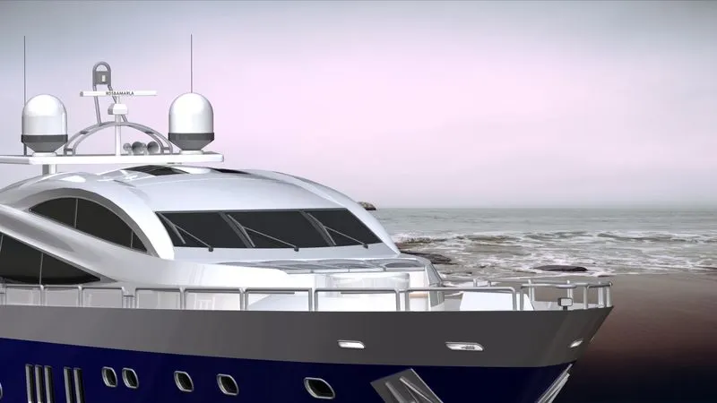
PhotoView 360 is a software package, separate to Solidworks, which generates digital lifelike images (photorealistic images) from SolidWorks files. PhotoView 360 is an easy and quick way to produce high quality photorealistic images.
- Environments - Environments can be looked upon as backdrops and can be applied in a similar manner as the appearances are applied to faces or parts
- Appearances - There are a wider range of appearances in PhotoView 360 than in SolidWorks. If we wish to change an appearance just drag and drop the chosen appearance onto the part and it will replace the existing one.
- Lighting - Lights may be added in the same way a photographer adds lights when taking photographs. PhotoView 360 uses the same lights as SolidWorks but also uses lighting from the rendering environment or scene. PhotoView 360 has the sophistication to trace light rays and reflections.
- Scenes - Each SolidWorks model is associated with a PhotoView 360 scene, for which you can specify properties such as environments and backgrounds. Scenes help to put products in context.
- Decals - Images, such as company logos, can be applied to models.
- Output - The rendered output from PhotoView 360 can be viewed on the screen, or saved to a graphics file.
- Options - PhotoView 360 has its own options. Options allow you to customize the PhotoView 360 settings to reflect your preferences. Options are divided into Output Image Settings, Render Quality, Bloom, Contour Rendering and Direct Caustics.
SOLIDWORKS Visualize
Quickly and easily create professional, photo-quality images, animations, and other interactive 3D content to get your products to market faster.
SOLIDWORKS Visualize allows us to leverage our 3D CAD data to create photo-quality content in the fastest and easiest way we can–from images to animations, interactive web content, and immersive Virtual Reality. It brings our products to life. SOLIDWORKS Visualize is the “camera” for our CAD data.
Some renderers are fast but output low-quality images. Some produce great quality but take six months to learn. Others are easy to use, but take four hours to render an image. SOLIDWORKS Visualize provides the right combination of quality, speed, and ease of use, and is the best renderer.
SOLIDWORKS VISUALIZE PROFESSIONAL
With SOLIDWORKS Visualize Professional we can tell a deeper 3D story about our product using our CAD data. It enables us to easily generate photo-quality stills and interactive animations to effectively communicate the most complex design details.
The features of SOLIDWORKS Visualize Professional are listed below,
- Demonstrate products more effectively with full animation of parts, models, appearances, cameras, and environments
- Import our SOLIDWORKS CAD Motion Studies for truly photographic animations
- Quickly show off the final design with one-click 360-degree spins
- Create interactive web content such as Interior Panoramas and Exterior VRs
- Present and compare varying design solutions side-by-side with multiple viewports and included Configurator tool
- Unleash our creative side with customizable Camera Filters
SOLIDWORKS Visualize Professional also includes key features to help increase productivity. The integrated Render Queue allows us to stack up jobs on our machine or a dedicated render farm to automatically complete one after the other, providing remarkable time savings.
Full Animation Suite (parts, models, appearances, cameras & environments)
- Simple one-click 360 degree turntable animations make this type of output a breeze to create.
- Part/Group/Model animations for animated exploded views, sequence animation, and more to explain complex mechanical movements and detailed designs.
- Camera animations with unique Animation Ribbon, which is an intuitive 3D representation of how the camera moves through the scene, making camera flys a snap to create.
- Sun Study output type allows Visualize users to see what the play of light looks like across their model throughout an entire day. This is perfect for interior designers who need to see how sunlight casts shadows from their interior concept throughout a complete day sun-cycle.
Custom camera Post-Processing (camera filters)
Unleash our creativity and add additional effects to your Visualize content with customizable camera filters and the new Bloom Filter, perfect for glowing LEDs, lights and sun highlights.
Render Queue
Similar to a printer queue, stack up render jobs to send all at once, for example at the end of the day, to remain productive during work hours and allow all the renders to cook overnight. The integrated Render Queue instantly boosts productivity allowing us to never wait for a render to finish again.
Procedure for creating visualization
With its simple, intuitive user interface, SOLIDWORKS Visualize requires virtually no learning curve and lets users produce content quickly. Even non-technical staff can start creating amazing content instantly.
- Create new project by importing the required assembly or models into the Solidworks Visualize
- Add the required appearance, environments, backplates and lights
- By using the camera tool position the designed model in a realistic view
- Make sure that the model touches the floor. It can be achieved by using snap to the floor option on Models
- By applying the required settings the required outputs can be rendered using output tool.
CONCLUSION
Thus the project Design, Assembly and Photo-Realistic Rendering of an American Predator Yacht was Modelled and Rendered successfully.