Radar Mast & Final Assembly of Yacht
Model Radar mast and Assemble the Yacht using SolidWorks
Solution:
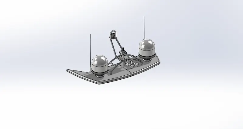
1.Radar mast
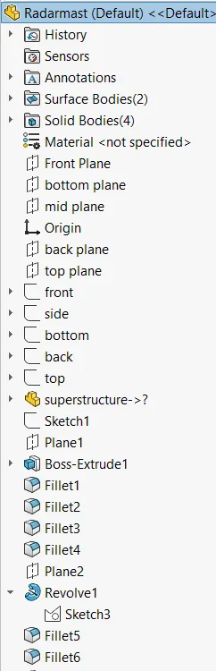
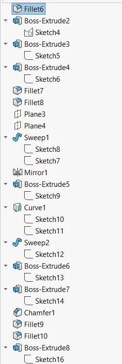
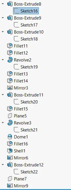
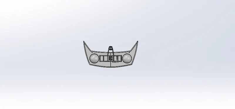
views:
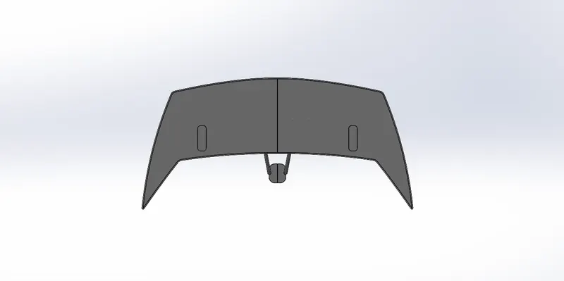
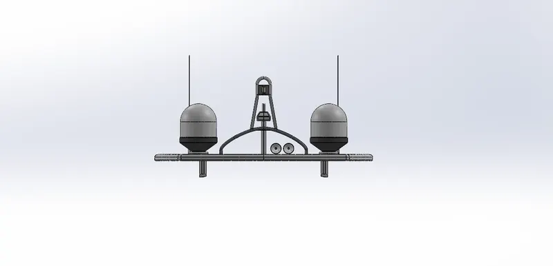
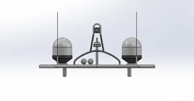
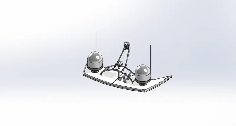
2.Assemble the Yacht Using Solidworks
OBJECTIVE
- To create parts of YACHT using Solidworks.
- To Assemble all the parts of YACHT.
- To know the application of decals,lights and camera etc.
- To create photorealistic model and rendering photoview 360 and solidwork visualize.
INTRODUCTION
SolidWorks is a solid modeling computer-aided design (CAD) and computer-aided engineering (CAE) application published by Dassault Systèmes. It has other ADD-in features like photoview360 which helps in rendering modelS to make it look photo realistic. In this project we learnt about detailed design of Americal chopper parts and assemblig them and rendering the final after assembly.
DESIGN METHODOLOGY
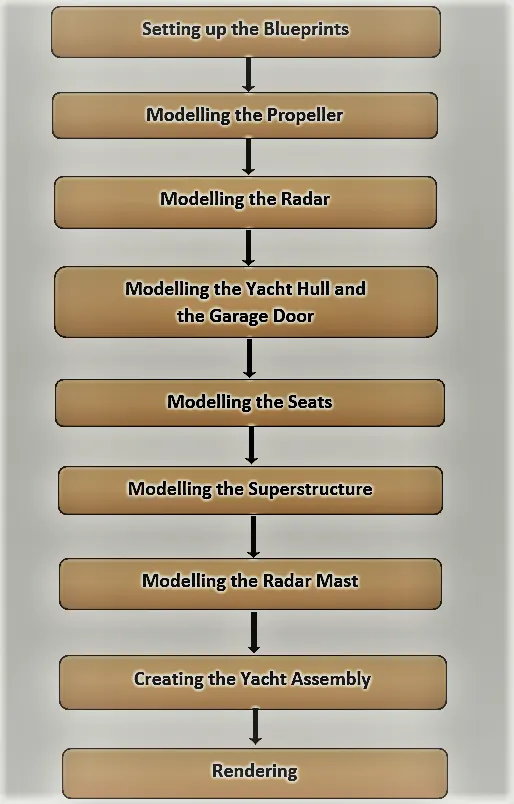
SOLIDWORKS TOOLS AND FEATURES USED TO MODEL YACHT
Fixing SKETCH for start any modeling:
2D TOOLS include in sketch are
- Line
- Circle
- Arc
- Spline
- Rectangle
- Circular Pattern
- Polygon
- Offset
- Fillet
- Mirror
- Ellipse
- Chamfer
- etc
(Each tool have their own unique uses also have contained more options)
Then using FEATURES we can change 2D sketch to any required 3D model objects and any desired item
- Blocks: We can save, edit and insert blocks from the drawing items and sketch entities that you use often such as standard notes, title blocks, label positions and so on you can attach blocks to geometry or to drawing views.
- Boss Extrude: Feature used for expand the object in 3D according to sketch plane.
- Revolve boss base: Feature is used to make cylindrical or circular 3D extrude along with a given reference axis as per drawn sketch.
- Extrude Cut: Extrude cut feature used to cut/remove the 3d object in linear path according to sketch.
- Revolve cut: Revolve cut is used to cut or reduce the extrude of cylindrical round surface.
- Lofted Boss/Base: Lofted boss is a feature used to achieve Complex Shapes. It does this by interpolating surfaces between various cross-sections of a model. These cross-sections can be sketches, faces, or edges.
- Sweep: This feature is used to sweep any kind of fully defined sketch along with the path.
- Sweep cut: Sweep cut is same as sweep feature but its directly proportional to sweep which makes a cut along with the sweep path.
- Linear Pattern: The linear parent is used to create a different number of instances required to create the pattern linearly.
- Circular pattern: Circular pattern is a feature used to make 3d feature into circular pattern according to number of insistences.
- Swept Surface: It is used to make a surface along with a path the curve is driven.
- Boundary Surface: Boundary surface is used to make a surface in between two finished surfaces.
- Curve Driven Pattern: Curve driven pattern is used to make any pattern which followed by the curve is sketched before.
- Curve Driven Pattern: Curve driven pattern is used to make any pattern which followed by the curve is sketched before.
- Loft Surface: Loft surface is used to make loft in between two profiles along with guide path.
- Knit surface: Knit surface is used to knit the two free edges or open edges of the surfaces together also it reduces the gap between the two edges of the surface.
- Move/copy body: This feature is used to move/copy the 3D body to one place to another place.
- Surface Trim: Primarily used to cut away material from a surface, and provides two modes: Standard and Mutual.
- Mirror: Mirror is used to mirror a feature or body by reference of the selected plane.
- Fillet: Fillet is a feature used for making round internal or external edges to avoid sharp edges and make it smooth.
- Chamfer: Chamfer is used to make a sharp edge or corner slightly tapered rather than being a perfect square.
- Split: Split tool is used to split single solid part into two solid parts. It is used to project an entity onto other surfaces or curved/planar faces.
- Dome: Dome is a feature used to make dome shaped extrude including elliptical dome.
- Shell: Shell feature is used to make to hollow space in solid part by selecting outer wall of the solid part and so removes the inner parts. It is also used to reduce the specific thickness.
- Combine: Combine tool is used to make integration of two solid parts which intersect each other as same solid part.
- Projection Curve: Projection curve is a 3D curve which is projected on the basis of the two different 2D curves in two different planes.
- Trim entities: it is used to trim the unwanted lines or extended entities in the sketch.
- Appearances: An appearance defines visual properties of the model including colour and texture. Appearances do not affect physical properties which are defined by materials. every material is a assigned a default appearance.
Blueprint:
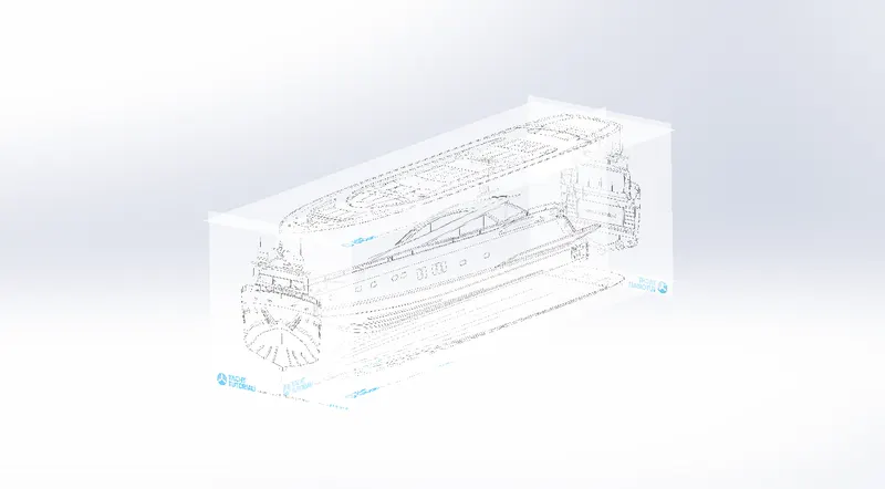
- All the blueprints were imported into a SolidWorks part file using the path : Tools - Sketch Tools - Sketch ,Picture and positioning it
- This Blueprint setup is then used to model all the parts
1.Propeller:
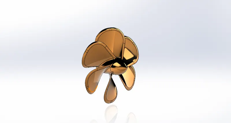
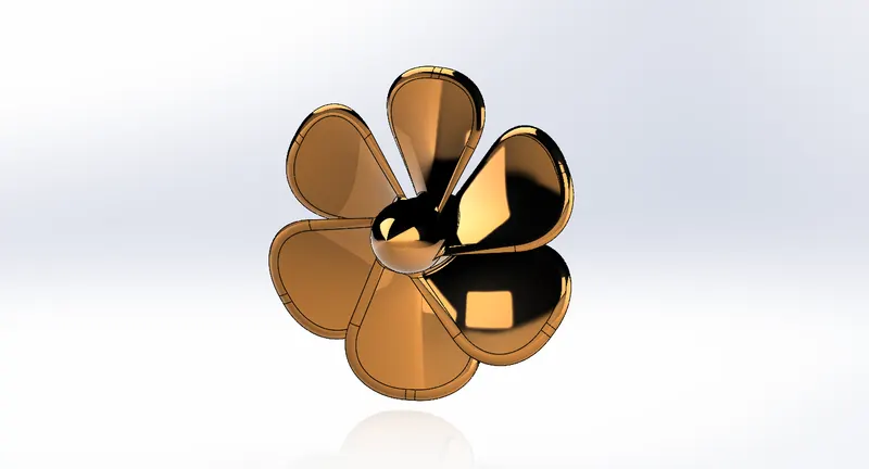
- A Propeller is a device with a rotating hub and radiating blades that are set at a pitch to form a helical spiral, that, when rotated, performs an action which is similar to Archimedes' screw.
It transforms rotational power into linear thrust by acting upon a working fluid, such as water or air. - The propeller is modelled simply by using solid modelling features suh as - Revolved Boss/Base, Extruded Cut, etc.
- Initially, a single blade is modelled using the Lofted Boss/Base feature.
It is then using in the Ciruclar Pattern feature to model the rest of the blades. - Fillets are added to remove off the sharp edges, provide appropriate curvature to the periphery of the blades and improve the outlook of the propeller.
2.Radar :
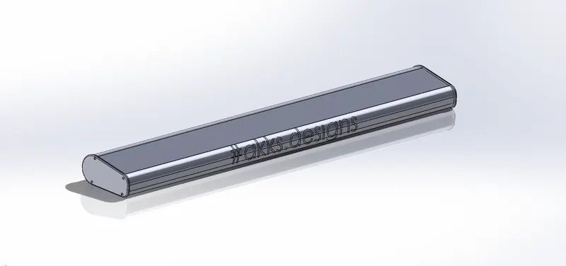
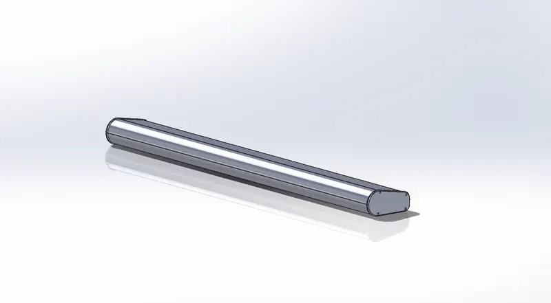

- Marine Radars are used to detect other ships and land obstacles, to provide bearing and distance for collision avoidance and navigation at sea.
They are electronic navigation instruments that use a rotating antenna to sweep a narrow beam of microwaves around the water surface surrounding the ship to the horizon, detecting targets by microwaves reflected from them, generating a picture of the ship's surroundings on a display screen. - The Radar is modelled very easily using the following features - Extruded Boss/Base, Cut Exrtude, Fillets, etc.
- Since, the radar is symmetric in shape, only haf the portion is modelled.
The other half is simply mirrored using the Mirror feature. The Merge Solids option is used to make one solid part. - Then Text is added
The text feature can be found at the mentioned path :
Tools - Sketch Entities - Text.
This text is then projected on the radar surface using the Split Line command.
3.Hull :
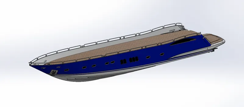
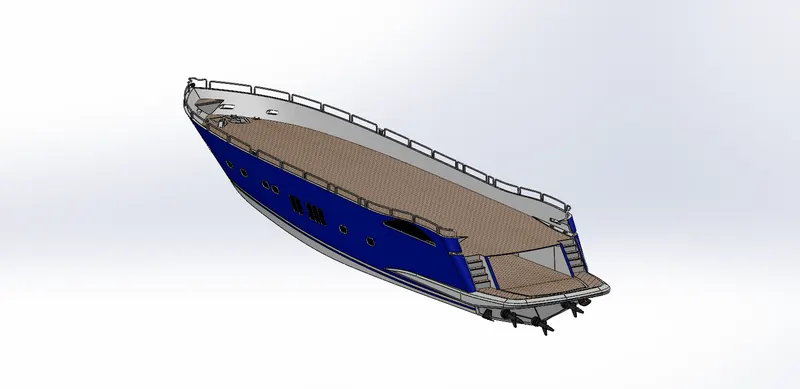
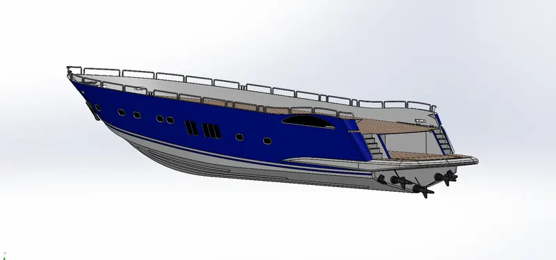
- A Hull is the watertight body of a ship or boat. The hull may open at the top (such as a dinghy), or it may be fully or partially covered with a deck.
Atop the deck may be a deckhouse and other superstructures, such as a funnel, derrick, or mast. The line where the hull meets the water surface is called the waterline.
METHODOLOGY:
- Here, the hull is essentially modelled by Surface Modelling.
The outer surfaces of the Hull are created using the features in the Surfaces tab. - For this, the Project Curve feature along with the different sketch tools, is used to create the outer peripheries of the surfaces.
Then, the surfaces are created using these curves and by using features such as Lofted Surface, Boundary Surface, Extruded Surface, Trim Surface, etc. - The Port Holes are modelled by using the Swept Boss/Base features after using Extruded Cut.
- The railing is modelled by creating projected curves through different sketch tools and then by using the Swept Boss/Base command with the curves as the sweep path.
- Fillet is used at all the required places where sharp edges are to be avoided. Also, providing fillets around the windows gives a good aesthetic appeal to the model.
- The Anchor is modelled directly as a solid i.e by using the features such as - Extruded Boss/Base, Extruded Cut, etc.
- These two symmetric parts are then carefully knitted together using the feature Knit Surface.
The Create Solid option is enabled to fill the inside portion of the Hull.
While doing so, it is ensured that the knitting is done properly. This can be done by carefully looking at each and every edge. A perfectly knitted edge looks black in colour, while a blue edge means that there is no association between the two faces altogether. - To give a more realistic outlook, decals are added on the deck surface as well as the stair surfaces.
Since, the Hull is symmetric, only half the portion is modelled, the rest half is mirrored using the Mirror feature. - Appearances is changed by providing colours at all the required faces. This gives the model a perfect and realistic look.
4.Gara ge door :
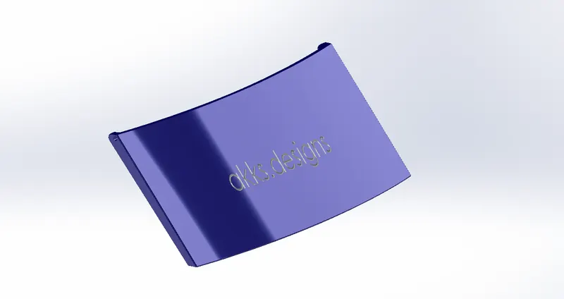
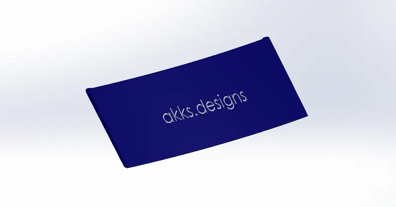
- Now, the Garage door is simply modelled using the garage portion which was carved out of the Hull.
- The unnecessary portion is removed off by using the Extruded Cut feature.
Fillets were provided to blend the sharp edges.
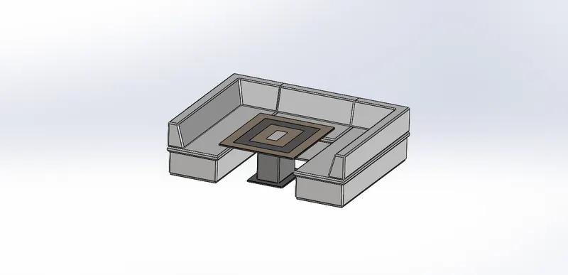
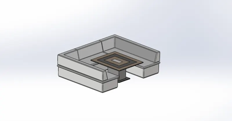
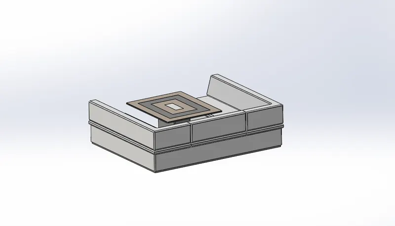
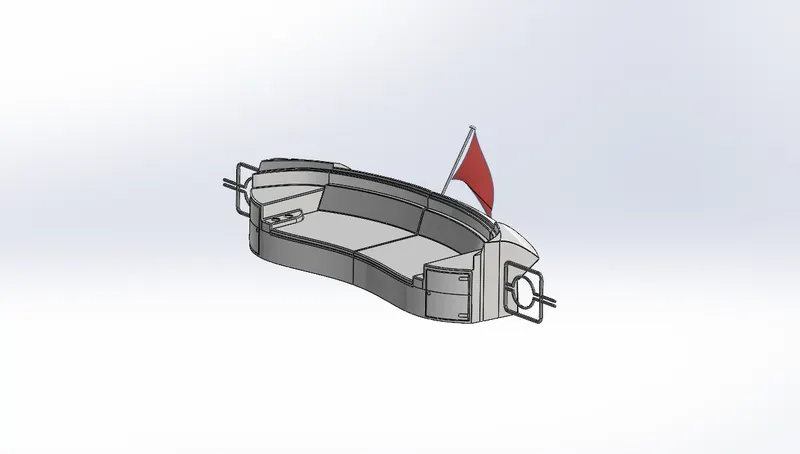
5. Seats:
Middle Seat:
Rear Seat:
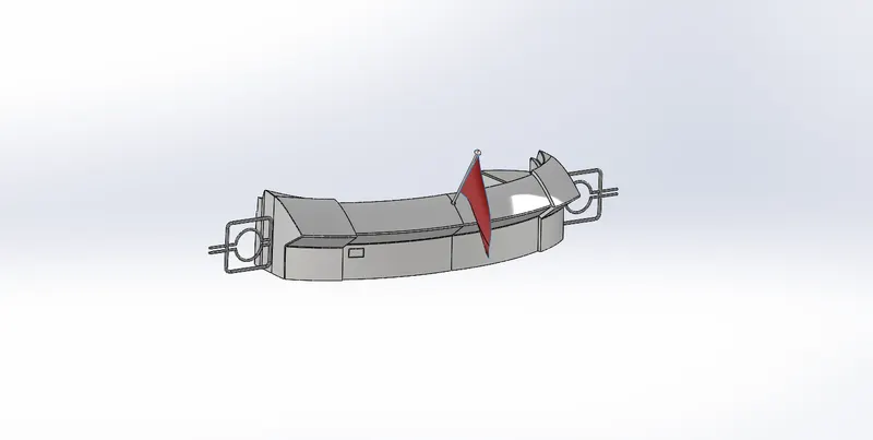
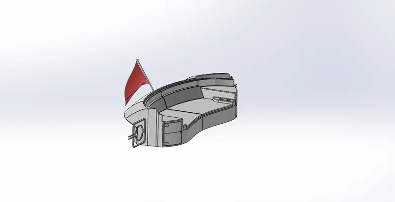
Front Seat:
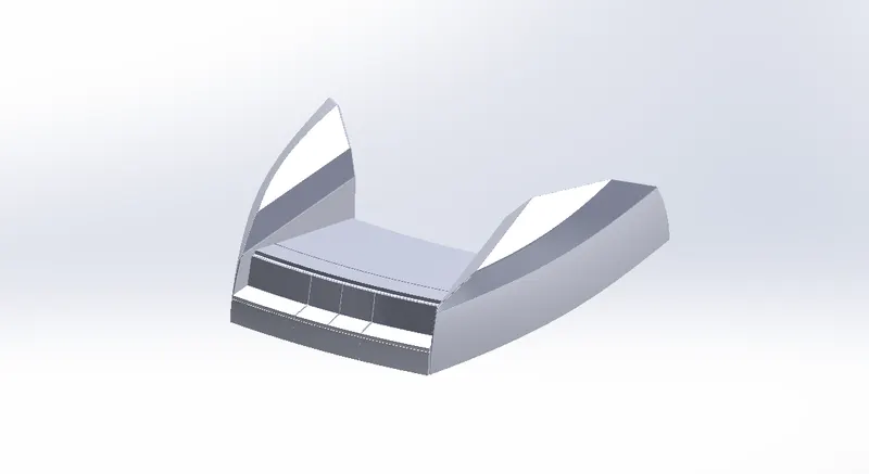
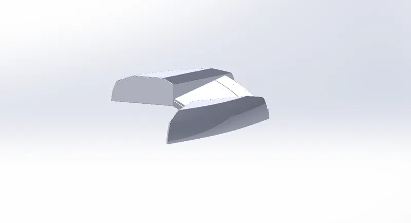
- Seats are modelled either by solid features or by using surface features.
- There are three seatings in the model - Front, Middle and Rear.
SEAT METHODOLOGY:
- Here, the Front and the Rear seats are modelled by first creating the outer surfaces using the features of the Surface tab. Then by creating a solid after carefully knitting the surfaces together using the Knit Surface feature.
6. Superstructure :
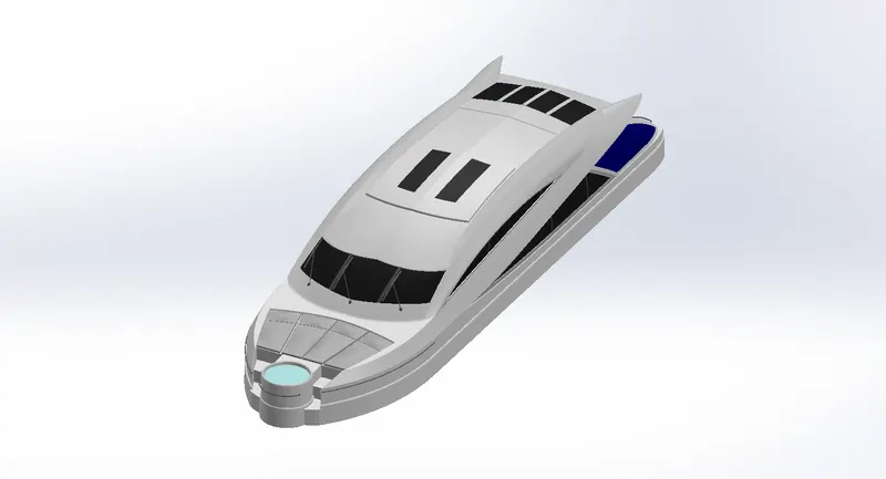
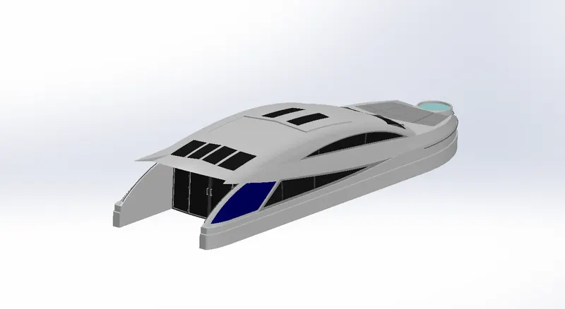
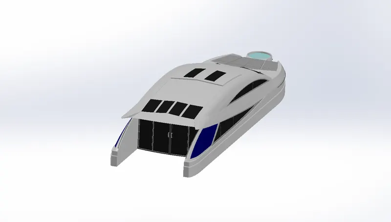
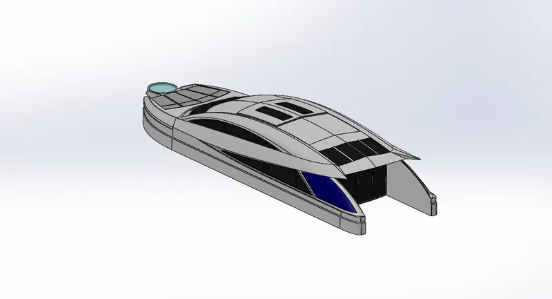
- On water craft, the superstructure consists of the parts of the ship or a boat, including sailboats, fishing boats, passenger ships, and submarines, that project above her main deck.
This does not usually include its masts or any armament turrets. - Here, the Superstructure is also modelled by creating the outer surfaces first, just as we did in the case of Hull.
SUPERSTRUCTURE METHODOLOGY:
- These surfaces are then mirrored using the Mirror command and then knitted together properly with the Knit Surface.
- Here as well, the railings are modlled by using the Swept Boss/Base feature.
- The Jacuzzi is just a cutout with a surface at the top to represent the water-level.
The surface is given a transparent appearance for this purpose. - The window edges are blended using the Fillet feature to give a smooth appearance.
- The vipers are modelled uisng solid features such as Extruded Boss/Base, Extruded Cut, Swept Boss/Base, etc. along with appropriate Chamfers and Fillets.
7. Radar Mast :
- The Mast of a sailing vessel is a tall spar, or arrangement of spars, erected more or less vertically on the centre-line of a ship or boat.
Its purposes include carrying sails, spars, and derricks, and giving necessary height to a navigation light, look-out position, signal yard, control position, radio aerial or signal lamp.
Large ships have several masts, with the size and configuration depending on the style of ship. Here, the mast consists of 2 light bulbs alongisde 2 antennas.
RADAR MAST METHODOLOGY:
- This mast is easily modelled using the solid features such as Extruded Boss/Base, Revolved Boss/Base, Swept Boss/Base, etc.
- The horns are modelled by using the Shell feature. This feature essentially removes off the inside material out of a solid 3D part, thereby making it hollow.
- The Mirror feature is used to mirror symmetric entities.
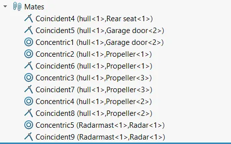
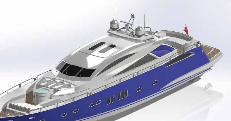
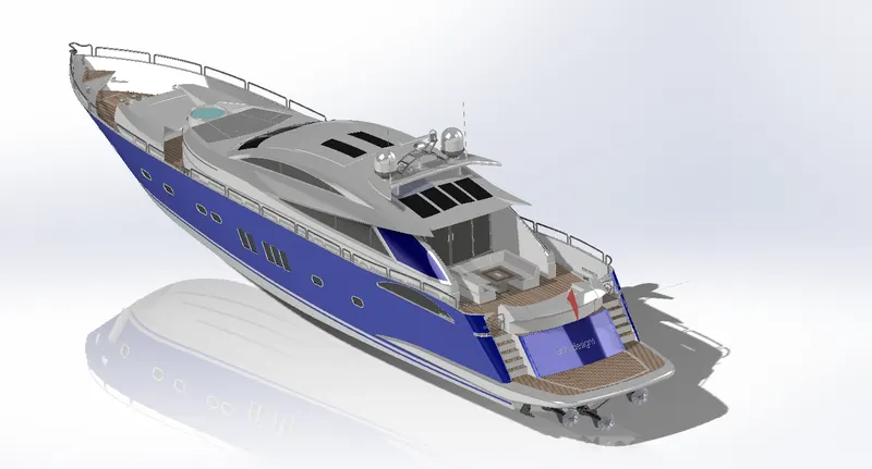
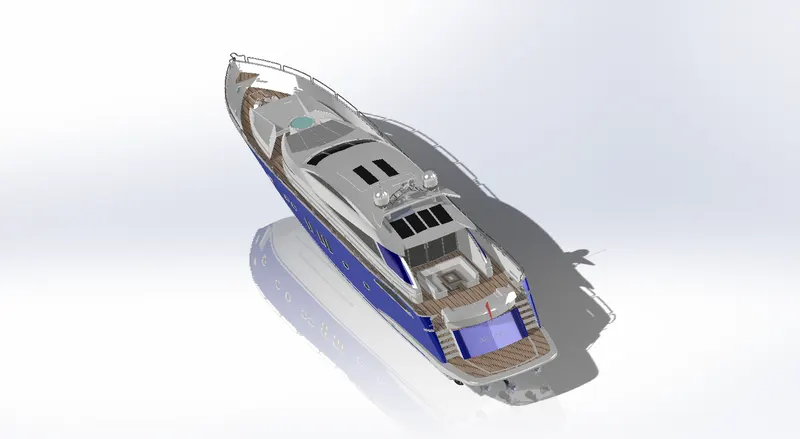
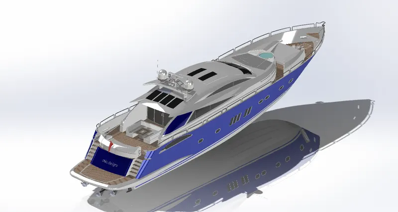
Creating the Assembly :
views:
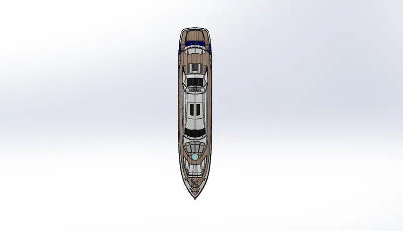
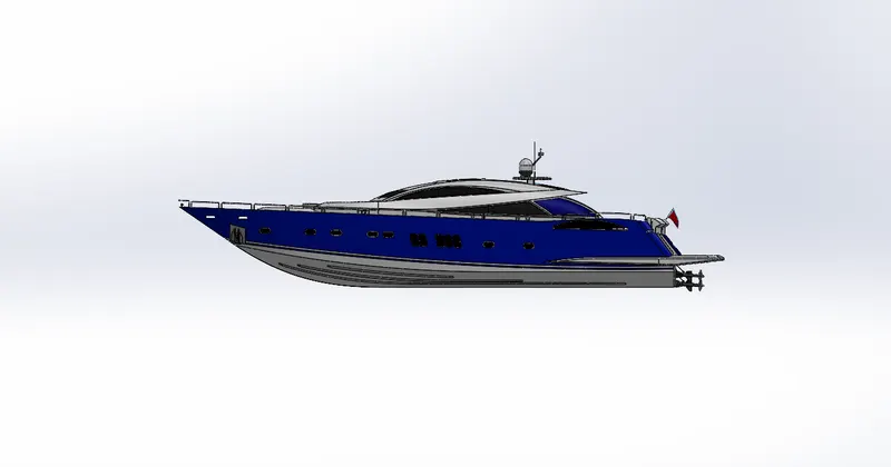
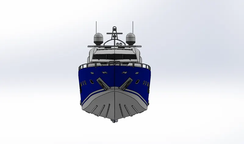
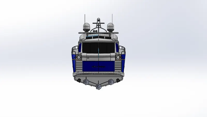
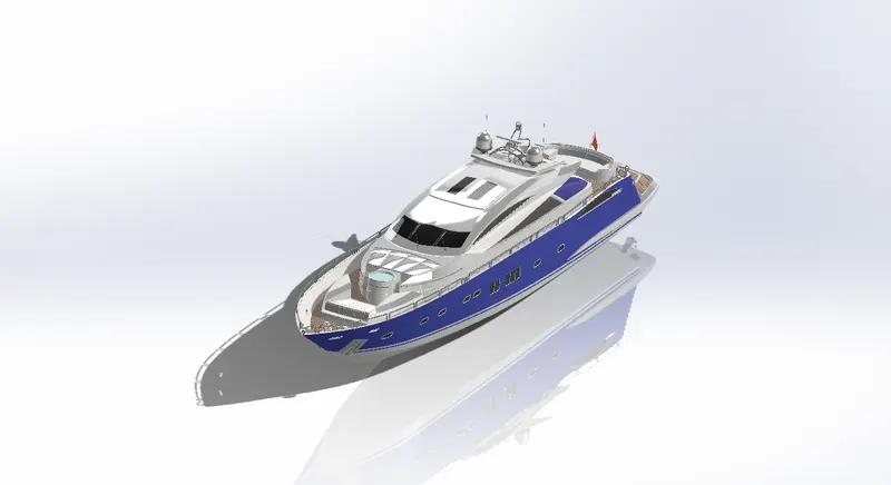
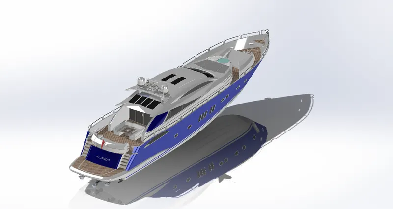
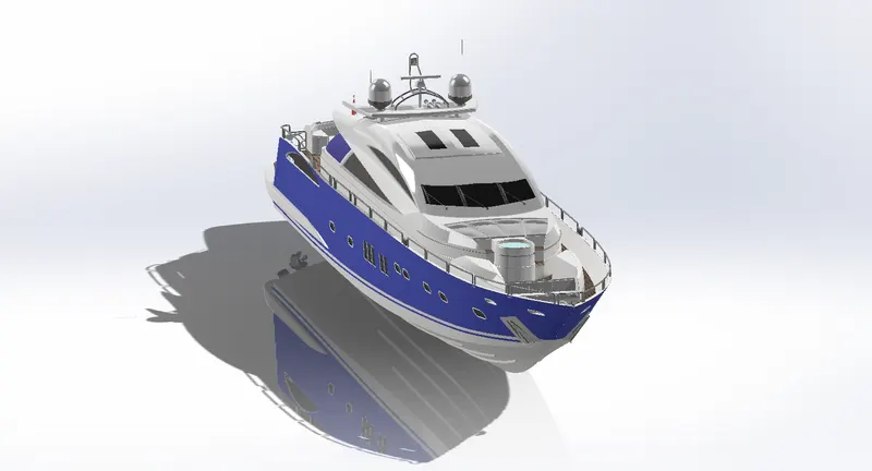
- All these individual parts are then assembled together using the SolidWorks Assembly file.
ASSEMBLY METHODOLOGY:
- First off, the Hull is fixed at the proper location.
Rest all the parts are then located with respect to this fixed Hull. -
Assembly:
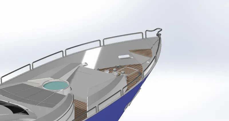
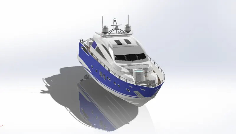
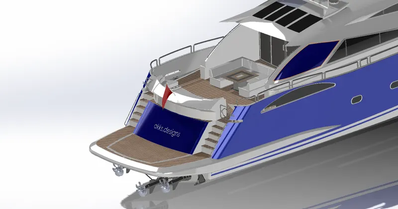
Rendering :
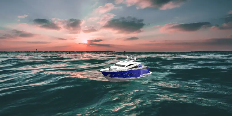
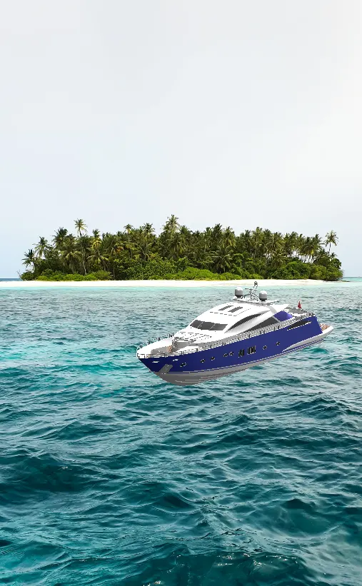
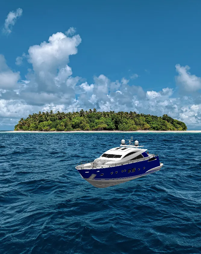
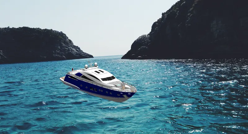
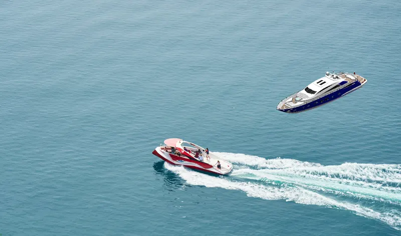
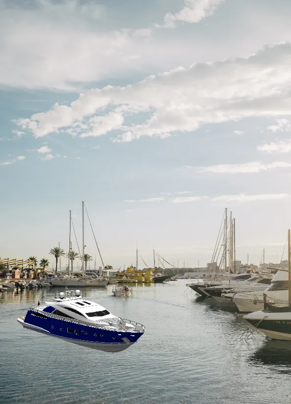
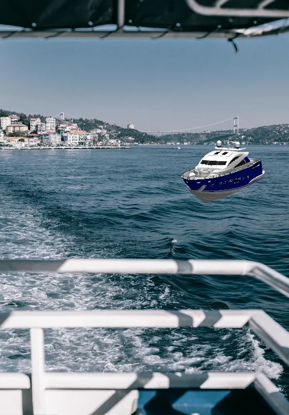
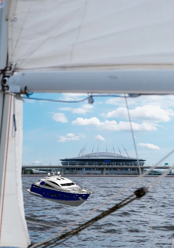
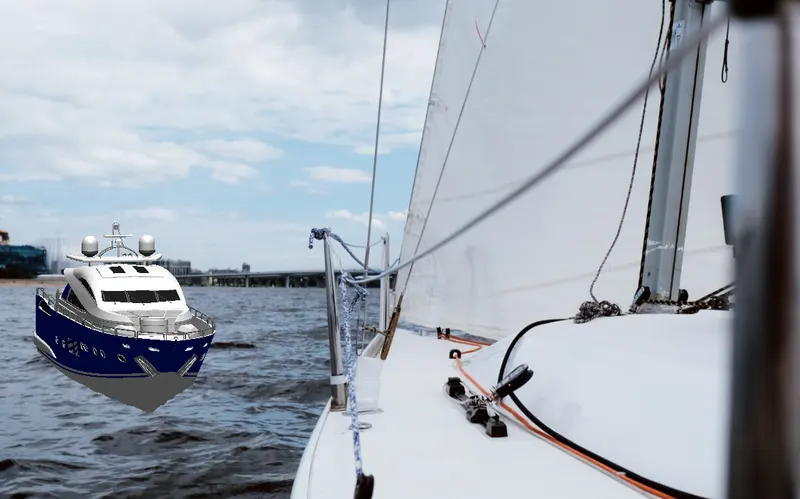
- Available Decals are added to enhance the outlook of few of the parts.
- The Yacht Assembly is rendered using the Add-In SolidWorks Visualize tool provided by SolidWorks.
- Proper Scene is created for the rendering.
Appropriate Environment is set up for this purpose. Also, a suitable Backplate is chosen out of the library.
Camera is set up by providing appropriate location. - The Perspective view is enabled to ensure real-time look.
- Now, after providing suitable appearances the model is rendered
CONCLUSION :
- The parts are sketched and modelled in the SOLDWORKS.
- The modeled parts are assembled with possible mates in to the main assembly of Yacht
- The decals are applied to faces of parts.
- The realistic image was rendered with the use of the Solidworks visualize.
REFERENCE
- skill-lync.com/student-projects
- help.solidworks.com
- www.techtarget.com