Boeing-747 _ Final_Project of Boeing
Boeing-747 _ Final_Project of Boeing
OBJECTIVE:
- To set up the blueprints for Boeing 747-8.
- To model the individual parts of the Boeing 747-8 using SolidWorks.
- To assemble all the parts with proper mates.
- To give proper appearances and decals for the parts.
- To position the assembly and set up cameras, lights and environments.
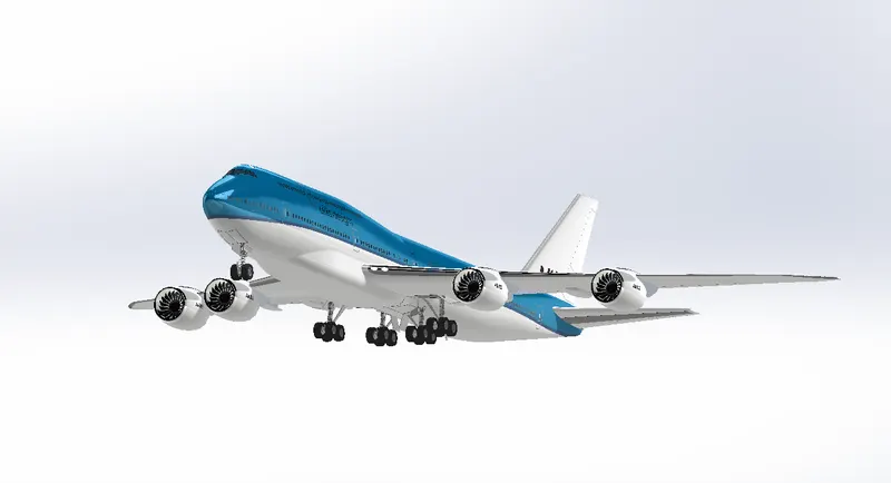
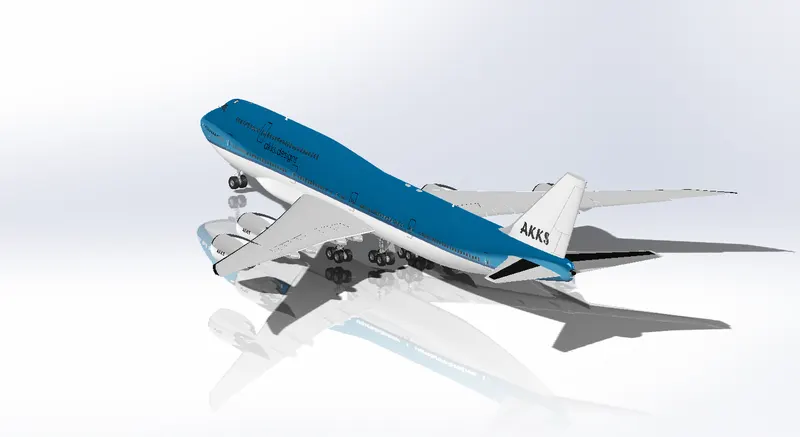
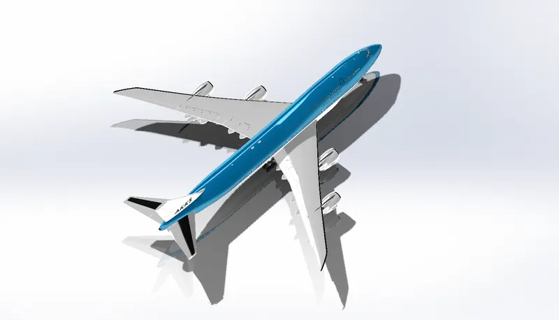
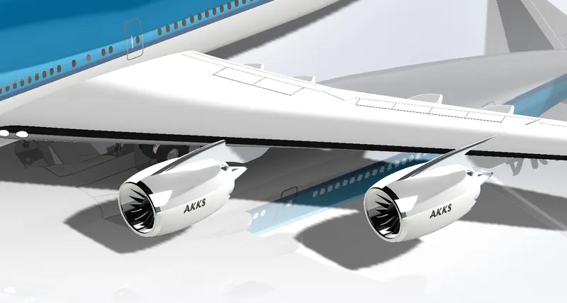
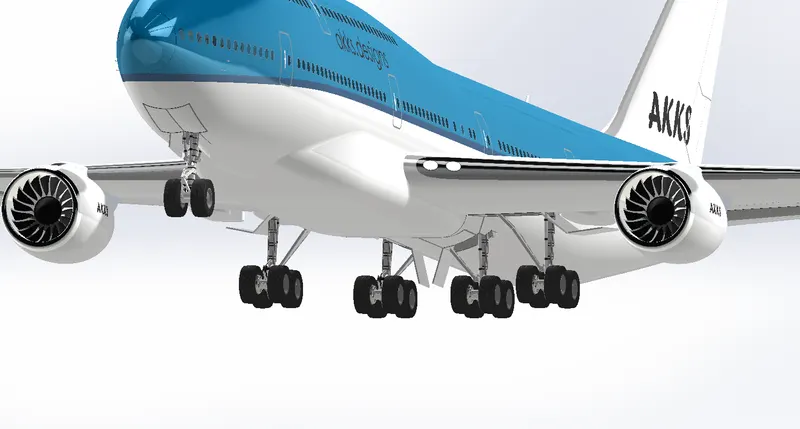
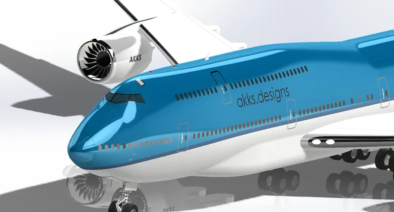
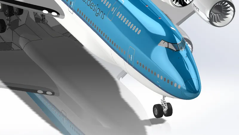
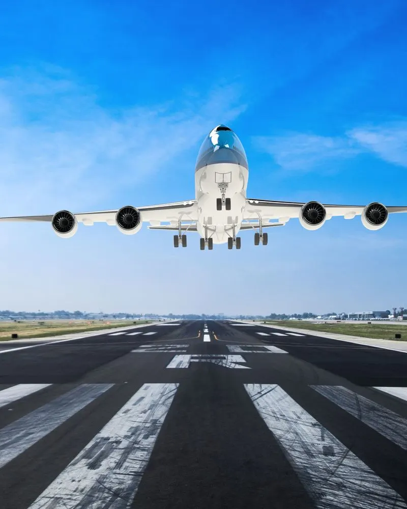
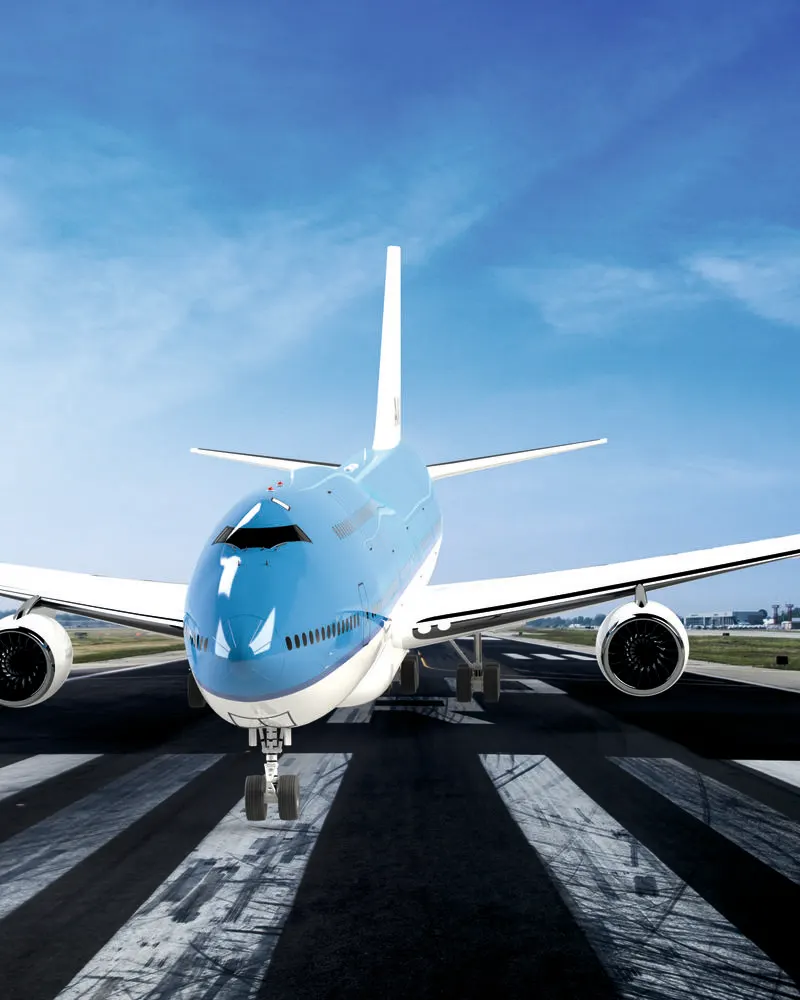
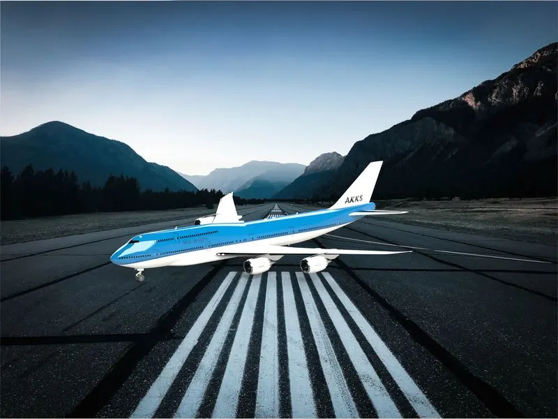
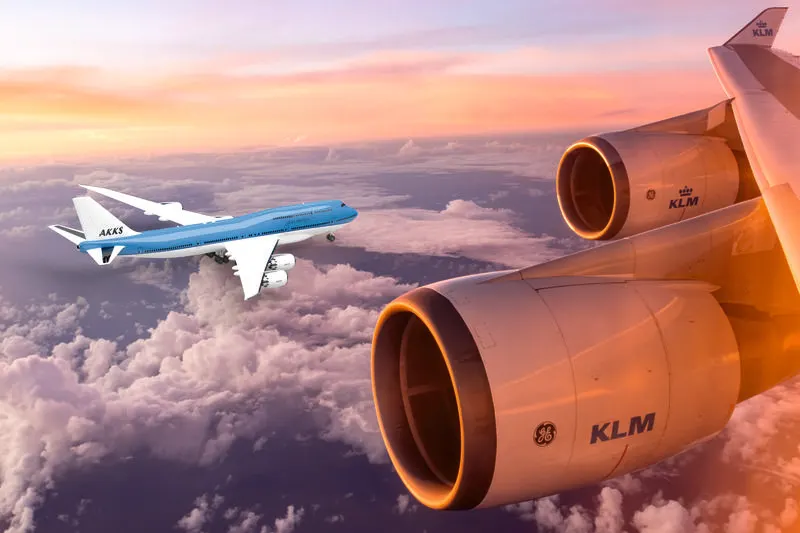
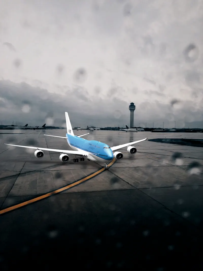
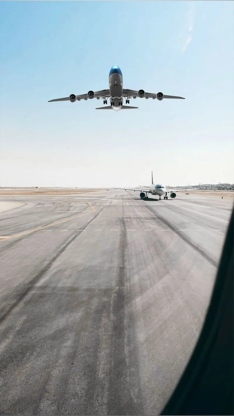
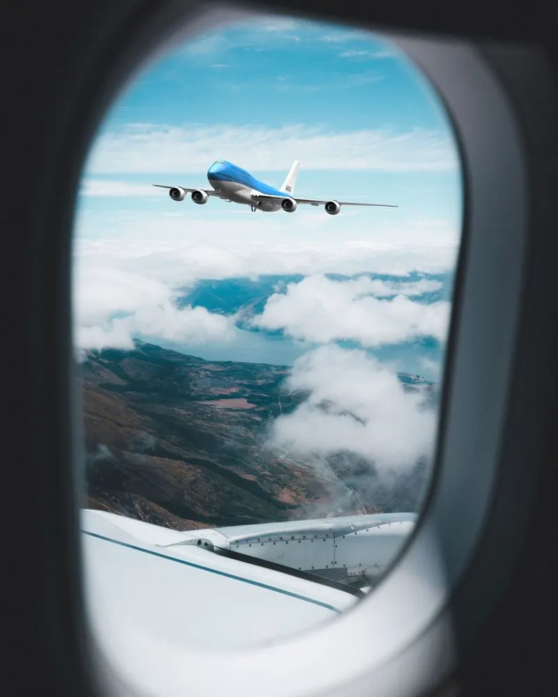
- To create photorealistic renders using SolidWorks Visualize.
INTRODUCTION
SolidWorks is a solid modeling computer-aided design (CAD) and computer-aided engineering (CAE) application published by Dassault Systèmes. It has other ADD-in features like photoview360 which helps in rendering modelS to make it look photo realistic. In this project we learnt about detailed design of Americal chopper parts and assemblig them and rendering the final after assembly.
The Boeing 747-8 is a wide-body airliner developed by Boeing Commercial Airplanes, the latest and largest variant of the 747. After introducing the 747-400, Boeing considered larger 747 versions as alternatives to Airbus A3XX. The stretched 747 Advanced was launched as the 747-8 on November 14, 2005, for a market forecast of 300 aircraft. The first 747-8F Freighter performed its maiden flight on February 8, 2010, and the passenger 747-81 Intercontinental followed suit on March 20, 2011. The cargo version was first delivered in October 2011 and the airliner began commercial service in June 2012.
The 747-8 was the first lengthened 747 to go into production and the second 747 version with a fuselage of modified length after the shortened 747SP.
The passenger version, named 747-8 was formally launched on November 14, 2005, by Boeing. It can carry up to 410 passengers in a typical three-class configuration over a range of 8,000 nmi (14.310 km) at Mach 0.855
Wing Span 68.45 m
Length 76.25 m
Height 19.35 m
Power Plant 4 x GEnx-2B67(296 KN)
Engine Model General Electric GEnx
DESIGN METHODOLOGY:
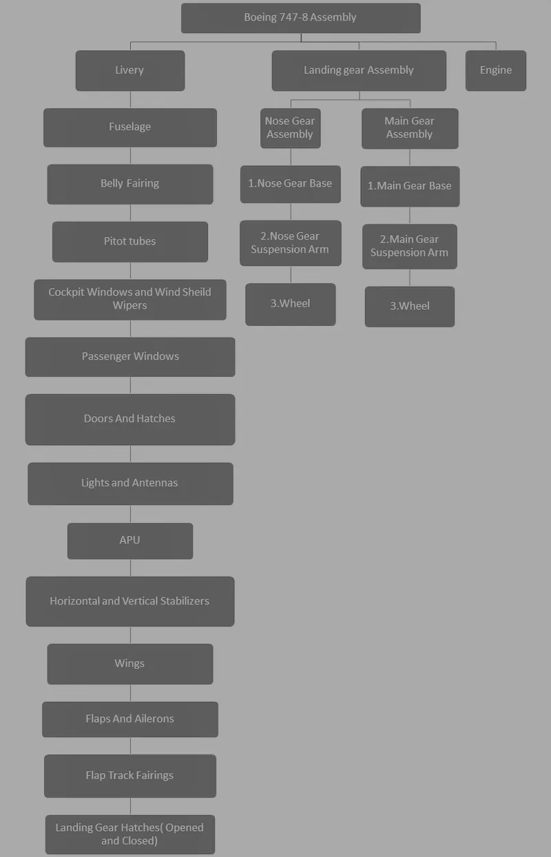
Here the Boeing 747-8 is assembled by following Bottom-up Approach. In this approach all the parts are modelled in individual part files and assembled together in a common assembly file. This method is generally used for off-the-shelf components which can be readily assembled in an assembly line. This approach makes it easy to configure individual components for different specifications.
SOLIDWORKS TOOLS AND FEATURES USED TO DESIGN Boeing-747
Fixing SKETCH for start any modeling:
2D TOOLS include in sketch are
- Line
- Circle
- Arc
- Spline
- Rectangle
- Circular Pattern
- Polygon
- Offset
- Fillet
- Mirror
- Ellipse
- Chamfer
- etc
(Each tool have their own unique uses also have contained more options)
Then using FEATURES we can change 2D sketch to any required 3D model objects and any desired item
- Blocks: We can save, edit and insert blocks from the drawing items and sketch entities that you use often such as standard notes, title blocks, label positions and so on you can attach blocks to geometry or to drawing views.
- Boss Extrude: Feature used for expand the object in 3D according to sketch plane.
- Revolve boss base: Feature is used to make cylindrical or circular 3D extrude along with a given reference axis as per drawn sketch.
- Extrude Cut: Extrude cut feature used to cut/remove the 3d object in linear path according to sketch.
- Revolve cut: Revolve cut is used to cut or reduce the extrude of cylindrical round surface.
- Lofted Boss/Base: Lofted boss is a feature used to achieve Complex Shapes. It does this by interpolating surfaces between various cross-sections of a model. These cross-sections can be sketches, faces, or edges.
- Sweep: This feature is used to sweep any kind of fully defined sketch along with the path.
- Sweep cut: Sweep cut is same as sweep feature but its directly proportional to sweep which makes a cut along with the sweep path.
- Linear Pattern: The linear parent is used to create a different number of instances required to create the pattern linearly.
- Circular pattern: Circular pattern is a feature used to make 3d feature into circular pattern according to number of insistences.
- Swept Surface: It is used to make a surface along with a path the curve is driven.
- Boundary Surface: Boundary surface is used to make a surface in between two finished surfaces.
- Curve Driven Pattern: Curve driven pattern is used to make any pattern which followed by the curve is sketched before.
- Curve Driven Pattern: Curve driven pattern is used to make any pattern which followed by the curve is sketched before.
- Loft Surface: Loft surface is used to make loft in between two profiles along with guide path.
- Knit surface: Knit surface is used to knit the two free edges or open edges of the surfaces together also it reduces the gap between the two edges of the surface.
- Move/copy body: This feature is used to move/copy the 3D body to one place to another place.
- Surface Trim: Primarily used to cut away material from a surface, and provides two modes: Standard and Mutual.
- Mirror: Mirror is used to mirror a feature or body by reference of the selected plane.
- Fillet: Fillet is a feature used for making round internal or external edges to avoid sharp edges and make it smooth.
- Chamfer: Chamfer is used to make a sharp edge or corner slightly tapered rather than being a perfect square.
- Split: Split tool is used to split single solid part into two solid parts. It is used to project an entity onto other surfaces or curved/planar faces.
- Dome: Dome is a feature used to make dome shaped extrude including elliptical dome.
- Shell: Shell feature is used to make to hollow space in solid part by selecting outer wall of the solid part and so removes the inner parts. It is also used to reduce the specific thickness.
- Combine: Combine tool is used to make integration of two solid parts which intersect each other as same solid part.
- Projection Curve: Projection curve is a 3D curve which is projected on the basis of the two different 2D curves in two different planes.
- Trim entities: it is used to trim the unwanted lines or extended entities in the sketch.
- Appearances: An appearance defines visual properties of the model including colour and texture. Appearances do not affect physical properties which are defined by materials. every material is a assigned a default appearance.
Sketch Entities:
- Line, circle, rectangle, arc, slot, spline.
- Convert entities- Create one or more curves in a sketch by projecting an edge, loop, face, curve or set of sketch curves on to the sketch plane.
- Trim and extend- cut the point over the sketch entity and move the point over the sketch entity to extend.
- Offset-offset line arc and splines if the original entity change the offset entity also change.
- Mirror- mirroring is another way that can create copy of an existing object choosing a plane or mirror face.
- Pattern- create multiple instances of one are more features that can space alone with pattern type.
Solid features:
- Boss Extrude = It is converting 2D sketch into 3D feature
- Cut extrude = cut extrude is similar to boss extrude but the difference it is cutting the 3D feature
- Sweep = Sweep features are defined by using custom 2D cross-section (or face) moved along a pre-set path to create a 3D shape or surface.
- Loft-Loft feature creates a shape by making transitions between multiple profile and guide curves. this tool is very valuable for modelling complex surface
- Revolve = Revolves add or remove material by revolving one or more profiles around a centreline.
- Shell =The shell tool hollows out a part, leaves open the faces you select, and creates thin-walled features on the remaining faces.
- Mirror = mirroring is another way that can create copy of an existing object choosing a plane or mirror face
Surface feature:
- Surface extrude = Using the Surface Extrude feature, it can extrude the boundary edges of a face or edges of a surface body in a customized direction.
- Surface trim = Create two or more surfaces that intersect at one or more points, or create a surface that intersects with a plane or has a sketch on its face.
- Thicken = Thicken takes a surface body (which has zero thickness) and makes it a solid by specifying a thickness value and side to thicken.
Common feature:
- Plane - Plane is reference for sketching and creating features.
- Curves - Curve as the path or guide curve for a sweep and loft feature, as a parting line for a draft feature.
- Dome - It creates a dome that is tangent to the adjacent cylindrical or conical face.
- Fillet - Create a rounded internal or external face on the part. selected faces, edges or edge loops.
- Split-use the split feature to create multiple parts from an existing part.
- Combine - Multiple bodies contained within one multibody part file.
- Split line - Tool projects an entity (sketch, solid, surface, face, plane, or surface spline) to surfaces, or curved or planar faces.
BOEING 747 PARTS:
- Blueprints
- Fuselage
- Belly fairing
- Nose cone
- Pitot tubes
- Cockpit window
- Passengers window
- Door & hatches
- Light & antenna
- Auxiliary power unit
- Vertical stabilizer
- Wing
- Flap & aileron
- Flap track fairing
- Landing gear hatches
- Wheel
- Nose gear
- Main gear
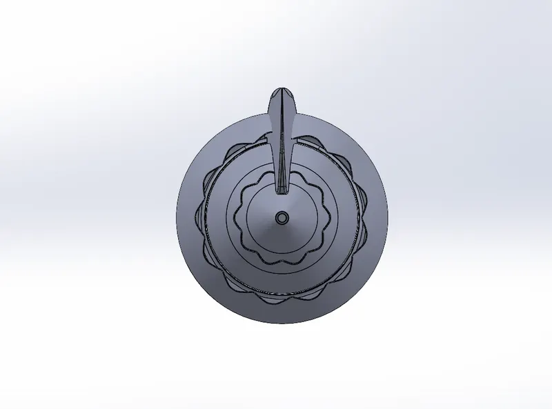
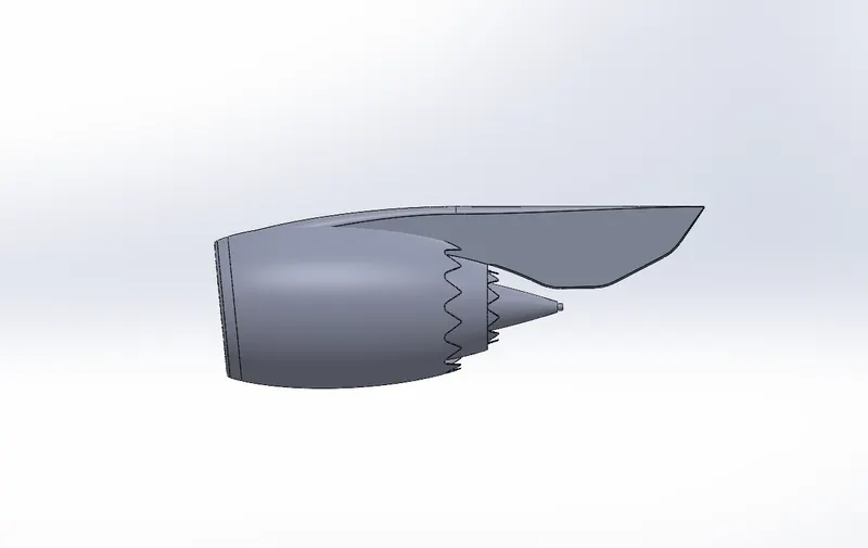
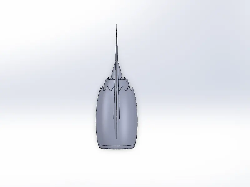
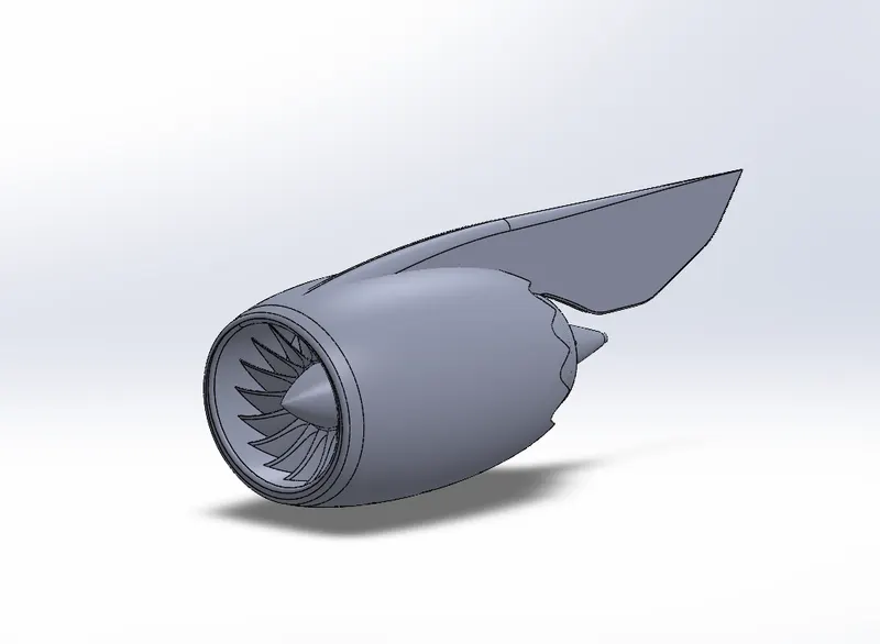
- Engine
Blueprint Set Up:
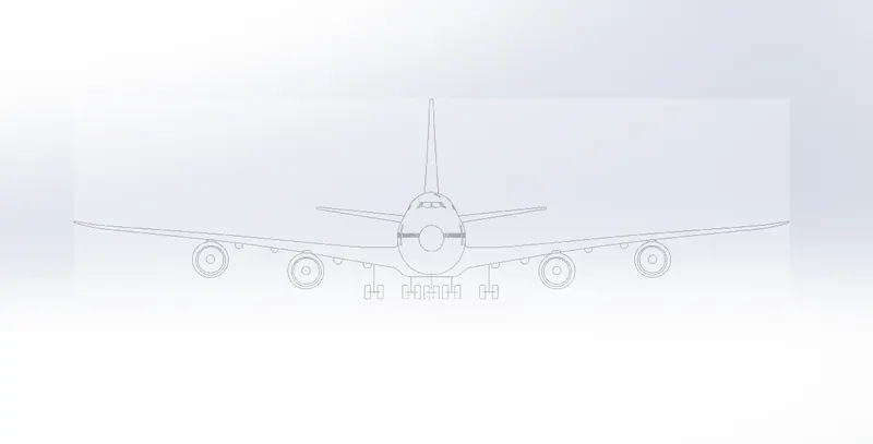
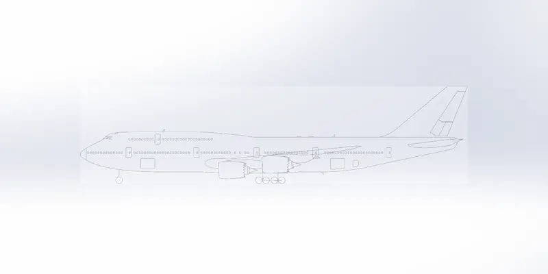
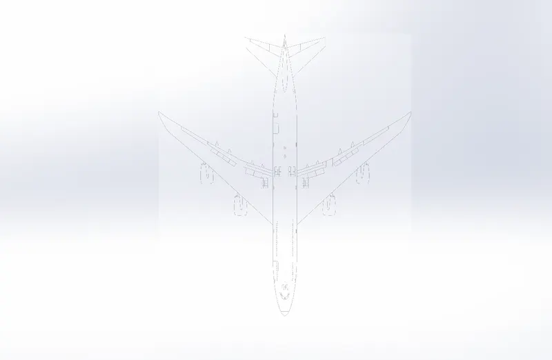
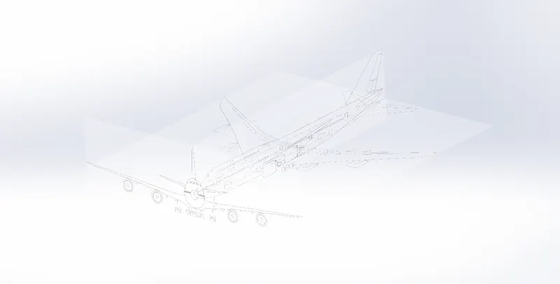
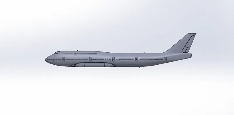
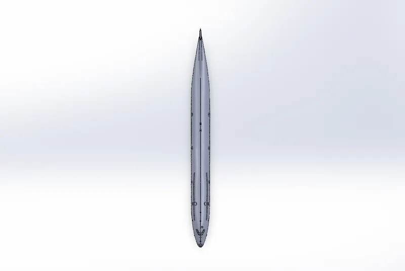
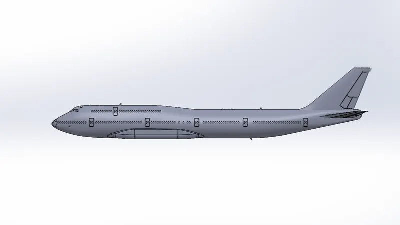
There are three different views (Front Side & Top) used in the Blueprint Setup. By using The Sketch Picture option, the images are inserted and the required dimensions are given to the images.
Views:
Isometric:
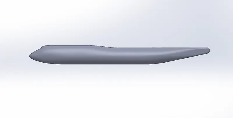
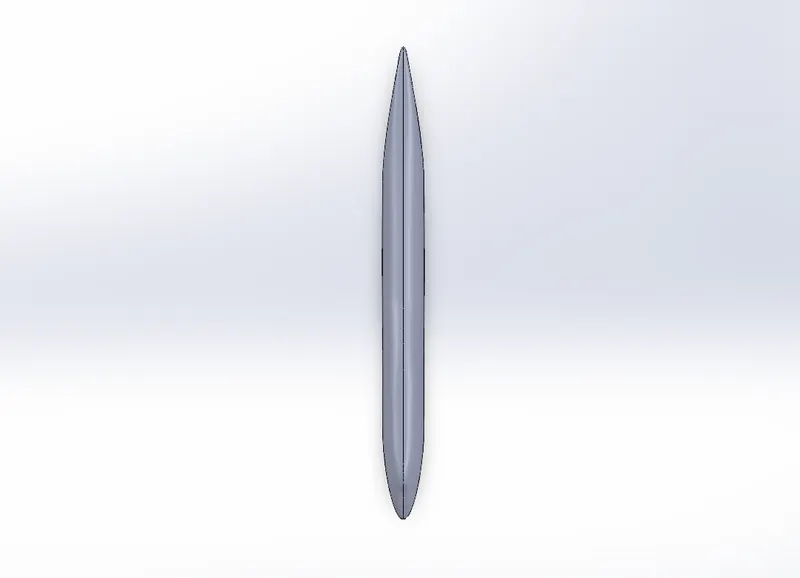
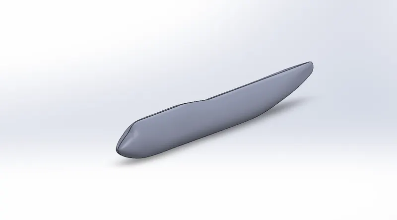
Fuselage
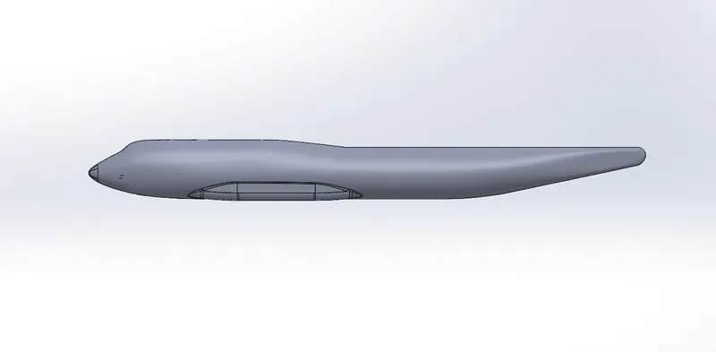
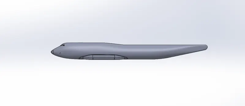
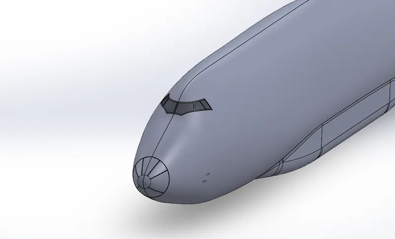
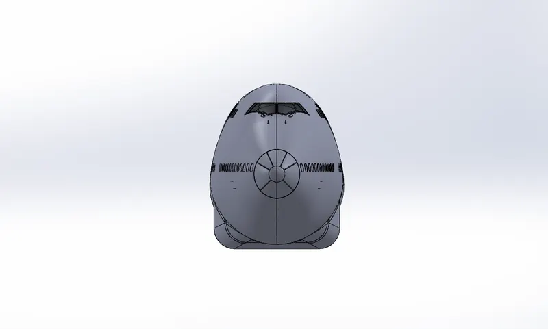
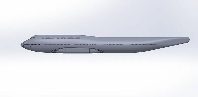
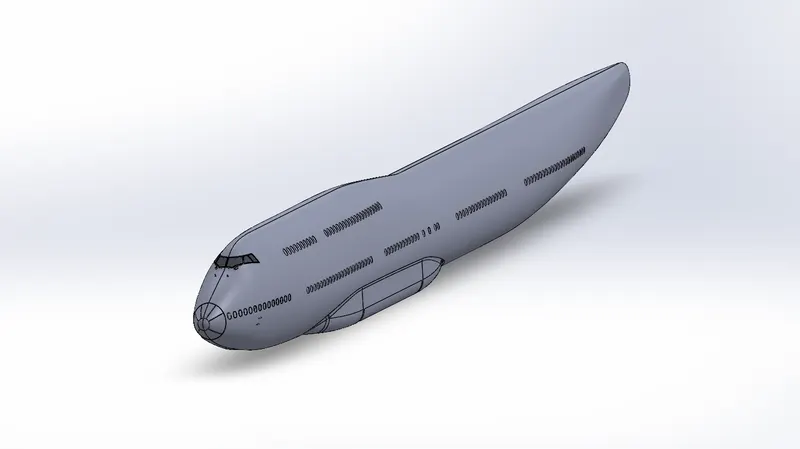
The Fuselage is an aircraft's main body section. It holds crew, passengers, and cargo. In single-engine aircraft, it will usually contain an engine, as well, although in some amphibious aircraft the single engine is mounted on a pylon attached to the fuselage, which in turn is used as a floating hull. The fuselage also serves to position control and stabilization surfaces in specific relationships to lifting surfaces, which is required for aircraft stability and manoeuvrability.
- Initially required Sketches are created for the Fuselage.
- Then by using the Surface Loft command the half side of the fuselage is created. Then the surface is mirrored to the other side by using the Mirror command.
- Then the Surface body is created as the solid body by using the Knit command.
- The fuselage, or body of the airplane, is a long hollow tube which holds all the pieces of an airplane together.
- The fuselage is hollow to reduce weight. As with most other parts of the airplane, the shape of the fuselage is normally determined by the mission of the aircraf.
Feature used
- Sketch entities
- Surface loft
- Mirror
Views:
Isometric:
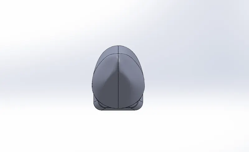
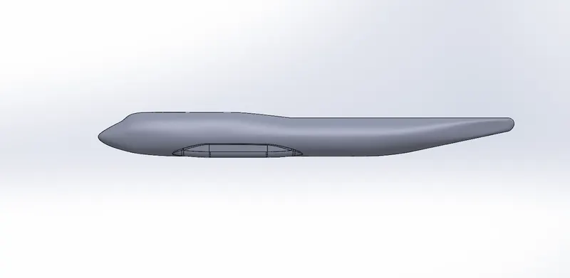
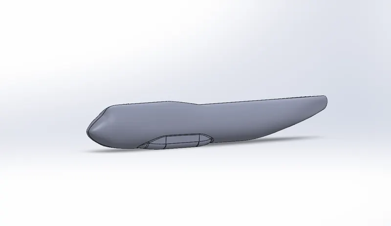
Belly fairing
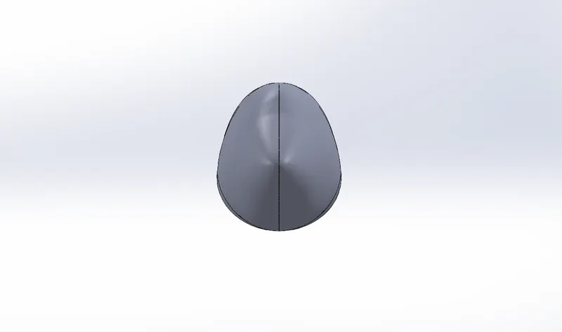
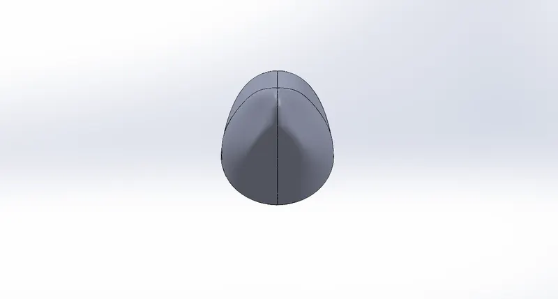
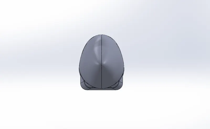
Belly Fairing also called a "ventral fairing, it is located on the underside of the Fuselage between the main Wings. It can also cover additional cargo storage or fuel tanks.
In an aircraft comprising a fuselage and a belly fairing, the fairing is made of two independent parts. For example, a first part of the fairing comprises a front section, a central section and a first portion of a rear section. A second part of the fairing comprises a second portion of the rear section. The second part can shift relative to the first part of the fairing. Also disclosed is a belly fairing for aircraft comprising two independent parts.
Belly fairing is created using Boss Extrude, Fillet, Mirror and Combine Command.
- Belly fairing. Also called a “ventral fairing”, it is located on the underside of the fuselage between the main wings. It can also cover additional cargo storage or fuel tanks.
Feature used
- Boss Extrude
- Fillet
- Split line
- Mirror
- Combine
Isometric:
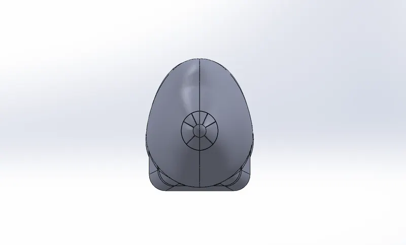
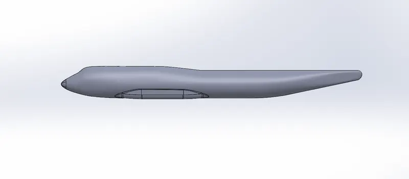
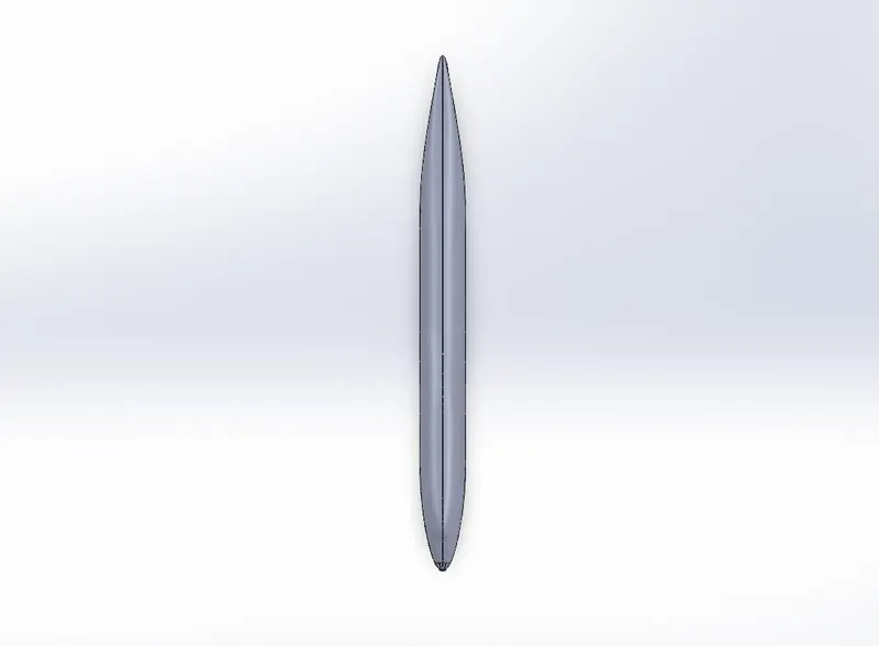
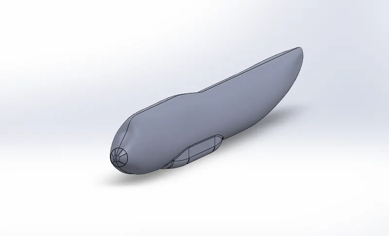
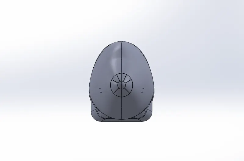
Nose cone
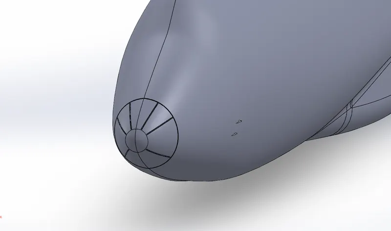
Found at the foremost point of an aircraft, a nose cone must be aerodynamic in order to reduce drag on a plane. On most commercial and military aircraft, the nose cone also houses radar and other instruments that might be used to detect meteorological phenomena, track enemy aircraft or transmit communication signals.
The Ribs which are available in the Nose cone are conductive strips drain stack electricity to the middle hole aft of the cone. Nose itself is made of quartz insulator.
On airliners the nose cone is also used for protecting the weather radar from aerodynamic forces.
- The nose of an airplane is very important to flight. Like the tip of an arrow, it decides where the plane is going to go.
- All of the elements of flight depend on keeping the nose pointed in the right direction.
Feature used
- Split line
- Sweep
- Mirror
- Fillet
Views:
Isometric:
Pitot tubes
Pitot tubes are also known as pitot probes. Pitot tube is a flow measurement device used to measure fluid flow velocity Pitot tube is widely used to determine the air speed of the aircraft.
Basically, a pitot tube is used in wind tunnel experiments and on airplanes to measure flow speed. It's a slender tube that has two holes on it. The side hole measures the static pressure. By measuring the difference between these pressures, you get the dynamic pressure, which can be used to calculate airspeed.
There are four pitot tubes available in the Boeing 747-8 Aircraft. Two pitot tubes are placed in the right side of the aircraft and other two on the other side of the aircraft.
The Pitot-static system is used to determine and display
- Airspeed
- Mach number
- Altitude trend
Large Pitot-static system errors can be hazardous
- Pitot tubes are crucial components onboard aircraft used to measure a range of important data.
- The tubes are popularly known as speedometers.
Feature used
- Boss Extrude
- Cut extrude
- Fillet
- Mirror
- Chamfer
Views:
Isometric:
Cock pit window
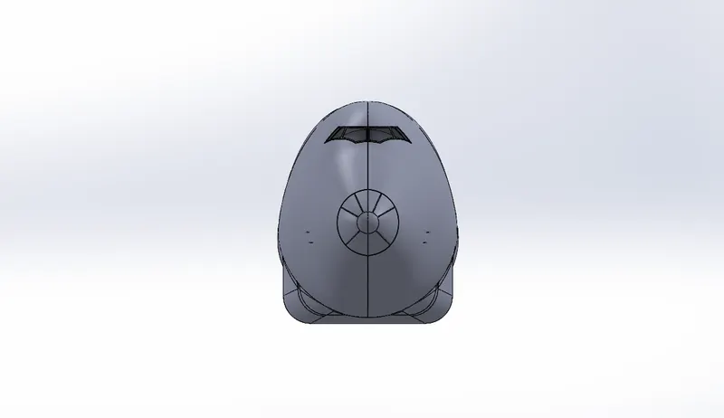
A cockpit or flight deck is the area, usually near the front of an aircraft or spacecraft, from which a pilot controls the aircraft.
The cockpit is the section where the pilot and the co-pilot manage the aircraft. The two main functions of the cockpit are; to provide the pilot with a good angle and to make all control mechanisms accessible to them. Planes are also designed based on the same principle of any vehicle.
The cockpit of the plane is where the plane is controlled. This section is like an office for pilot and co-pilot. All data is transmitted to the pilot and co-pilot with the help of panels within this section to ensure that the aircraft can fly stably. This is also a special section equipped with security systems, by which the aircraft is controlled. Thus, the cockpit provides every data about the plane and is designed to give the pilots a good angle during flight.
Function of cockpit:
The cockpit is the section where all data about aircraft and flight is transmitted to pilots via screens. The aircraft can be manually managed thanks to the control mechanisms within this section. There are also communication panels. All information about the plane is sent to the control towers through this system. The cockpit windows are made from laminated thermally tempered glasses sand- wiched with urethane and vinyl (PPG is one of the major suppliers of cockpit or window transparencies). Often three sheets of 6 mm toughened glass with thick PVB (Poly Vinyl Butyric) are used.
- Boeing windows aren’t made from your run of the mill glass.
- Instead, they are constructed from special polymers and plastic.
Feature used
- Split line
- Surface offset
- Thicken
- Fillet
Views:
Isometric:
Passenger windows
A cabin window consists of three panes,
- An outer pane flush with the outside fuselage.
- An inner pane-Which has a little hole in it.
- A thinner non-structural plastic pane called scratch pane.
The main thing to know in the aircraft cabin windows are not made of glass, but with something called "stretched acrylic.
Boeing 747-8 aircraft has 250 passenger windows. The outer pane is 12mm thick and the inner pane 4mm thick. They are separated by a 6mm edge chamfer.
- many passenger cabin windows, flight deck windows are built with multiple plies of glass or stretched acrylic material.
Feature used
- Split line
Views:
Isometric:
Door & hatches
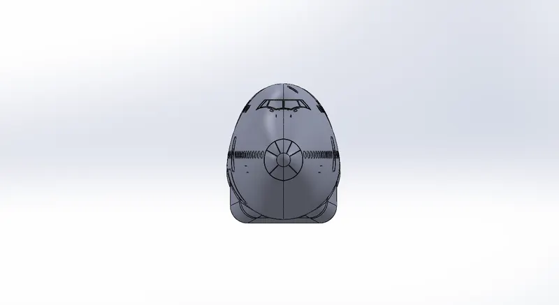
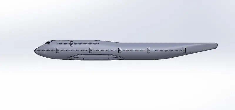
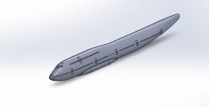
There are 6 doors on each side of the Boeing 747-8. The top above the cockpit the cockpit escape hatch is placed. On the right side of the fuselage there are 3 hatches available. One at the front two at the rear side of the fuselage. The plug door is often seen on aircraft with pressurized cabins. Due to the air pressure within the aircraft cabin being higher than that of the surrounding with multiple pins or hatch dogs to prevent opening while in flight.
Feature used
- Split line
- Linear pattern
- Surface offset
- Thicken
- Fillet
Views:
Isometric:
Light & antenna
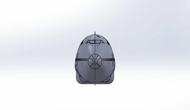
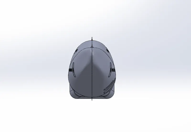
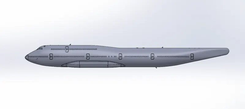
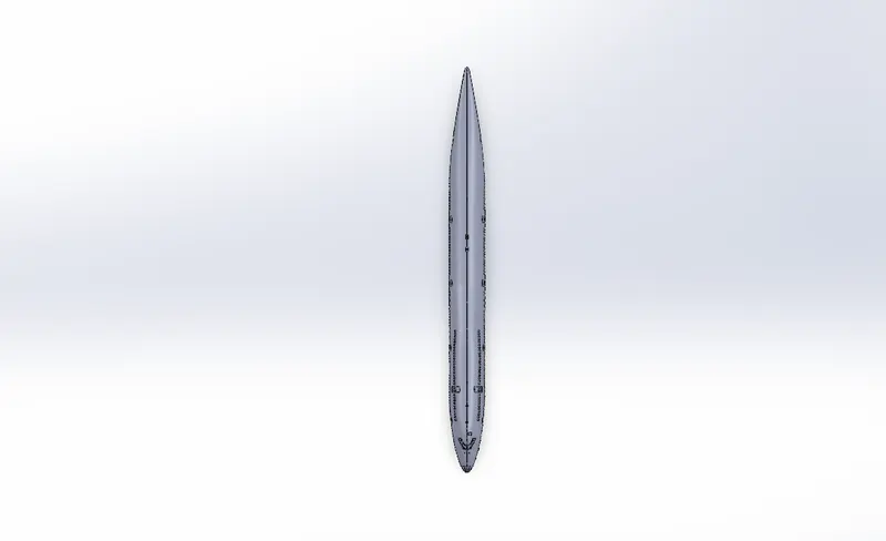
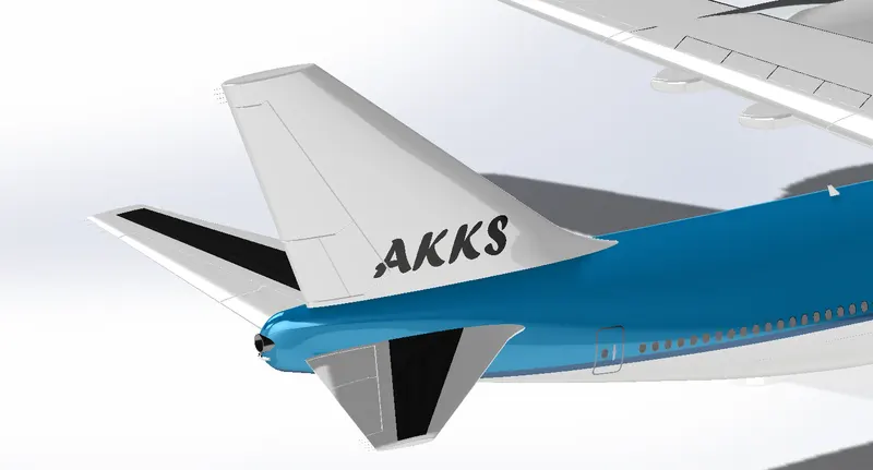
There are 2 lights and 3 antennas as created in the Boeing 747-8 mode. The lights are on the back side of the cockpit. The two antennas are in the top of the fuselage and one in the beneath of the fuselage.
Aircraft use collision avoidance lighting systems to warn other aircraft of their presence. These lights include landing lights, red or white flashing beacons, wingtip strobes, and wingtip navigation lights. The wingtip navigation lights are required to consist of a red light on the left wingtip and a green light on the right wingtip. Landing lights are used during the descent and approach to landing, and at other times if deemed necessary by the flight crew or operator.
Most aircraft VHF communications antennas are Marconi antennas. They are vertically polarized and create a field that is omnidirectional. On fabric skinned aircraft, the ground plane that makes up the second one-fourth wavelength of the antenna must be fashioned under the skin where the Marconi antenna is mounted.
There are different types of antennas available in the aircraft. The following are the common antennas available,
- Communications Antennas
- GPS Antennas
- Loran Antennas
- Loop Antennas
- Marker Beacon Antennas
- Nav Antennas
- Radio Altimeters
- UHF Antennas
- The red and green lights found on the wingtips of airplanes are known as navigation lights.
- They are designed to increase the airplane's visibility to other pilots, as well as air traffic controllers on the ground, to minimize the risk of collision. Navigation lights don't emit any signals.
- The antenna at the transmitter generates the radio wave.
- A voltage at the desired frequency is applied to the antenna.
- The voltage across the antenna elements and the current through them create the electric and magnetic waves, respectively.
Feature used
- Revolve
- Linear pattern
- Boss extrude
- Draft
- Split line
- Surface offset
- Thicken
- fillet
Views:
Auxiliary power unit
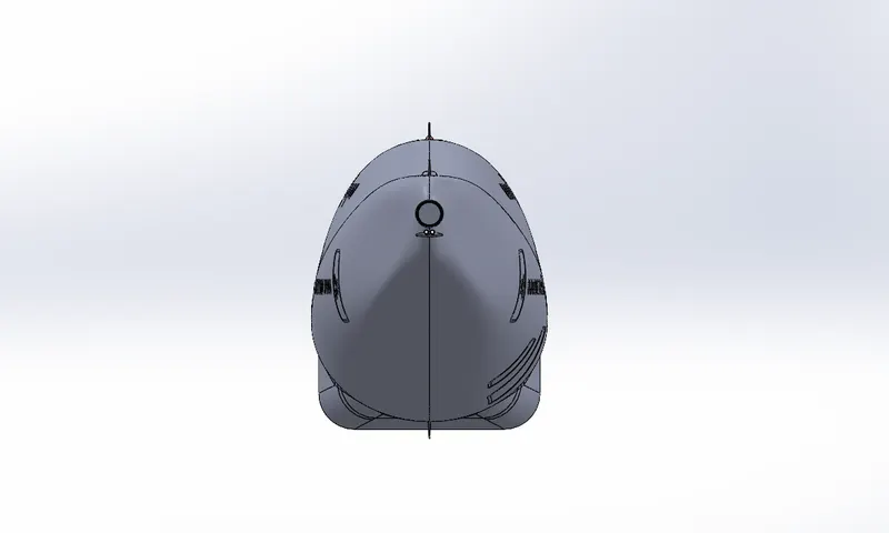
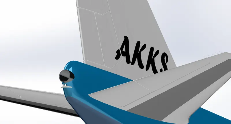
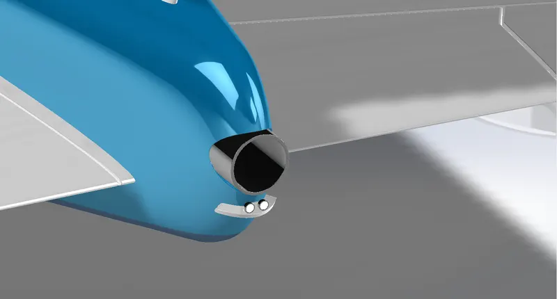
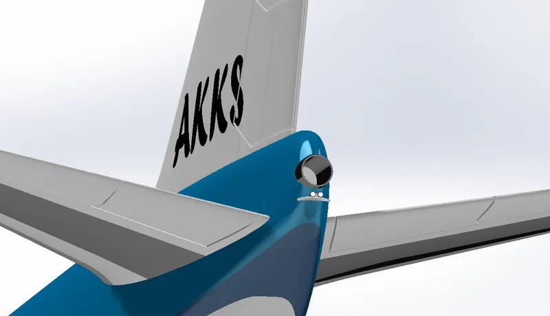
An auxiliary power unit (APU) is a device on a vehicle that provides energy for functions other than propulsion. They are commonly found on large aircraft and naval ships as well as some large land vehicles.
An aircraft auxiliary power unit serves as an additional energy source normally used to start one of the main engines on an airliner or business jet. The APU is equipped with an extra electrical generator to create enough power to operate onboard lighting, galley electrics and cockpit avionics, usually while the aircraft is parked at the gate. Drawing bleed air from its own compressor, an APU also drives the environmental packs used to heat and cool the aircraft.
And most important, operating an APU negates the need to start one of the aircraft's main engines while waiting for passengers to arrive. thereby saving on fuel and maintenance for a more expensive power plant.
APU produces 150 Volts 400 to 500 Hertz current to operate the aircraft systems.
- An auxiliary power unit (APU) is a device on a vehicle that provides energy for functions other than propulsion.
- It provides bleed air for cabin conditioning from a low spool-driven load compressor, and electrical power from two gearbox-mounted 90kVA generators.
Feature used
- Cut extrude
- Boss extrude
- Split line
- Surface offset
- Thicken
- Mirror
- Fillet
Views:
Isometric:
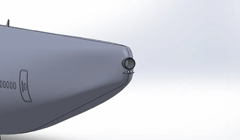
Vertical & Horizontal stabilizer
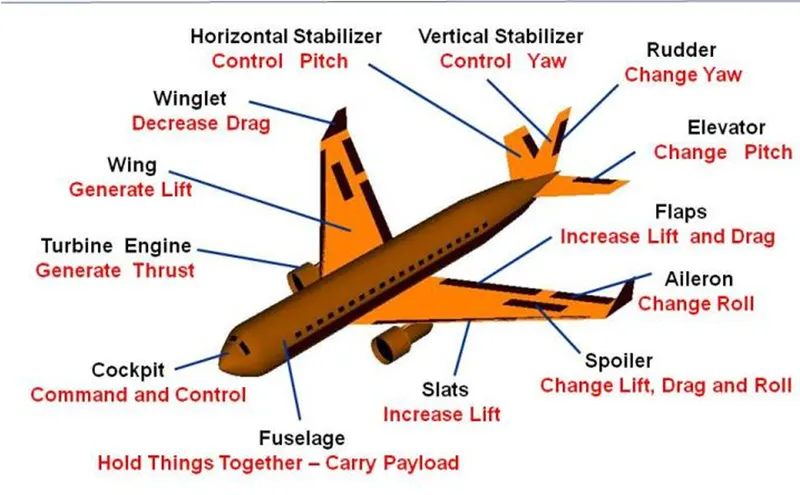
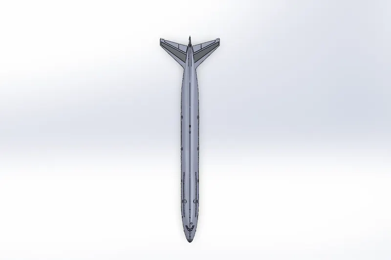
The stabilizers job is to provide stability for the aircraft, to keep it flying straight. The vertical stabilizer keeps the nose of the plane from swinging from side to side, which is called yaw. The horizontal stabilizer prevents an up- and down motion of the nose, which is called pitch.
A vertical stabilizer, vertical stabiliser, or fin of an aircraft, missile, bomb, or car are typically found on the aft end of the fuselage or body, and are intended to reduce aerodynamic side slip and provide direction stability. It is analogous to a skeg on boats and ships.
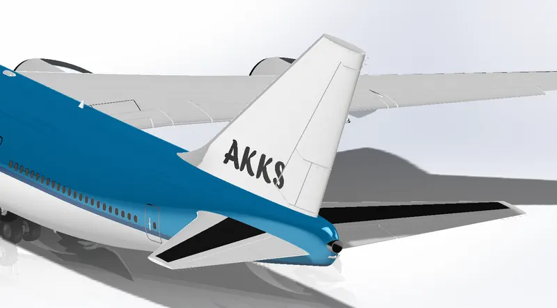
On aircraft. vertical stabilizers generally point upwards. These are also known as the vertical tail, and are part of an aircraft's empennage. This upright mounting position has two major benefits: The drag of the stabilizer increases at speed, which creates a nose-up moment that helps to slow down the aircraft and prevent dangerous overspeed; and when the aircraft banks, the stabilizer produces lift which counters the banking moment and keeps the aircraft upright in the absence of control input. If the vertical stabilizer was mounted on the underside, it would produce a positive feedback whenever the aircraft dives or banks, which is inherently unstable. The trailing end of the stabilizer is typically movable, and called the rudder, this allows the aircraft pilot to control yaw.
At the rear of the fuselage of most aircraft one finds a horizontal stabilizer and an elevator. The stabilizer is a fixed wing section whose job is to provide stability for the aircraft, to keep it flying straight. The horizontal stabilizer prevents up-and-down, or pitching, motion of the aircraft nose.
The elevator is the small moving section at the rear of the stabilizer that is attached to the fixed sections by hinges. Because the elevator moves, it varies the amount of force generated by the tail surface and is used to generate and control the pitching motion of the aircraft. There is an elevator attached to each side of the fuselage. The elevators work in pairs: when the right elevator goes up, the left elevator also goes up. This slide shows what happens when the pilot deflects the elevator.
- The stabilizer is a fixed wing section whose job is to provide stability for the aircraft, to keep it flying straight.
- The horizontal stabilizer prevents up-and-down, or pitching, motion of the aircraft nose.
feature used
- Loft
- Boss extrude
- Cut extrude
- Surface offset
- Thicken
- Fillet
- Mirror
Views:
Isometric:
Wings
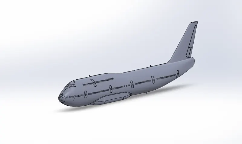
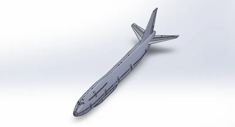
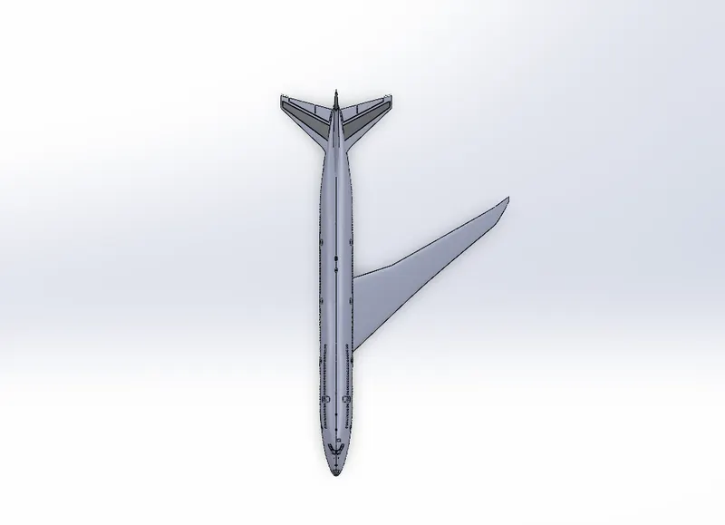
A wing is a type of fin that produces lift, while moving through air or some other fluid. As such, wings have streamlined cross-sections that are subject to aerodynamic forces and act as aerofoils. A wing's aerodynamic efficiency is expressed as its lift-to-drag ratio. The lift a wing generates at a given speed and angle of attack can be one to two orders of magnitude greater than the total drag on the wing. A high lift-to-drag ratio requires a significantly smaller thrust to propel the wings through the air at sufficient lift.
An airfoil or aerofoil is the shape of a wing, blade (of a propeller, rotor, or turbine), or sail (as seen in cross-section).
Aircraft wings may feature some of the following:
- A rounded leading-edge cross-section.
- A sharp trailing edge cross-section.
- Leading-edge devices such as slats, slots, or extensions.
- Trailing-edge devices such as flaps or flaperons (combination of flaps and ailerons) Winglets to keep wingtip vortices from increasing drag and decreasing lift.
- Dihedral, or a positive wing angle to the horizontal, increases spiral stability around the roll axis, whereas anhedral, or a negative wing angle to the horizontal, decreases spiral stability.
- The wings generate most of the lift to hold the plane in the air.
- To generate lift, the airplane must be pushed through the air.
- The air resists the motion in the form of aerodynamic drag.
- Modern airliners use winglets on the tips of the wings to reduce drag.
- The turbine engines, which are located beneath the wings, provide the thrust to overcome drag and push the airplane forward through the air.
Feature used
- Loft
- Surface offset
- Surface cut
- Fillet
Views:
Flaps & Ailerons
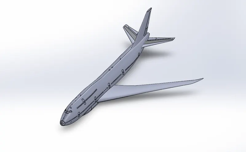
A flap is a high-lift device used to reduce the stalling speed of an aircraft wing at a given weight. Flaps are usually mounted on the wing trailing edges of a fixed-wing aircraft. Flaps are used to reduce the take-off distance and the landing distance. Flaps also cause an increase in drag so they are retracted when not needed.
The flaps installed on most aircraft are partial-span flaps: spanwise from near the wing root to the inboard end of the ailerons. An aileron is a hinged flight control surface usually forming part of the trailing edge of each wing of a fixed-wing aircraft.
Ailerons are used in pairs to control the aircraft in roll (or movement around the aircraft's longitudinal axis). which normally results in a change in flight path due to the tilting of the lift vector. Movement around this axis is called ' rolling' or ' banking
Boeing 747-8 has two flaps and two ailerons in both the wings.
- Flaps are deployed downward on take off and landing to increase the amount of force produced by the wing. On some aircraft, the front part of the wing will also deflect.
Feature used
- Cut extrude
- Split line
- Surface offset
- Thicken
- Fillet
Views:
Isometric:
Flap track fairing
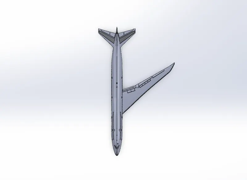
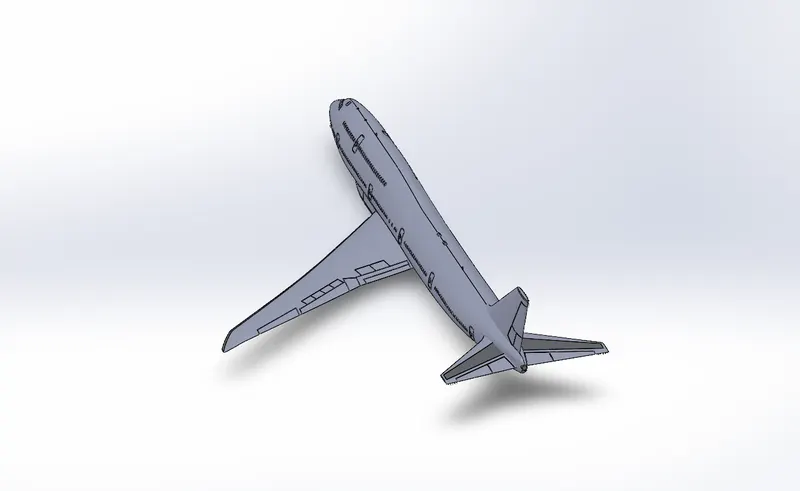
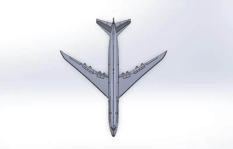
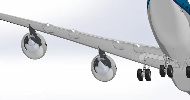
A flap is a high-lift device used to reduce the stalling speed of an aircraft wing at a given weight. Flaps are usually mounted on the wing trailing edges of a fixed-wing aircraft. Flaps are used to reduce the take-off distance and the landing distance. Boeing 747-8 has 8 flap track fairings 4 in the right-side wing and 4 in the left side wing.
Feature used
- boss extrude
- split
- combine
- fillet
- mirror
Views:
Isometric:
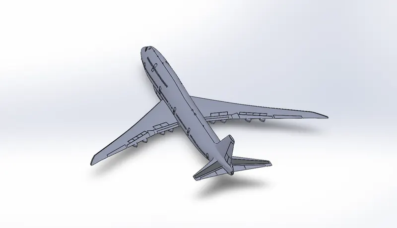
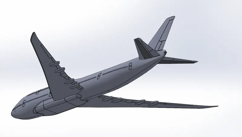
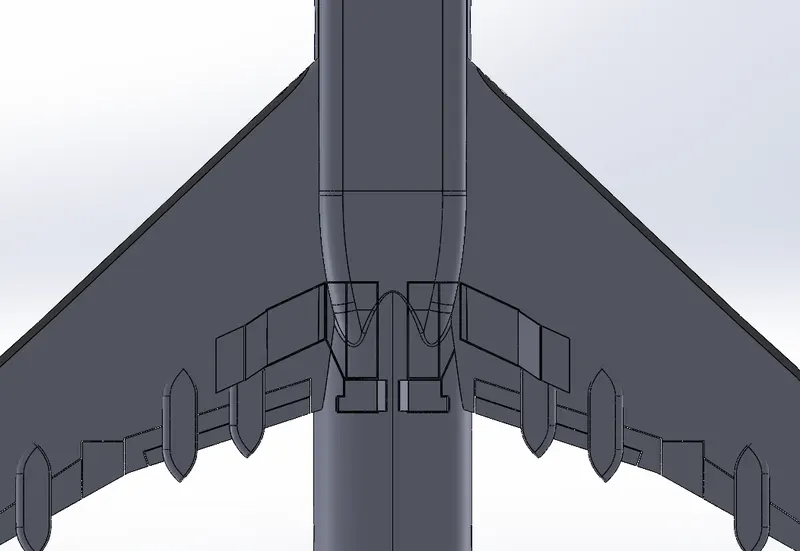
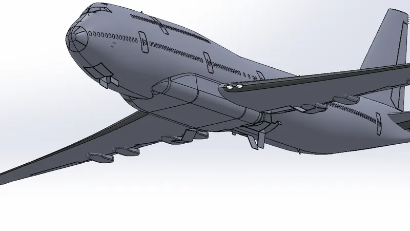
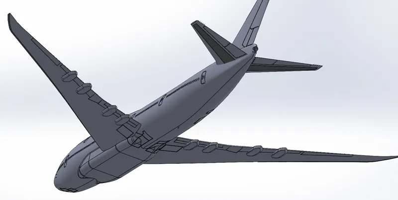
Landing gear hatches closed & open
Landing gear is the undercarriage of an aircraft or spacecraft and may be used for either take-off or landing. For aircraft it is generally needed for both. It was also formerly called alighting gear by some manufacturers, such as the Glenn L. Martin Company. For aircraft, Stinton makes the terminology distinction undercarriage.
For aircraft, the landing gear supports the craft when it is not flying, allowing it to take off, land, and taxi without damage. Wheeled landing gear is the most common with skis or floats needed to operate from snow/ice/water and skids for vertical operation on land. Faster aircraft have retractable undercarriages, which fold away during flight to reduce drag.
Some unusual landing gear have been evaluated experimentally. These include: no landing gear (to save weight), made possible by operating from a catapult cradle and flexible landing deck, air cushion (to enable operation over a wide range of ground obstacles and water/snow/ice). tracked (to reduce runway loading).
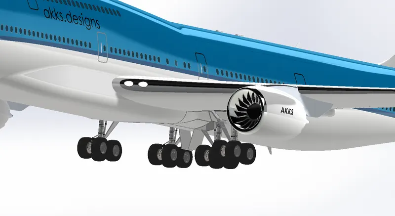
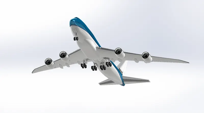
Landing Gear hatches will be basically open when the aircraft landings. This will be in the open condition only when the aircraft is in the land. The landing gear hatches will be closed once the aircraft takes off, the landing gear goes inside and the hatches will be closed.
Feature used
- split line
- surface offset
- Thicken
- Thicken
- Cut extrude
- Surface sweep
- Fillet
Views:
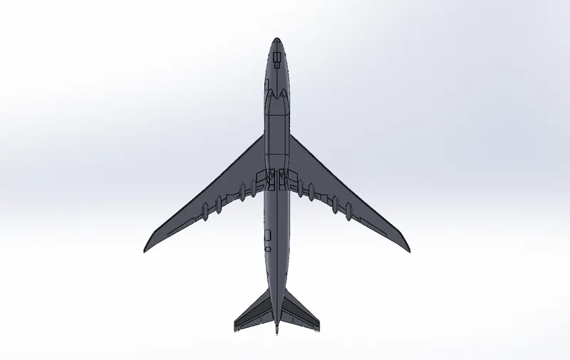
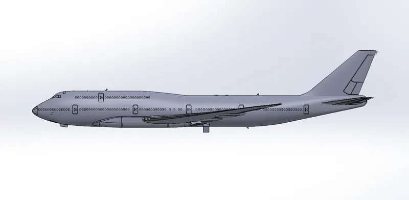
Isometric:
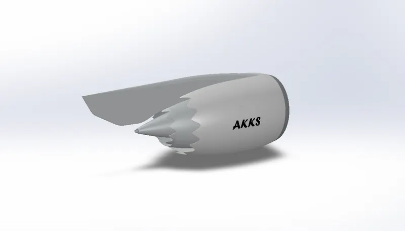
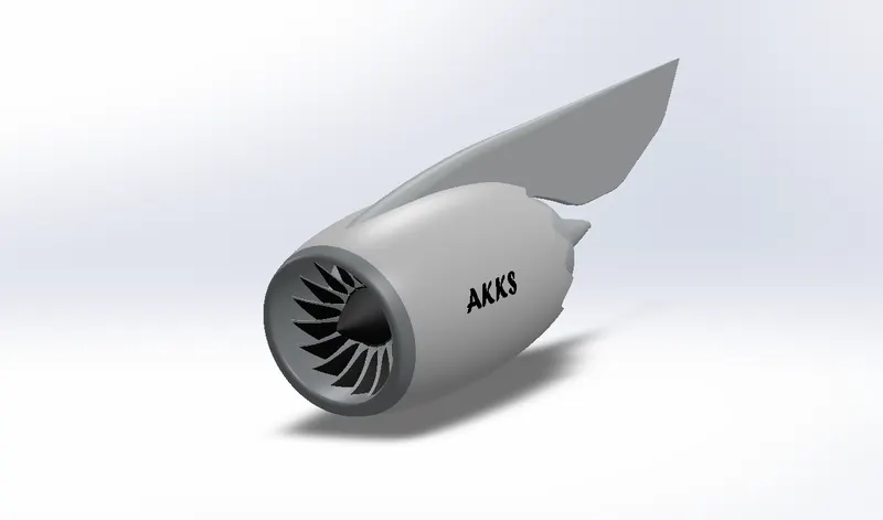
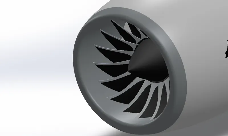
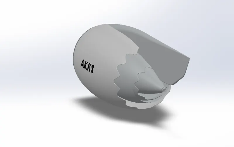
Engine:
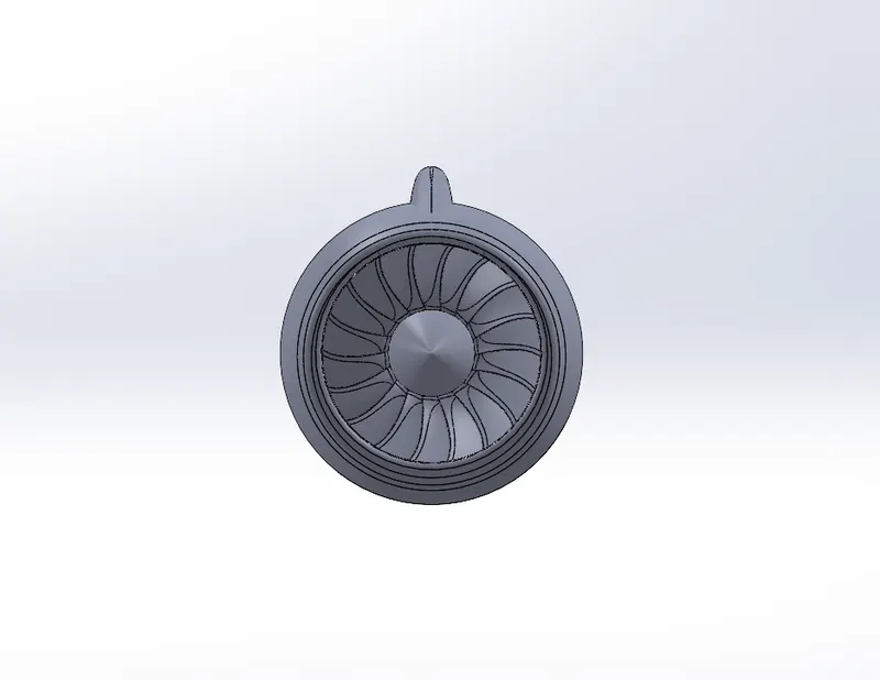
An aircraft engine, often referred to as an aero engine, is the power component of an aircraft Air propulsion system. Most aircraft engines are either piston engines or gas turbines, although in recent years many small UAVs have used electric motors.
In commercial aviation the major Western manufacturers of turbofan engines are Pratt & Whitney, General Electric, Rolls-Royce, and CFM International
A turbojet is a type of gas turbine engine that was originally developed for military fighters during World War II. A turbojet is the simplest of all aircraft gas turbines. It consists of a compressor to draw air in and compress it, al combustion section where fuel is added and ignited, one or more turbines that extract power from the expanding exhaust gases to drive the compressor, and an exhaust nozzle that accelerates the exhaust gases out the back of the engine to create thrust.
"The engine provides 66,500lb of thrust."... The engine selected for the aircraft is the GEnx-2867, the General Electric next-generation engine. The design of the 747-8 aircraft engine is a slightly modified variant of the GEnx engine developed for the Boeing 787 Dreamliner aircraft. The engine provides 66,500lb of thrust.
Views:
Isometric:
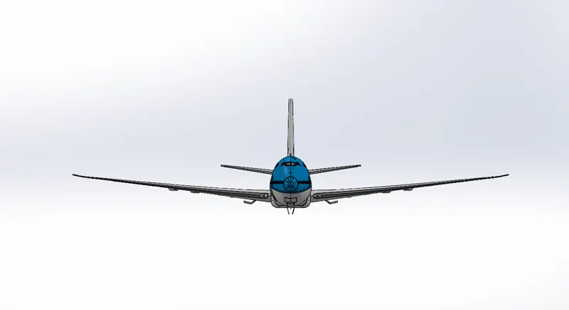
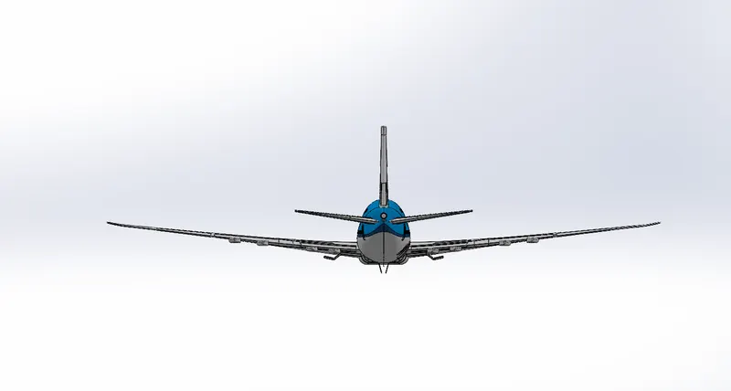
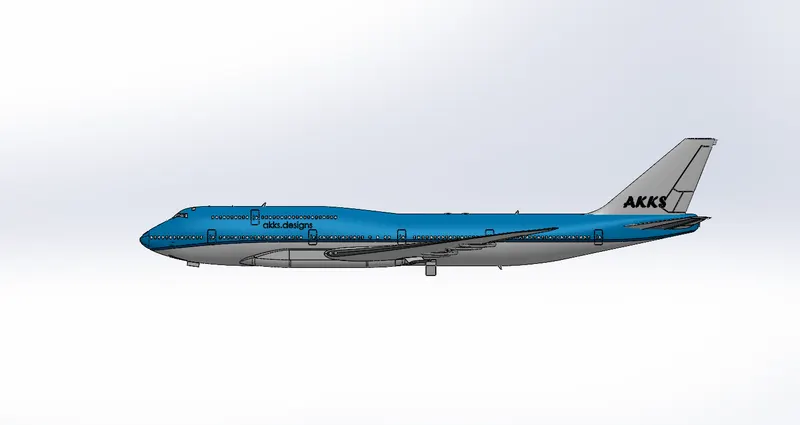
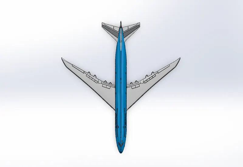
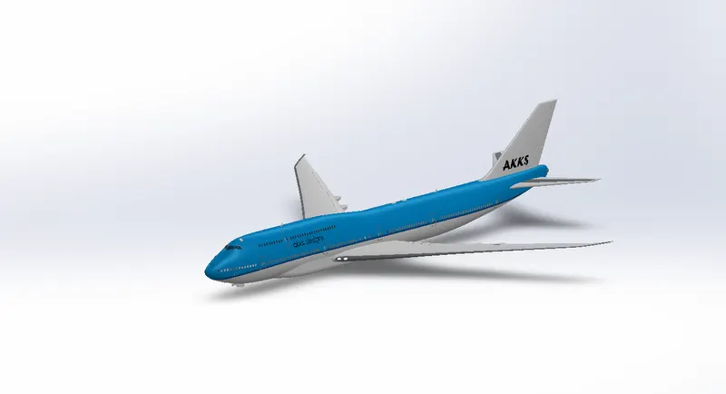
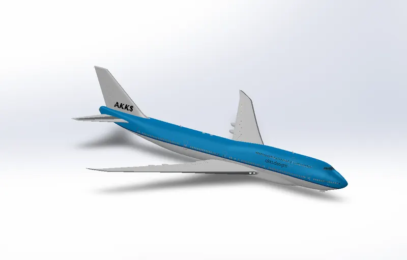
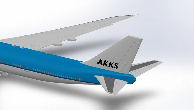
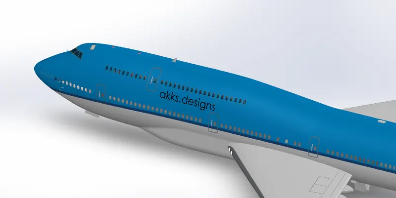
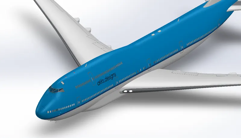
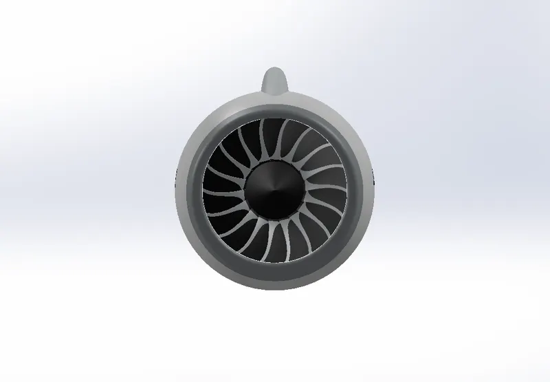
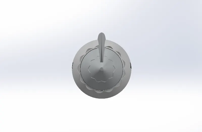
Livery:
An aircraft livery is a set of comprehensive insignia comprising color, graphic, and typographical identifiers which operators (airlines. governments, air forces and occasionally private and corporate owners) apply to their aircraft.
Livery of Main Body:
View:
Isometric:

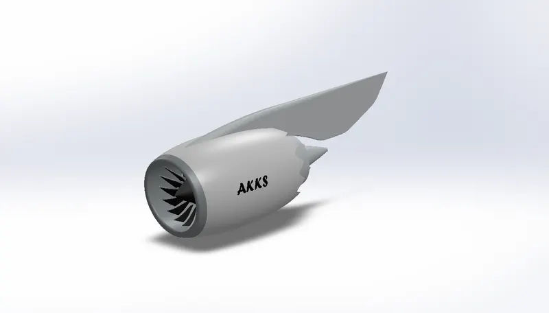
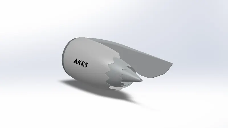
Livery of Engine:
Views:
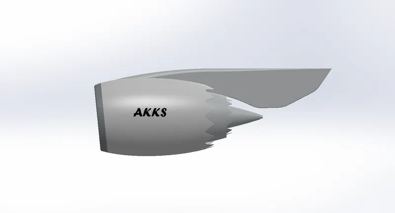
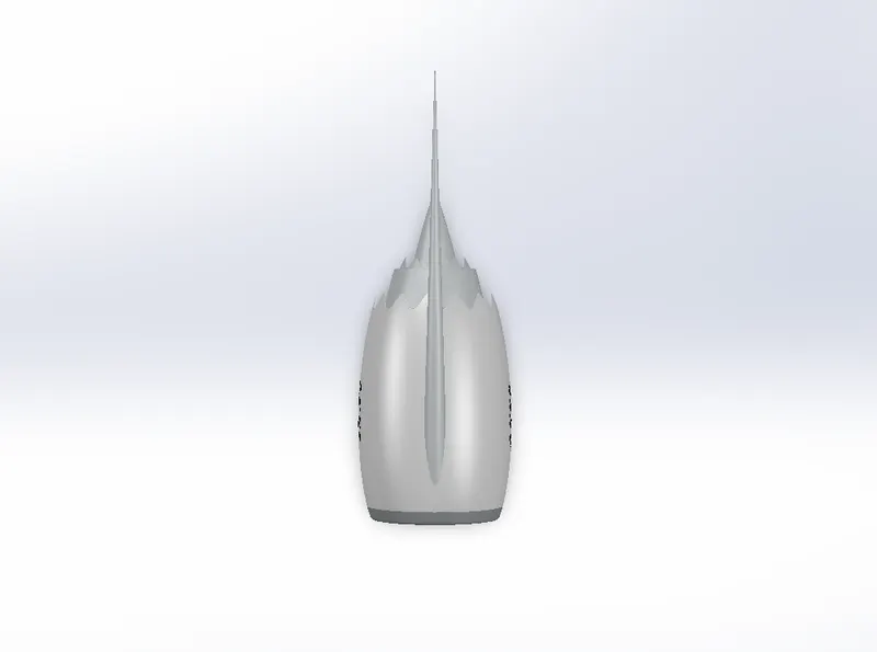
Isometric:
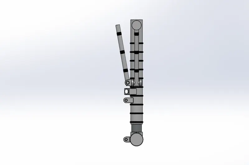
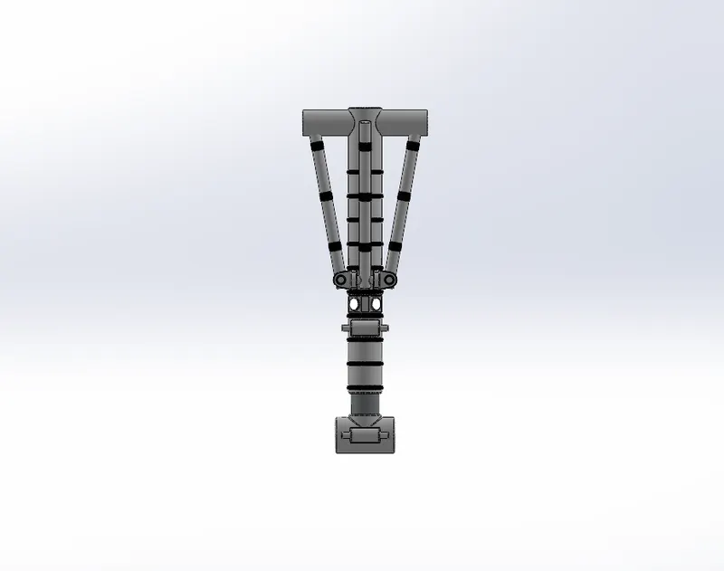
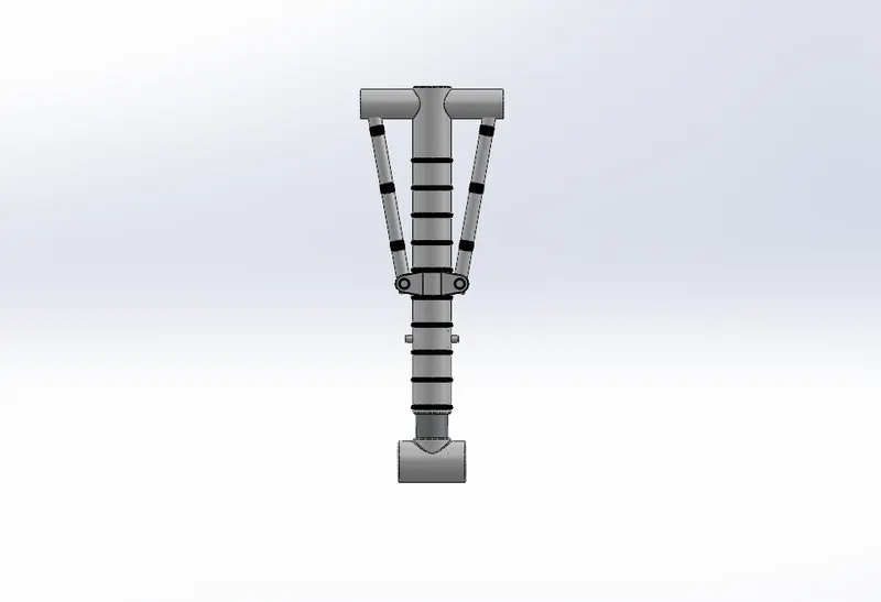
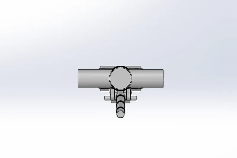
Nose gear
- The landing gear in the nose of an aircraft is called the nose gear.
- Nose gear is the name given to the landing gear in the nose of an airplane.
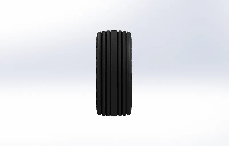
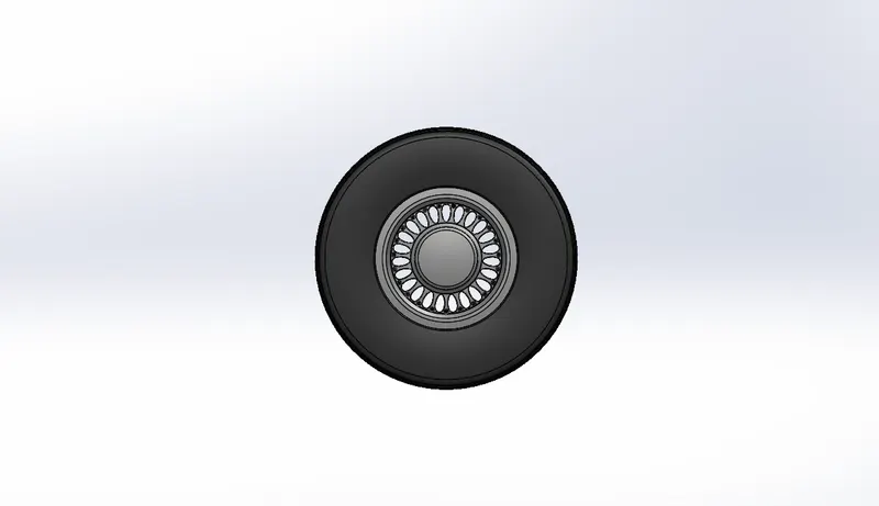
- In any type of airplane that has a tricycle type of landing gear, the wheel, tire and components in the front of the plane are referred to as nose gear.
Components:
Nose Gear:
View:
Isometric:
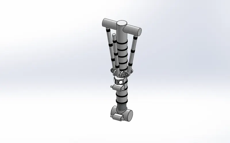
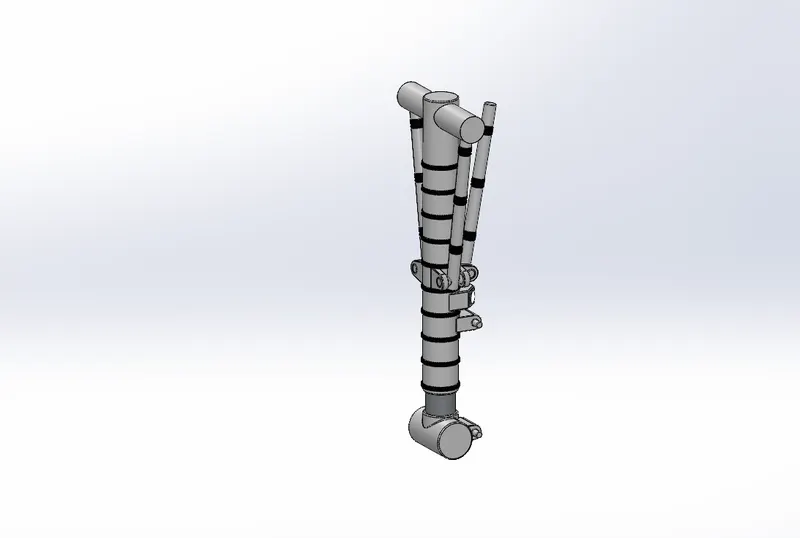
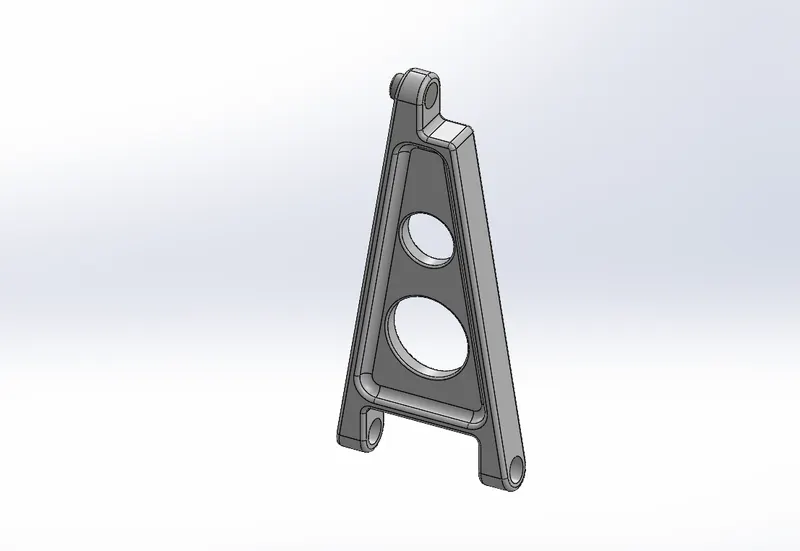
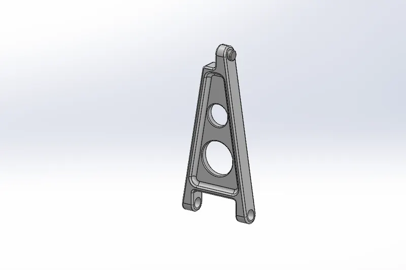
Nose Gear Suspention:
View:
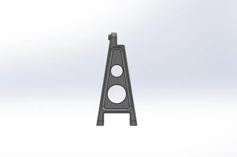
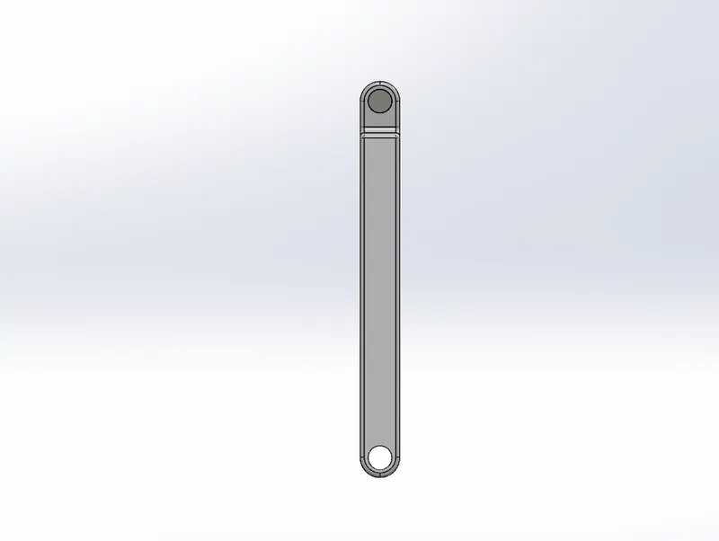
Isometric:
Tyre with Alloys:
Views:
Isometric:
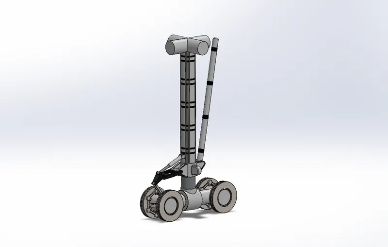
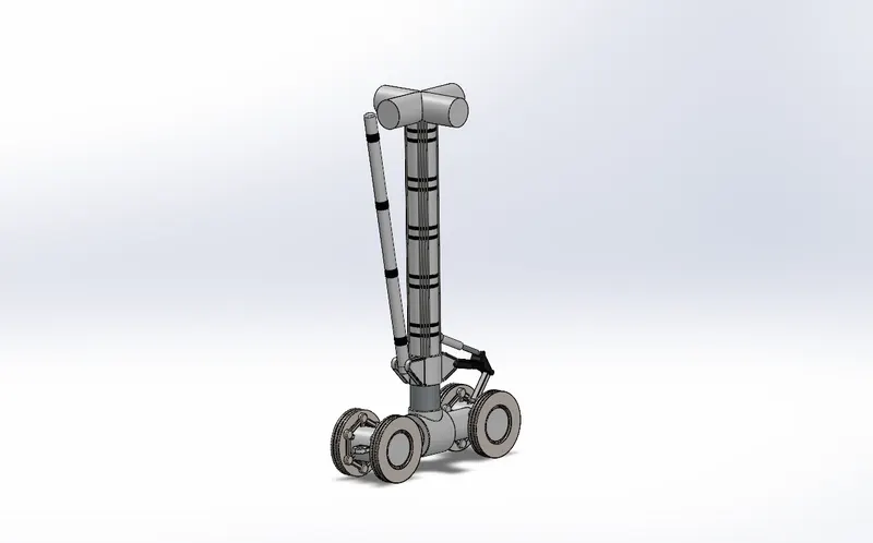
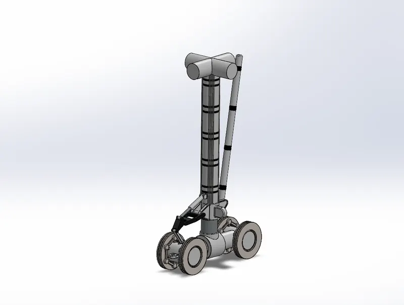
Main gear
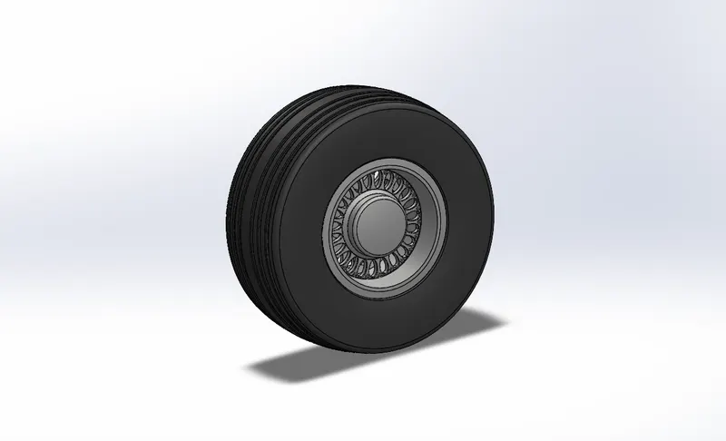
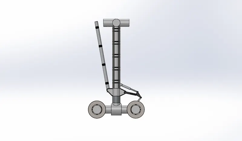
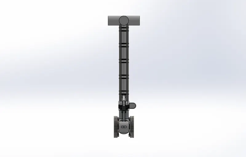
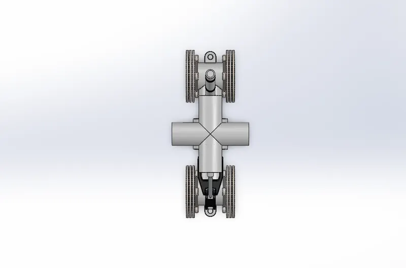
- Landing gear, the principal support of the airplane during landing, mainly consists of the shock absorber, wheel, brake system, turning system, undercarriage retractile system, etc.
- It is used to absorb the landing impact energy so as to minimize the loads transmitted to the airframe
Components:
Main Gear:
Views:
Isometric:
Tyre with Alloys:
Views:
Isometric:
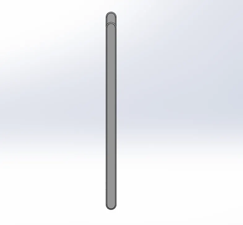
Main Gear Suspension :
Views:

Isometric:
Sub-Assemblies:
1.Nose Gear Assembly:
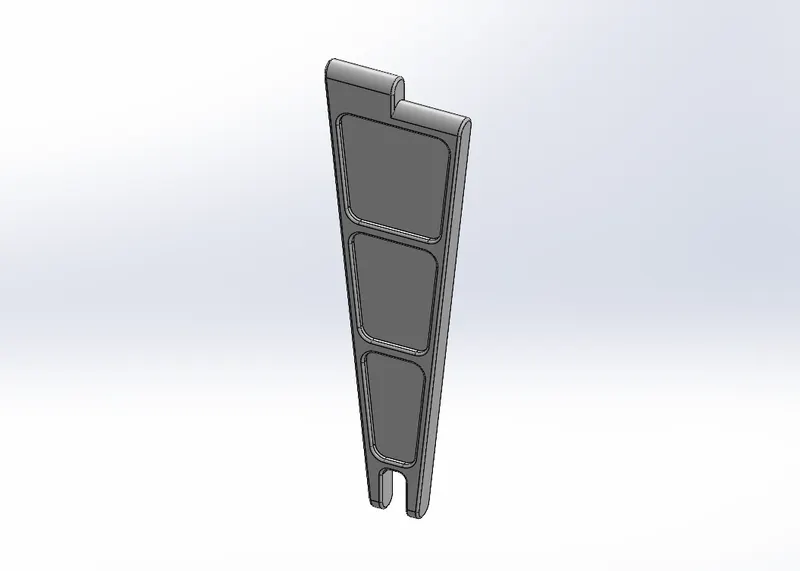
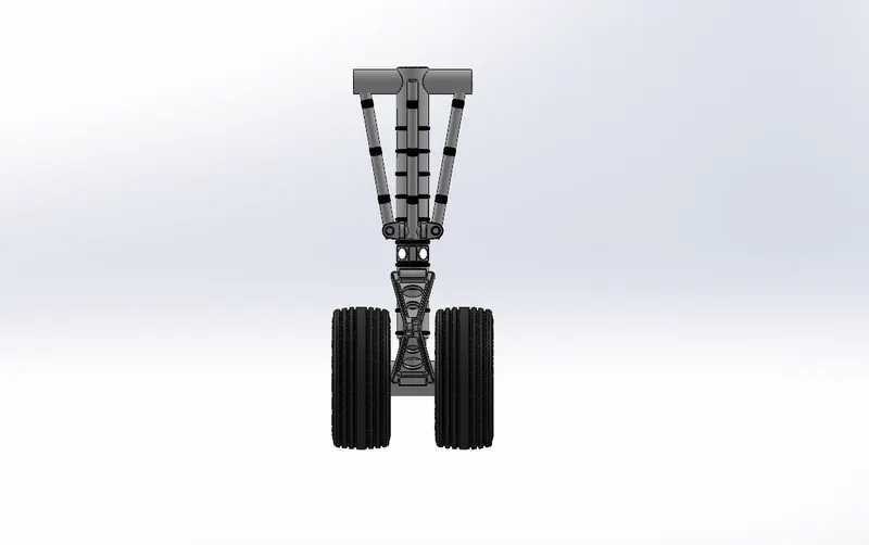
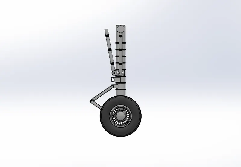
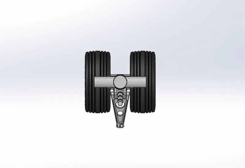
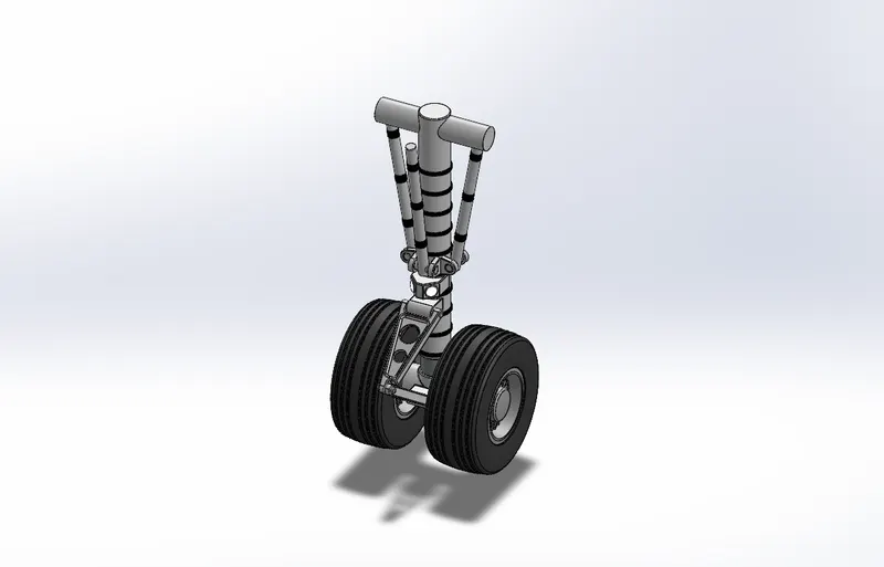
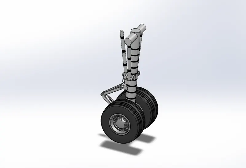
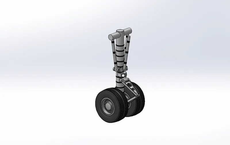
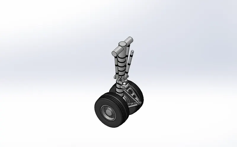
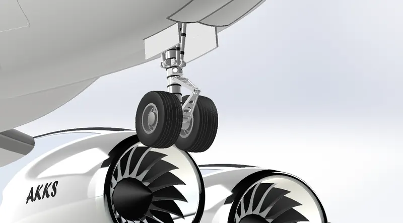
Nose gear has parts like Nose Gear base, Suspension Arms and Wheels. The parts are initially modelled and the parts are inserted into the assembly environment and the sub assembly is created for the Nose gear. In the Boeing 747-8 one Nose gear assembly is used. There are two wheels in the nose gear assembly.
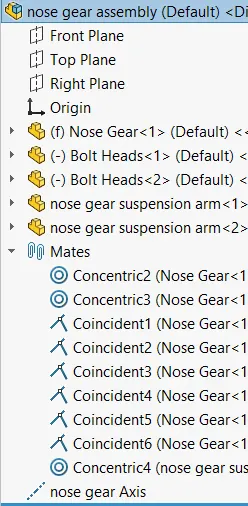
Mates:
Views:
Isometric:
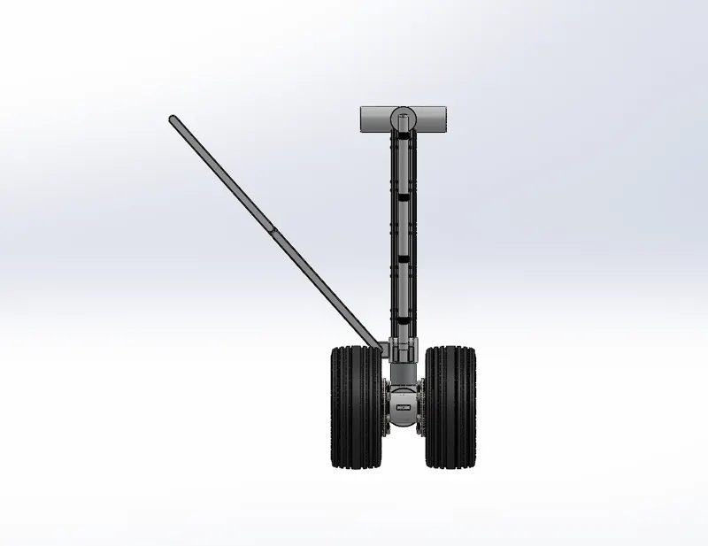
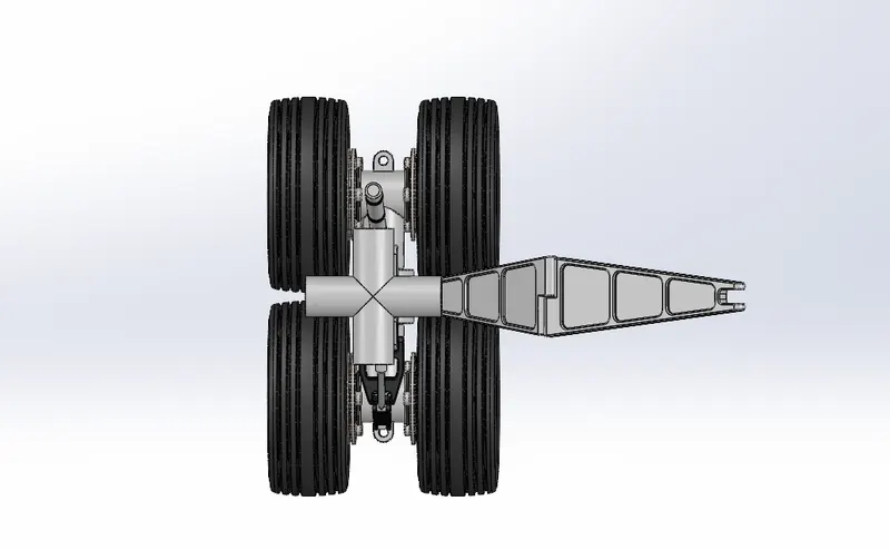
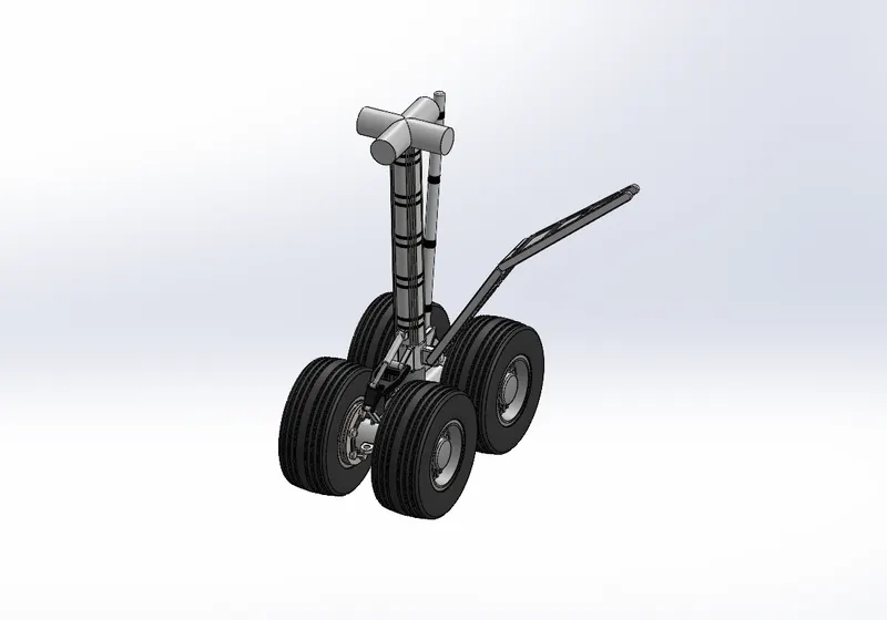
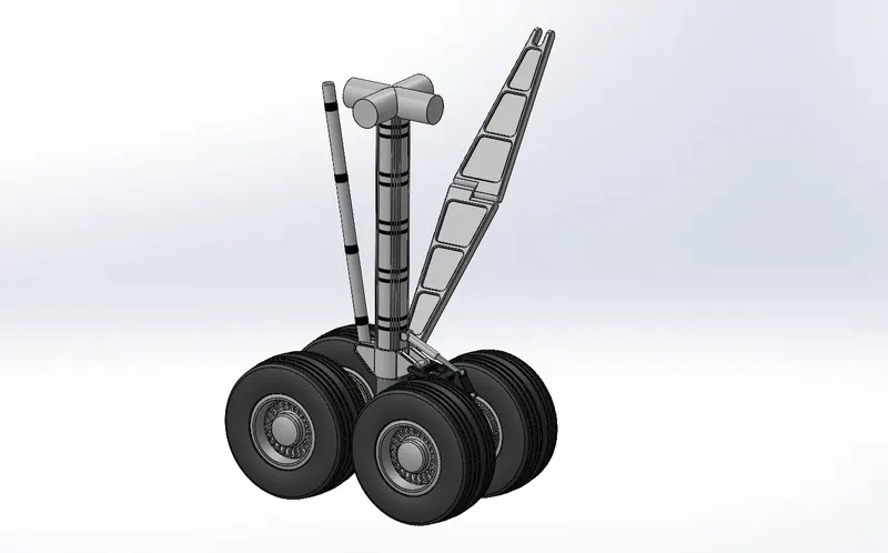
2.Main Gear Assembly:
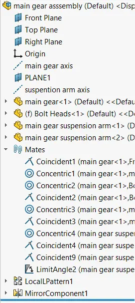
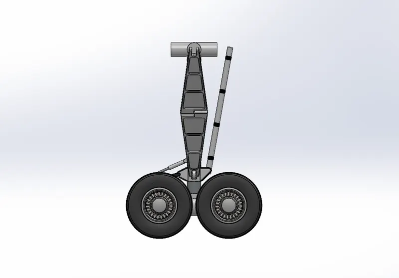
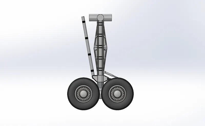
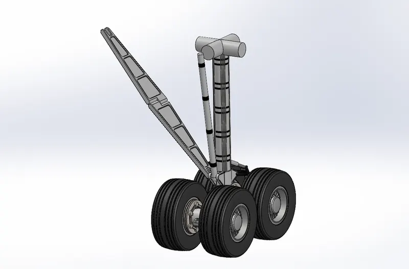
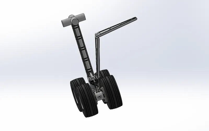
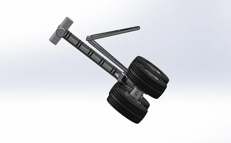
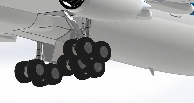
The Main Gear Assembly consists of the main gear base. two main gear suspension arms and four wheels
The parts for the main gear assembly are created initially then the parts are inserted into the assembly environment and Main Gear assembly is created.
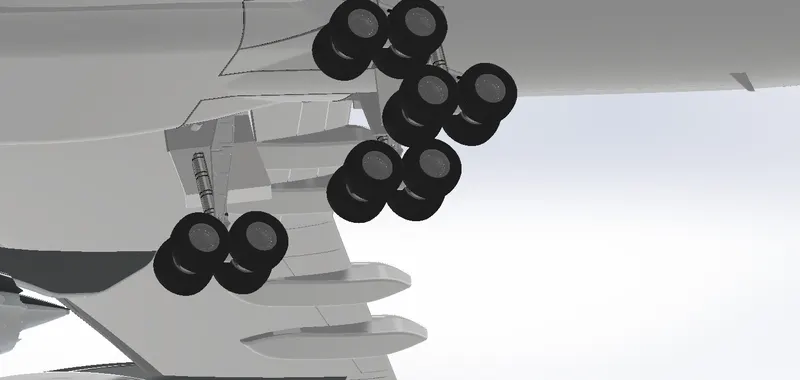
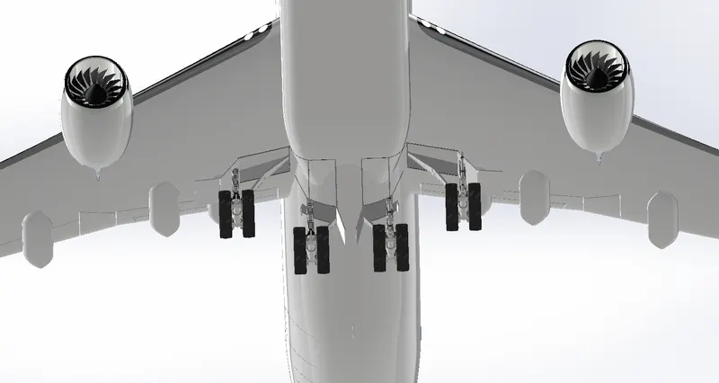
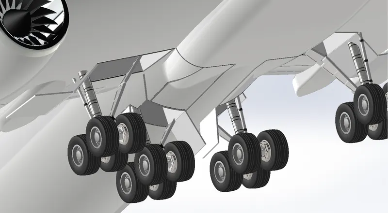
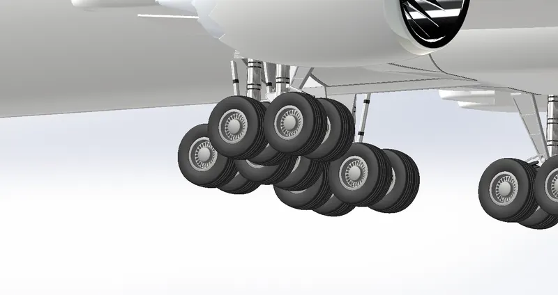
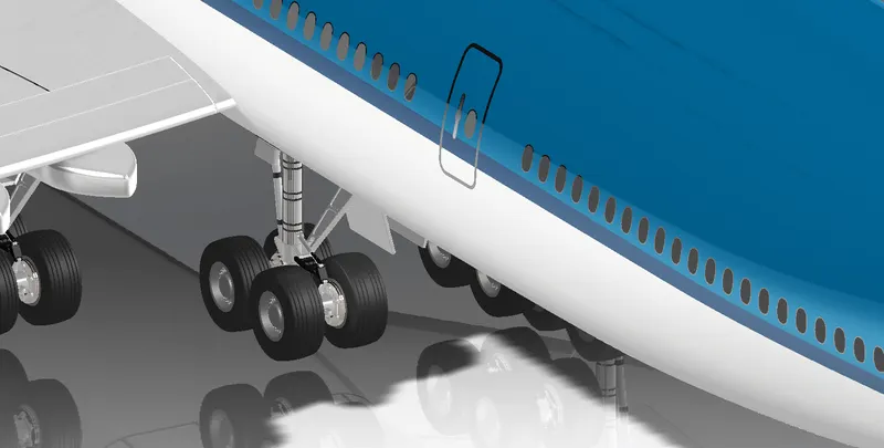
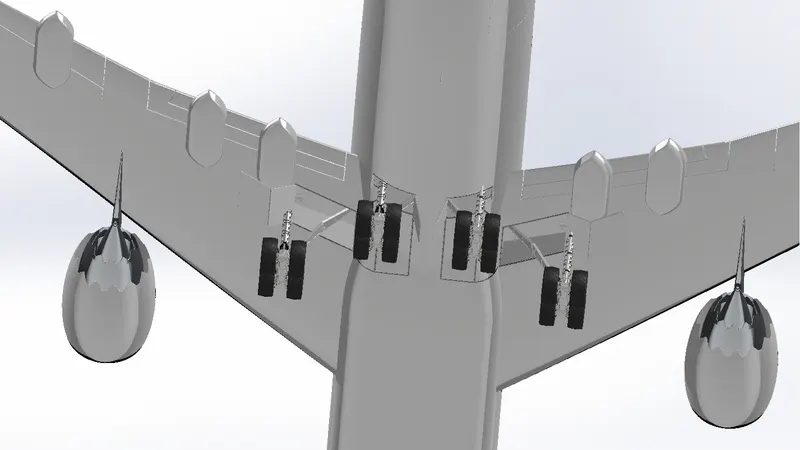
There are four main landing gears available in the Boeing 747-8. Each landing gear consists of four wheels. All the main landing gears are in the nearer to the rear side of the fuselage.
Mates:
Views:
Isometric:
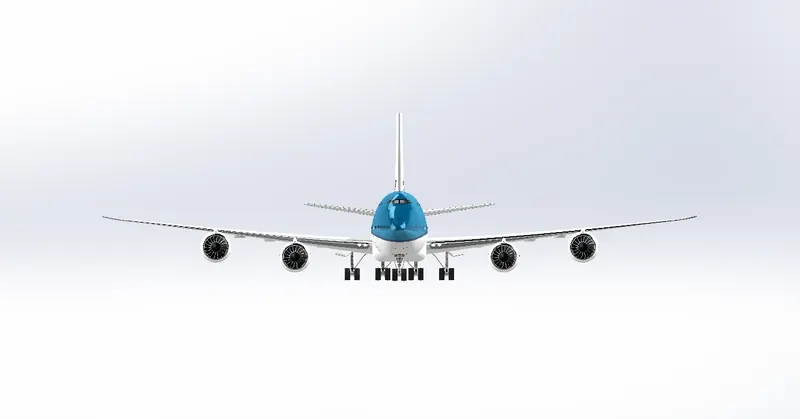
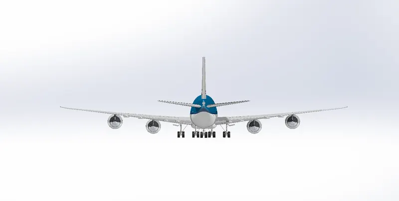
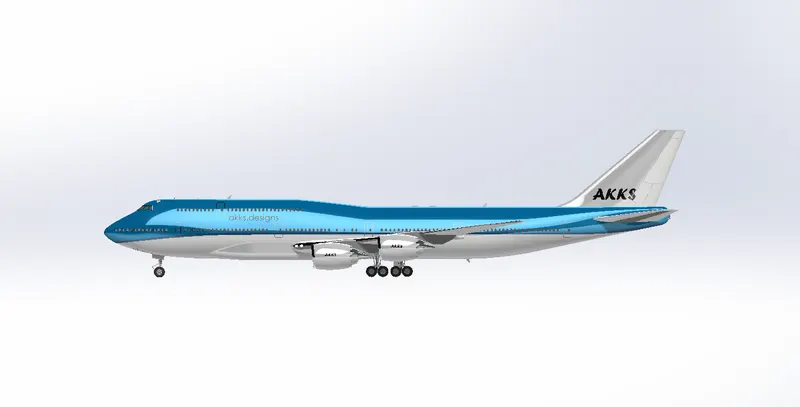
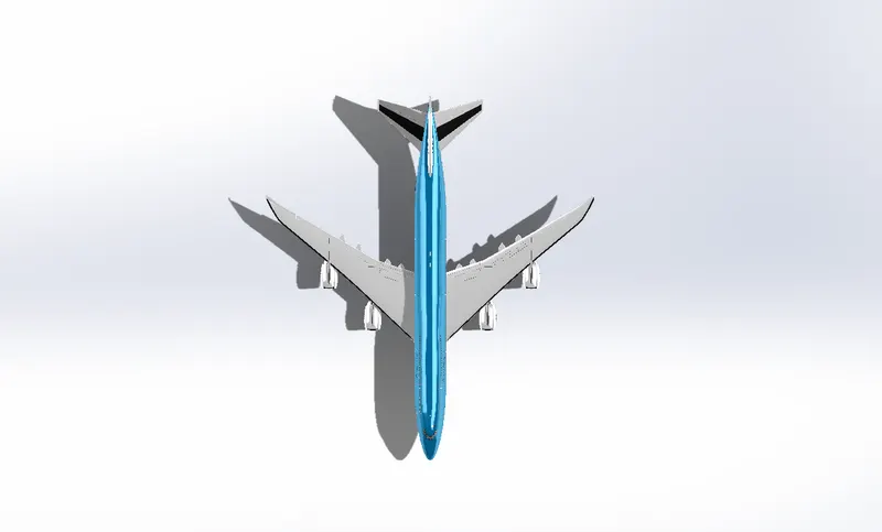
Boeing 747-8 Assembly:
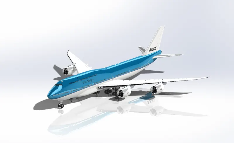
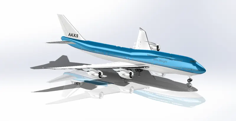
After completing the livery part the main body (Fuselage with all parts) are inserted into the assembly environment. Then the engine is inserted to the assembly.
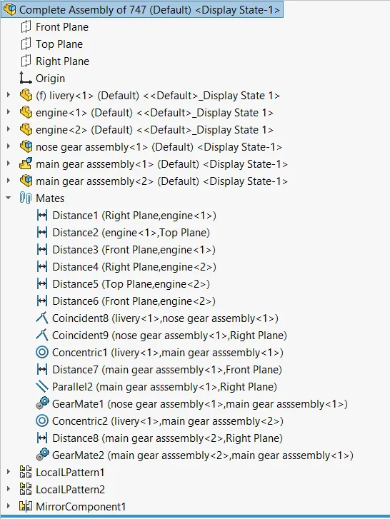
The engine is assembled with the main body by applying the coincidence and distance mates between the engine and fuselage planes Then by using the move/copy command other engines are created in the Assembly.
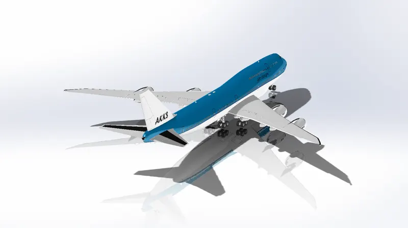
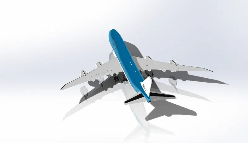
The same steps are followed for the Nose Gear and Main Gear assembly. The mate conditions are created between the Main, Nose Gear sub assembly and the Fuselage Finally the Boeing 747-8 is assembled.
There are different types of mates used in this project to assemble the parts together. The following are the mate conditions used in the assembly.
- Coincident mate
- Concentric mate
- Distance mate
- Angular mate
- Gear Mates.
Gear mates are one of the important mates and condition plays a major role in the movements of the landing gear. The gear mate is applied between the landing gears. If we move the Nose gear assembly the Main gear assembly also moves as same as the real one. The gear ratio is provided between the mates because of this ratio the gears will have moved in the proper manner.
Mates:
Views:
Isometric:
Details:
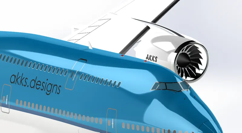
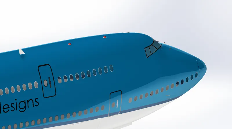
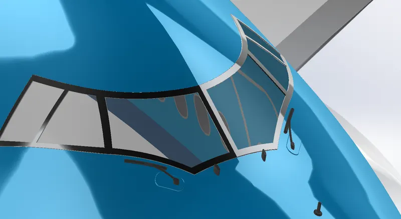
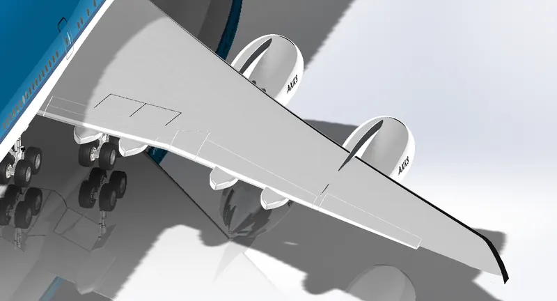
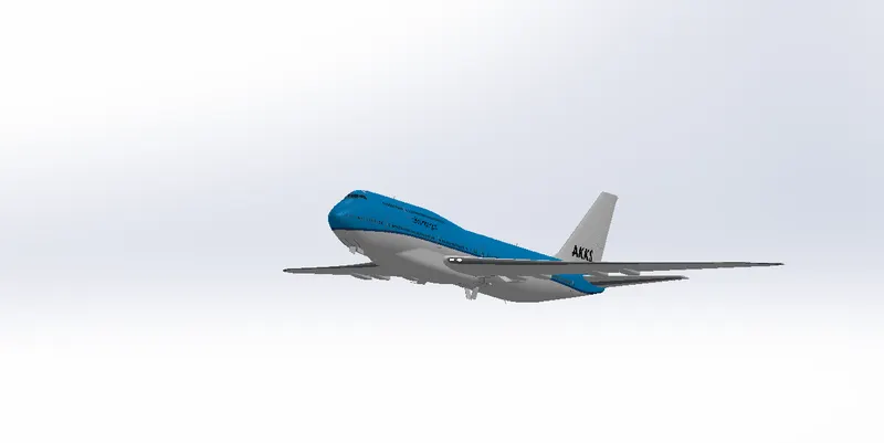
TAKE OFF:
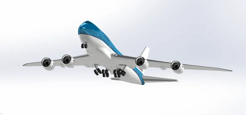
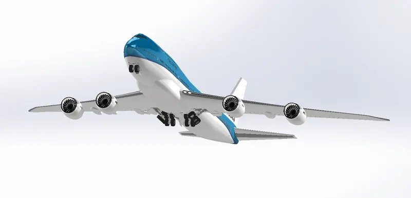
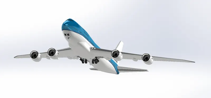
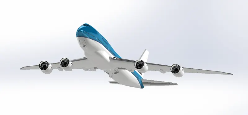
RENDERED
CONCLUSION
- The parts are sketched and modelled in the SOLDWORKS.
- The modeled parts are assembled with possible mates in to the main assembly
- The decals are applied to faces of parts.
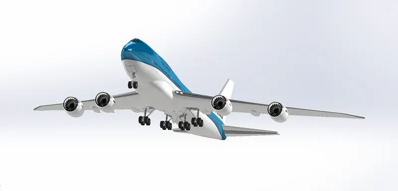
- The realistic image was rendered with the use of the Solidworks visualize.
REFERENCE
- skill-lync.com
FILE LINK:
https://drive.google.com/file/d/1ErOVHJdgDPiwTvjk0yAMg_2wq_Jvsc_1/view?usp=share_link
https://drive.google.com/file/d/18zaS-VYdSHKBNQU2ug8YZg3_JuTjKjVi/view?usp=share_link
https://drive.google.com/file/d/1ErOVHJdgDPiwTvjk0yAMg_2wq_Jvsc_1/view?usp=share_link