Photo Realistic Rendering
MODELING AND RENDERING OF AMERICAN CHOPPER
OBJECTIVE
- To create parts of chopper using Solidworks.
- To Assemble all the parts of chopper.
- To know the application of decals,lights and camera etc.
- To create photorealistic model and rendering photoview 360 and solidwork visualize.
INTRODUCTION
SolidWorks is a solid modeling computer-aided design (CAD) and computer-aided engineering (CAE) application published by Dassault Systèmes. It has other ADD-in features like photoview360 which helps in rendering modelS to make it look photo realistic. In this project we learnt about detailed design of Americal chopper parts and assemblig them and rendering the final after assembly.
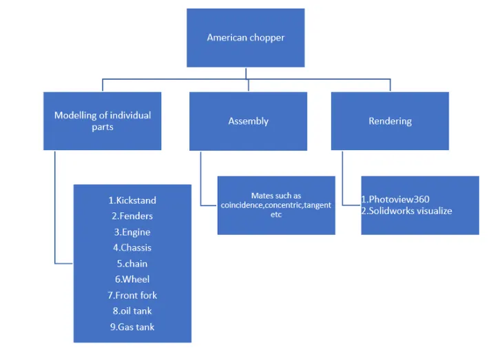
DESIGN METHODOLOGY
- Part Modeling
- Part Assembly
- Rendering
SOLIDWORKS TOOLS AND FEATURES USED TO MODEL AMERICAN CHOPPER
Fixing SKETCH for start any modeling:
2D TOOLS include in sketch are
- Line
- Circle
- Arc
- Spline
- Rectangle
- Circular Pattern
- Polygon
- Offset
- Fillet
- Mirror
- Ellipse
- Chamfer
- etc
(Each tool have their own unique uses also have contained more options)
Then using FEATURES we can change 2D sketch to any required 3D model objects and any desired item
- Blocks: We can save, edit and insert blocks from the drawing items and sketch entities that you use often such as standard notes, title blocks, label positions and so on you can attach blocks to geometry or to drawing views.
- Boss Extrude: Feature used for expand the object in 3D according to sketch plane.
- Revolve boss base: Feature is used to make cylindrical or circular 3D extrude along with a given reference axis as per drawn sketch.
- Extrude Cut: Extrude cut feature used to cut/remove the 3d object in linear path according to sketch.
- Revolve cut: Revolve cut is used to cut or reduce the extrude of cylindrical round surface.
- Lofted Boss/Base: Lofted boss is a feature used to achieve Complex Shapes. It does this by interpolating surfaces between various cross-sections of a model. These cross-sections can be sketches, faces, or edges.
- Sweep: This feature is used to sweep any kind of fully defined sketch along with the path.
- Sweep cut: Sweep cut is same as sweep feature but its directly proportional to sweep which makes a cut along with the sweep path.
- Linear Pattern: The linear parent is used to create a different number of instances required to create the pattern linearly.
- Circular pattern: Circular pattern is a feature used to make 3d feature into circular pattern according to number of insistences.
- Swept Surface: It is used to make a surface along with a path the curve is driven.
- Boundary Surface: Boundary surface is used to make a surface in between two finished surfaces.
- Curve Driven Pattern: Curve driven pattern is used to make any pattern which followed by the curve is sketched before.
- Curve Driven Pattern: Curve driven pattern is used to make any pattern which followed by the curve is sketched before.
- Loft Surface: Loft surface is used to make loft in between two profiles along with guide path.
- Knit surface: Knit surface is used to knit the two free edges or open edges of the surfaces together also it reduces the gap between the two edges of the surface.
- Move/copy body: This feature is used to move/copy the 3D body to one place to another place.
- Surface Trim: Primarily used to cut away material from a surface, and provides two modes: Standard and Mutual.
- Mirror: Mirror is used to mirror a feature or body by reference of the selected plane.
- Fillet: Fillet is a feature used for making round internal or external edges to avoid sharp edges and make it smooth.
- Chamfer: Chamfer is used to make a sharp edge or corner slightly tapered rather than being a perfect square.
- Split: Split tool is used to split single solid part into two solid parts. It is used to project an entity onto other surfaces or curved/planar faces.
- Dome: Dome is a feature used to make dome shaped extrude including elliptical dome.
- Shell: Shell feature is used to make to hollow space in solid part by selecting outer wall of the solid part and so removes the inner parts. It is also used to reduce the specific thickness.
- Combine: Combine tool is used to make integration of two solid parts which intersect each other as same solid part.
- Projection Curve: Projection curve is a 3D curve which is projected on the basis of the two different 2D curves in two different planes.
- Trim entities: it is used to trim the unwanted lines or extended entities in the sketch.
- Appearances: An appearance defines visual properties of the model including colour and texture. Appearances do not affect physical properties which are defined by materials. every material is a assigned a default appearance.
AMERICAN CHOPPER INDIVIDUAL PARTS:
- CHASSIS
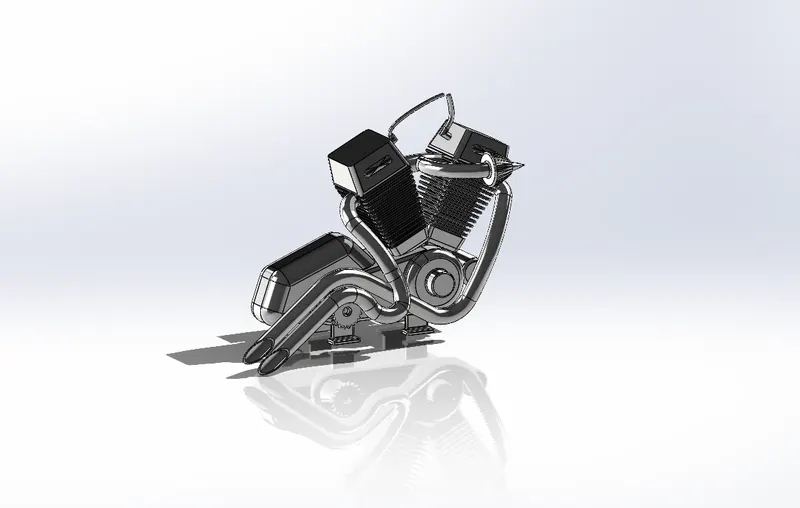
- ENGINE
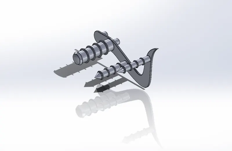
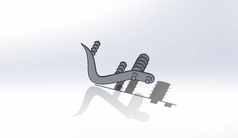
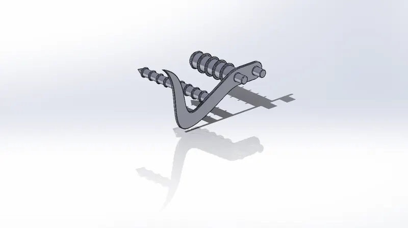
- PEDAL
- KICKSTAND
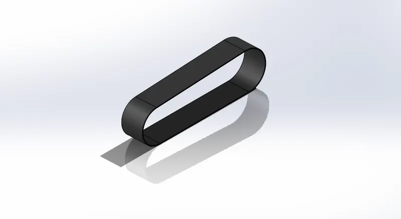
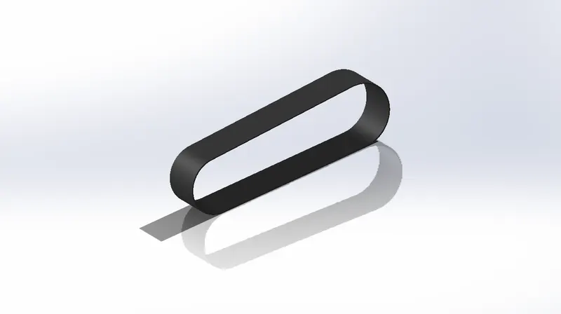
- TRANSMISSION BELT
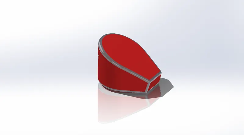
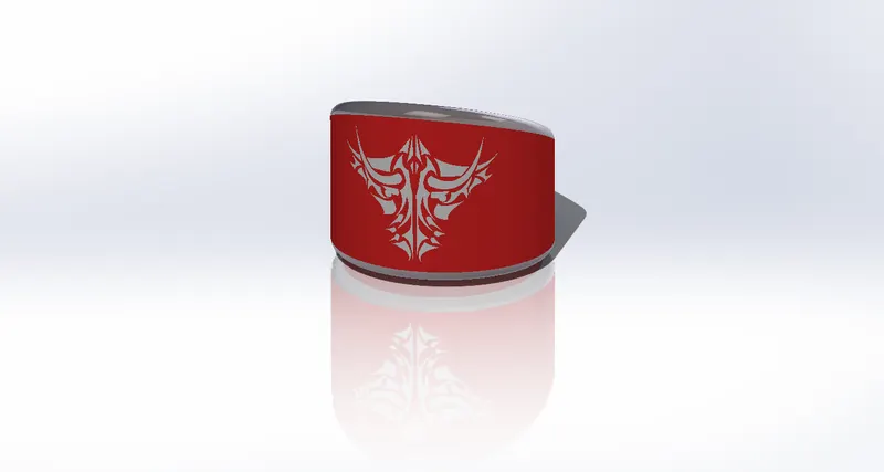
- OIL TANK
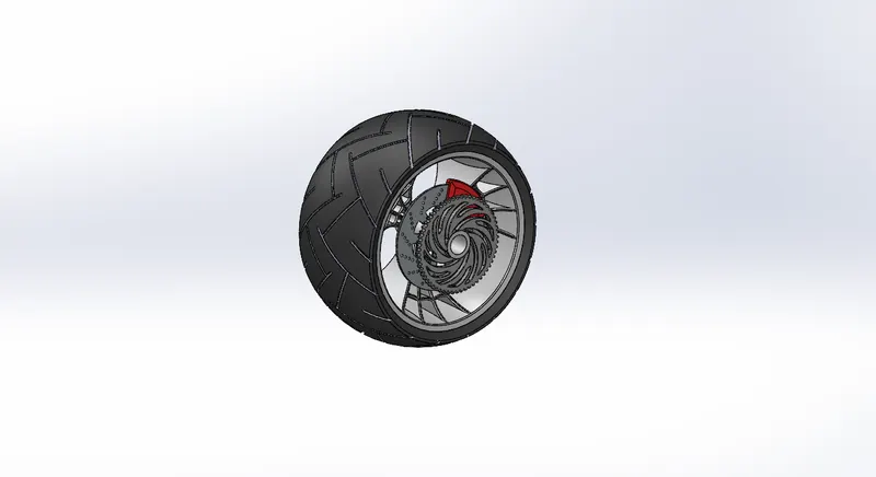
- REAR WHEEL
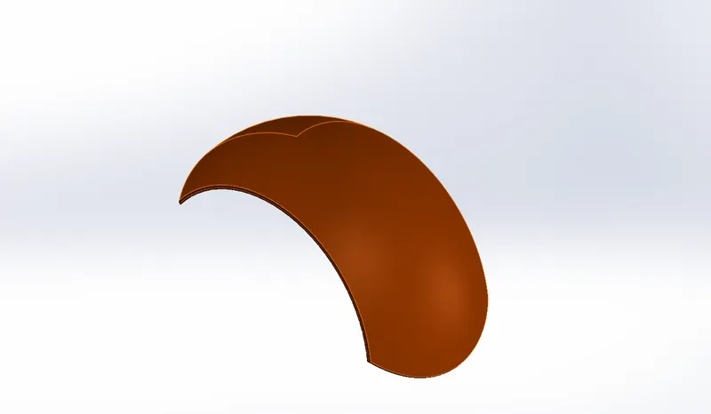
- REAR FENDER
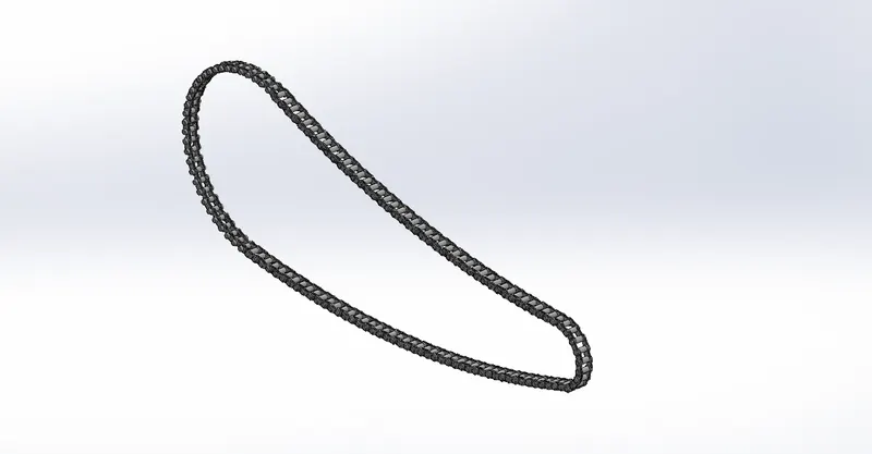
- CHAIN
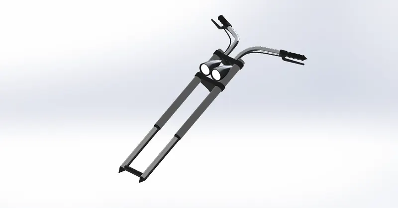
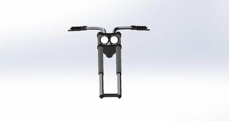
- FORK
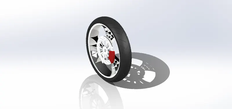
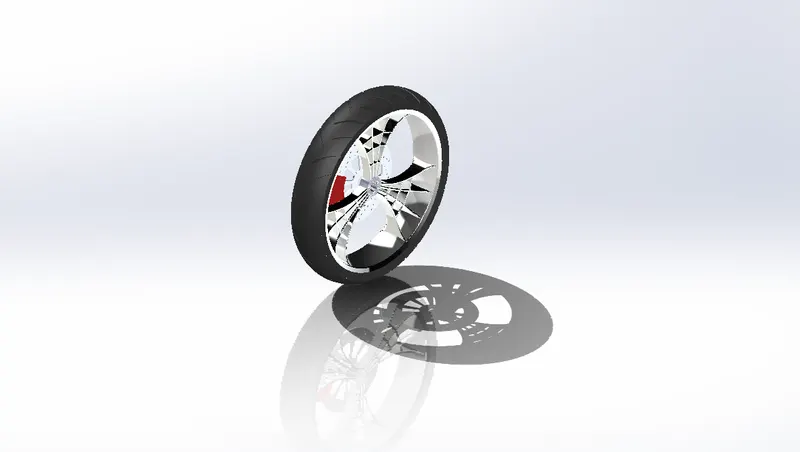
- FRONT WHEEL
- FRONT FENDER
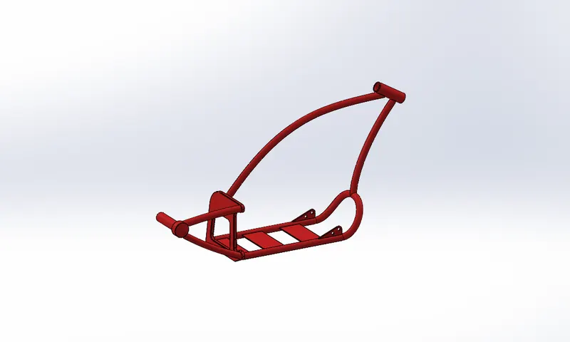
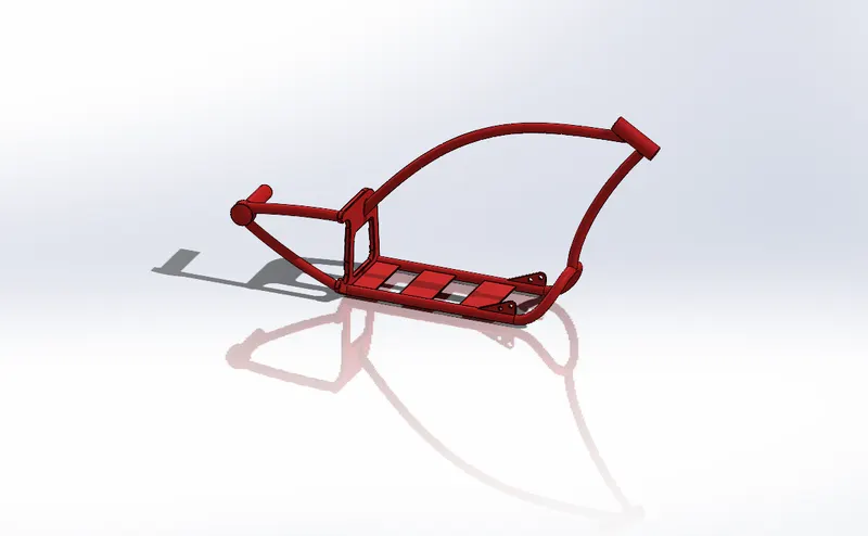
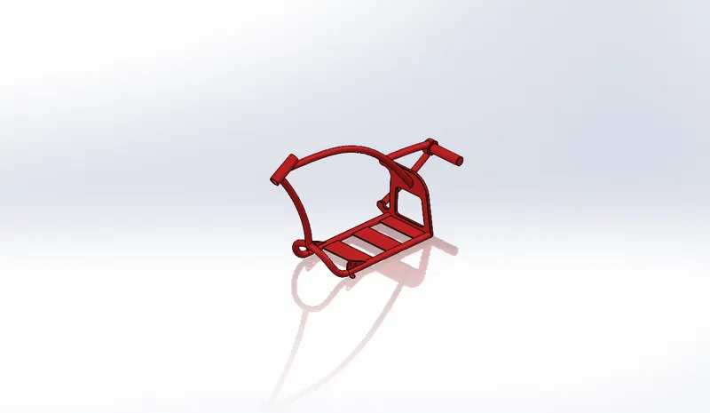
chassis:
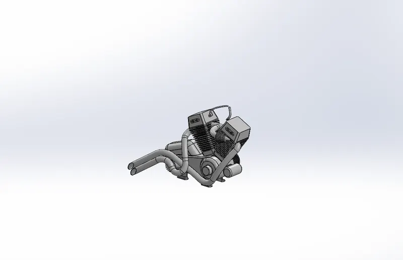
Engine:
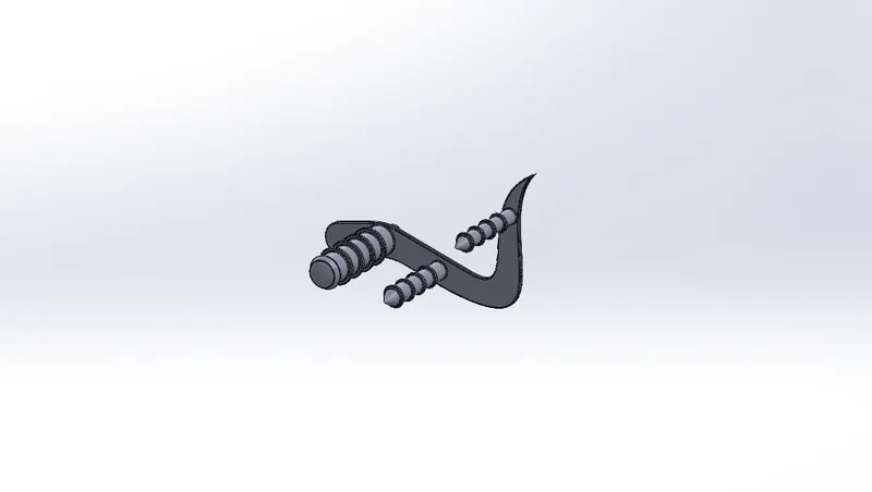
Pedal:
Kickstand:
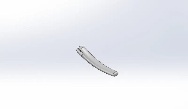
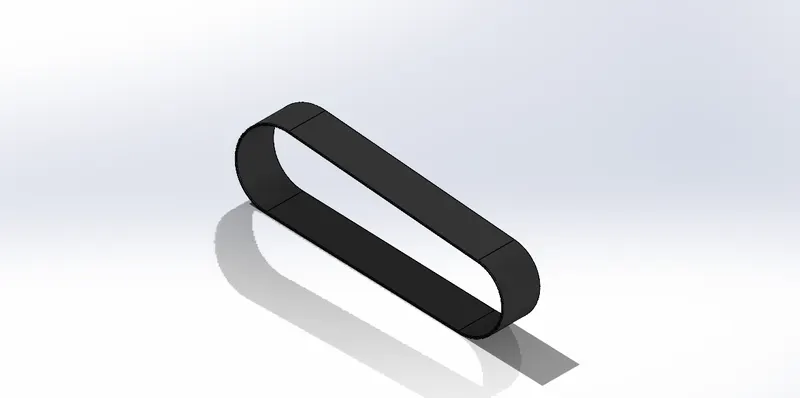
Transmission Belt
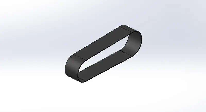
Oil Tank
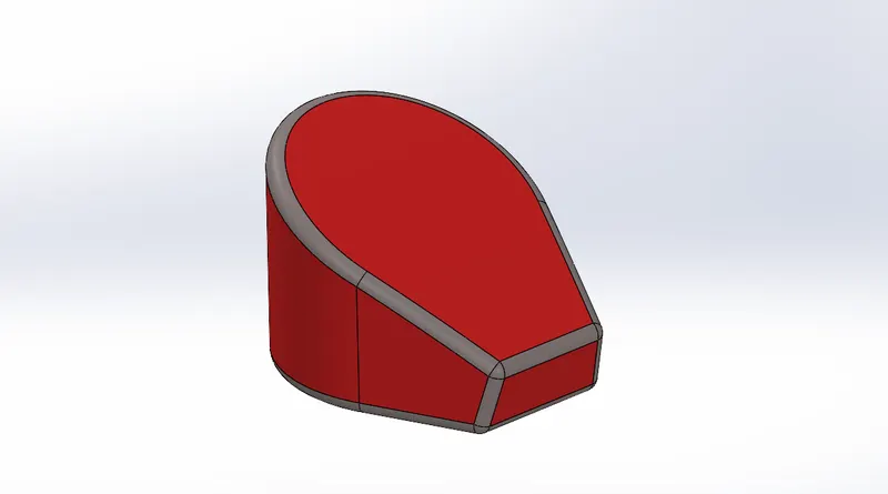
Rear Wheel:
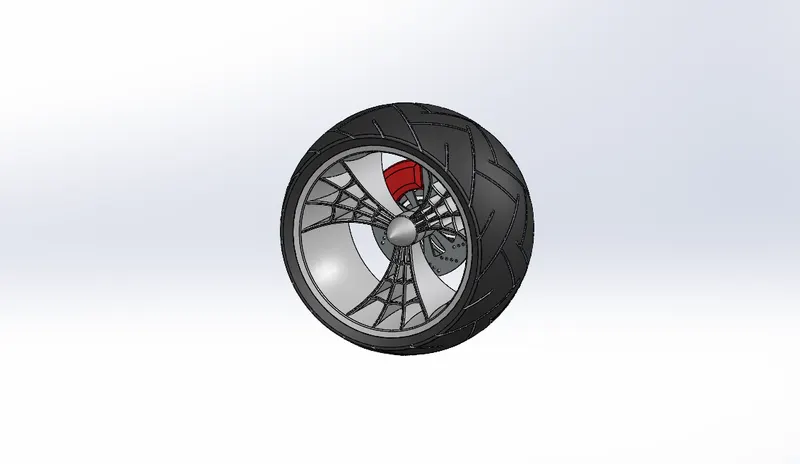
Rear Fender:
Chain:
Gas Tank:
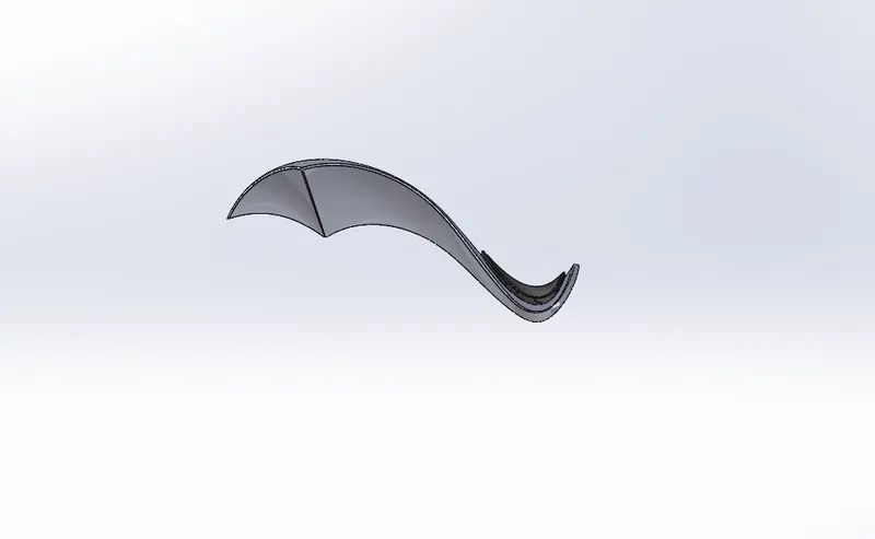
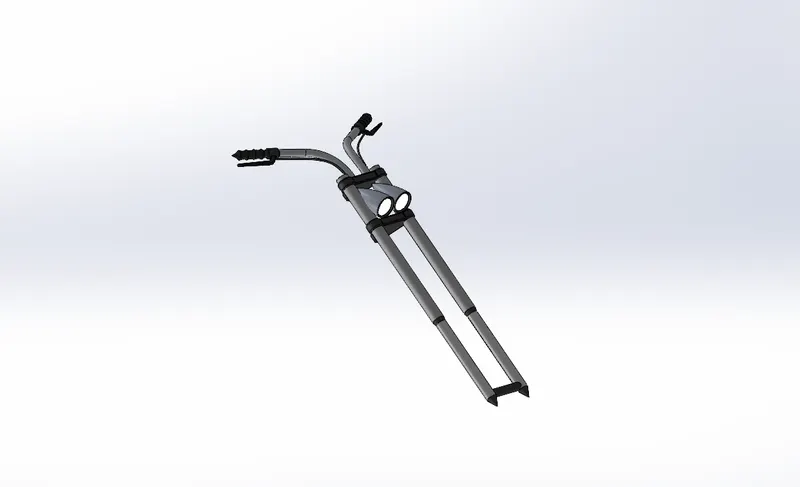
Fork:
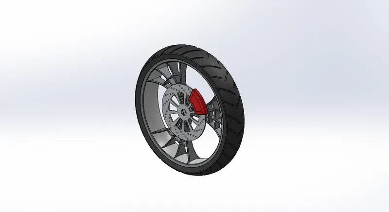
Front wheel:
Front Fender:

Chopper Parts with Appearance:
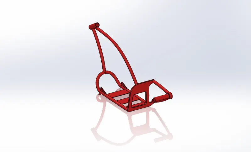
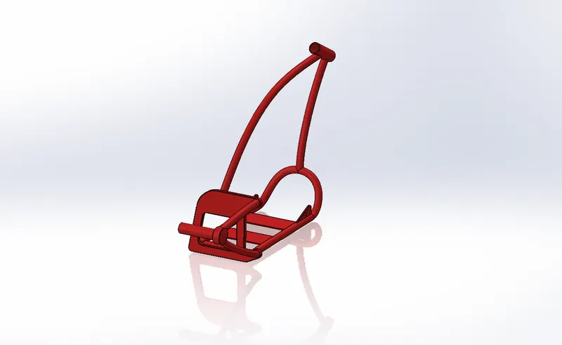
CHASSIS:
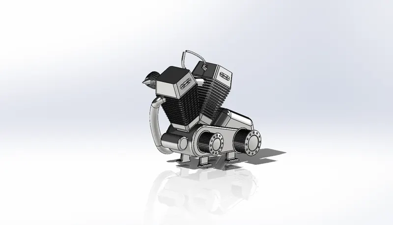
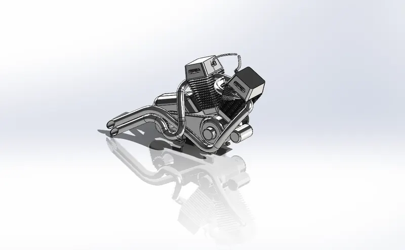
ENGINE:
PEDAL:
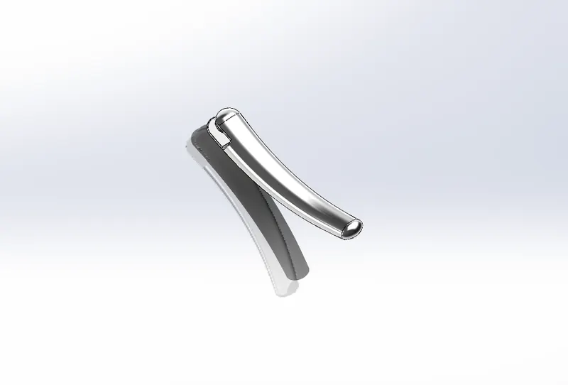
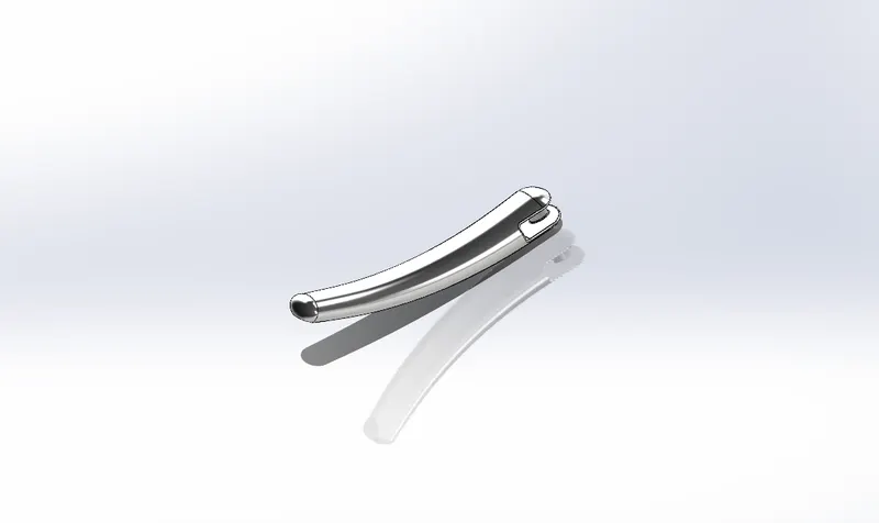
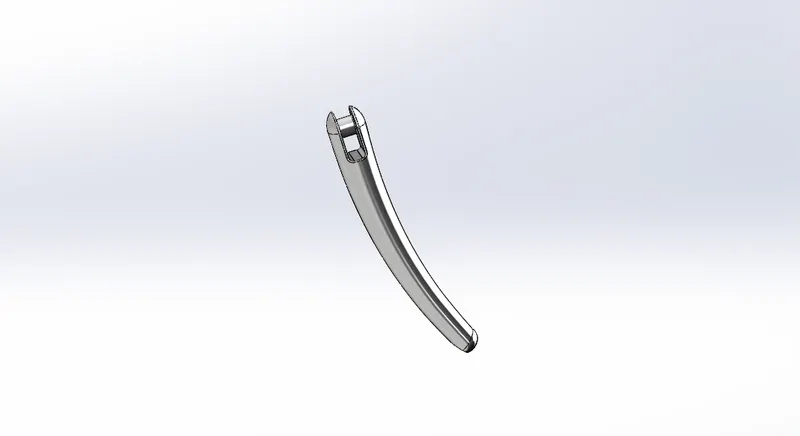
KICKSTAND:
TRANSMISSION BELT:
OIL TANK:
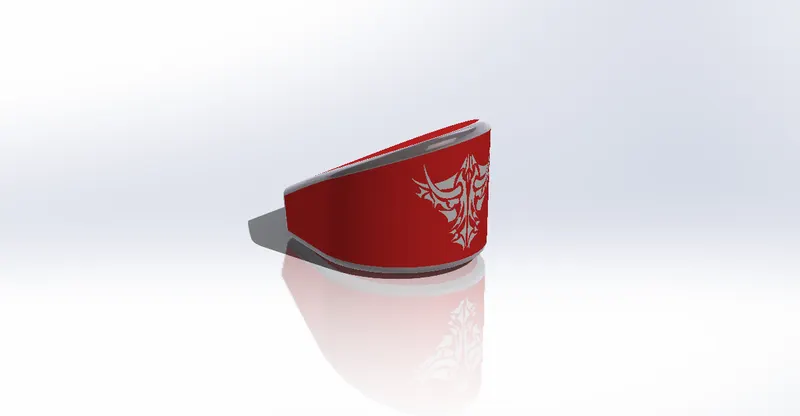
REAR WHEEL:
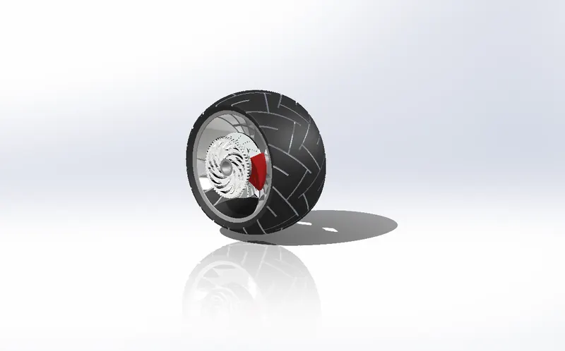
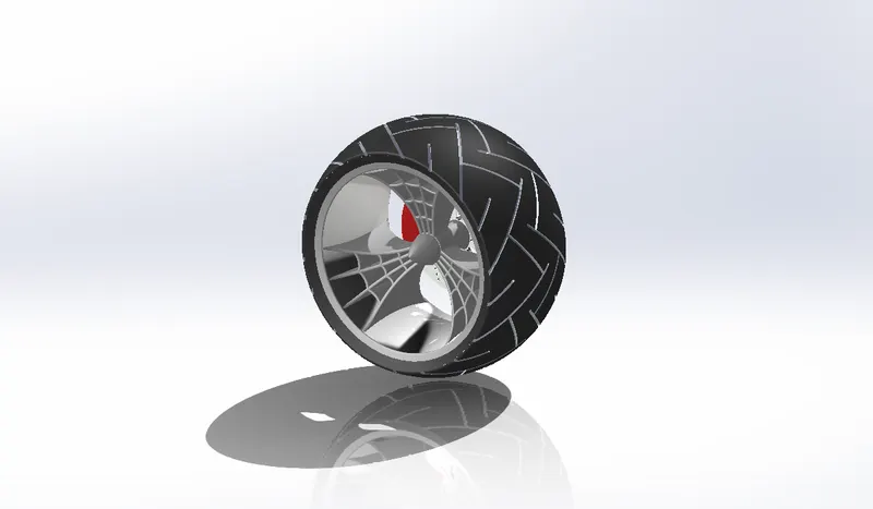
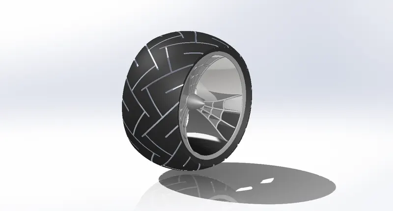
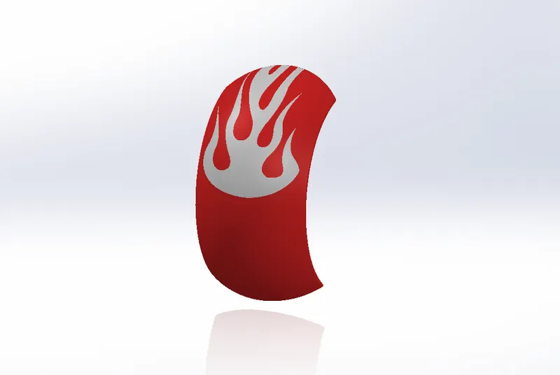
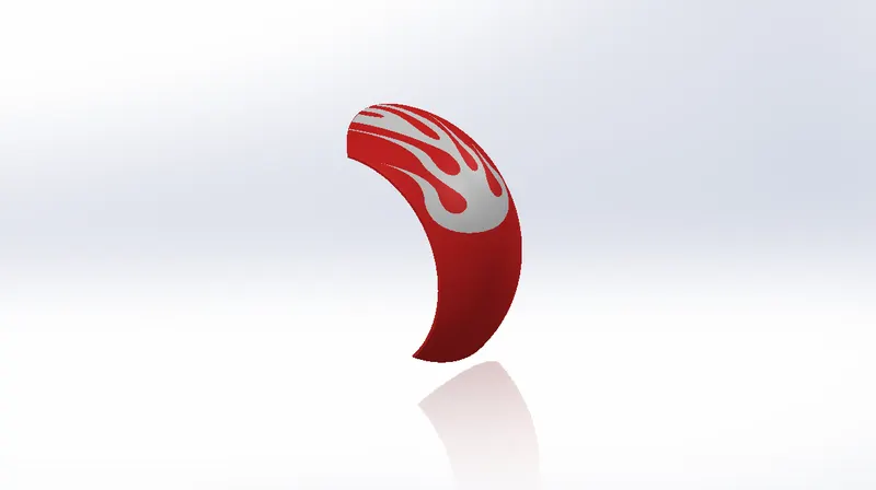
REAR FENDER:
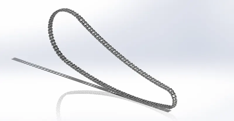
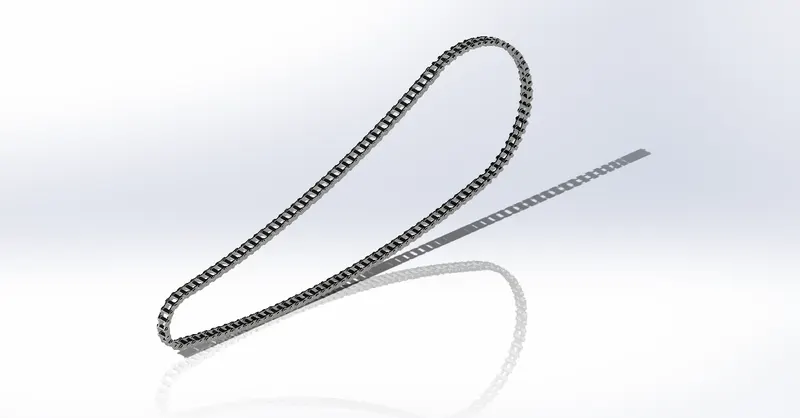
CHAIN:
GAS TANK:
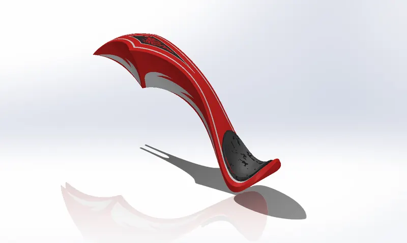
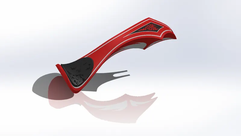
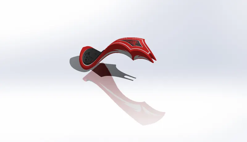
FORK:
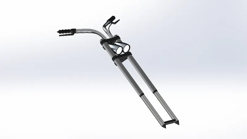
FRONT WHEEL:
FRONT FENDER:


ASSEMBLY
- create assemblies using bottom-up design,
- top-down design, or a combination of both methods.
To create a drawing from within a part or assembly document:
- Click Make Drawing from Part/Assembly. (Standard toolbar or New. flyout menu).
- Select options for Sheet Format/Size, then click OK.
- Drag views from the View Palette into the drawing sheet, and set options in the PropertyManager.
A general rule to follow is that one part (multibody or not) should represent one part number in a Bill of Materials. A multibody part consists of multiple solid bodies that are not dynamic. If you need to represent dynamic motion among bodies, use an assembly.
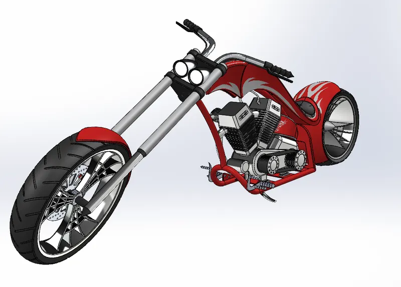
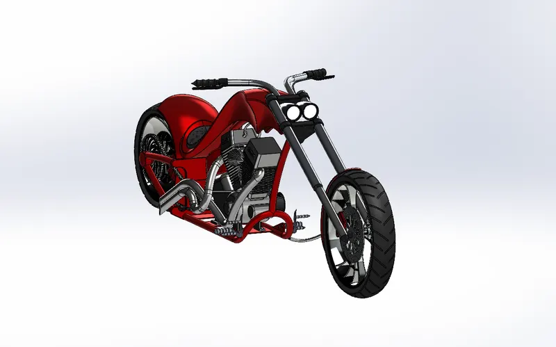
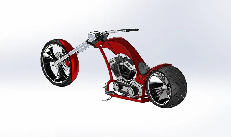
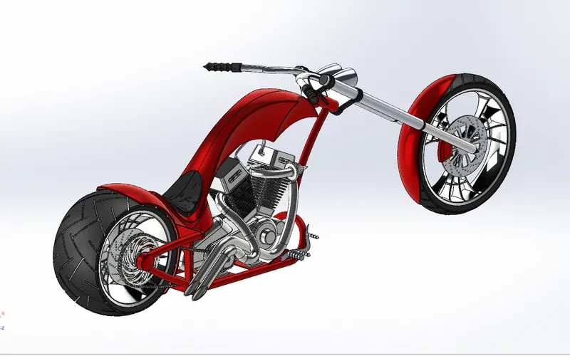
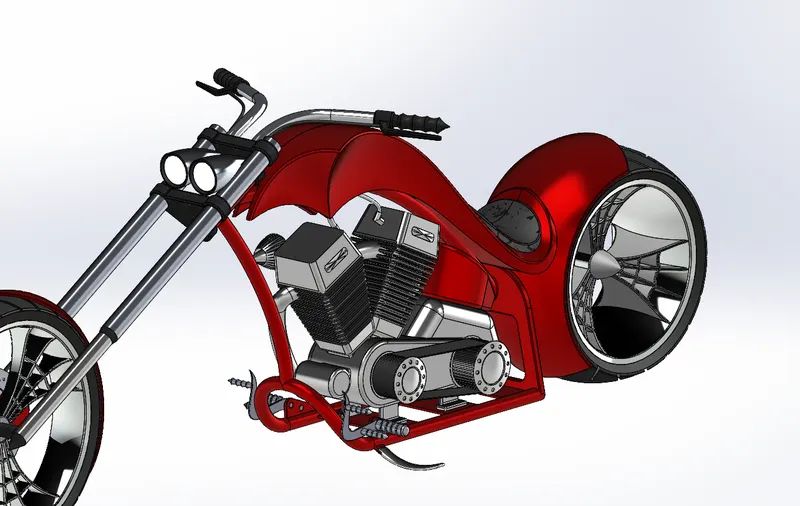
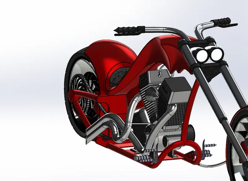
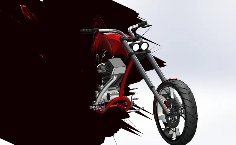
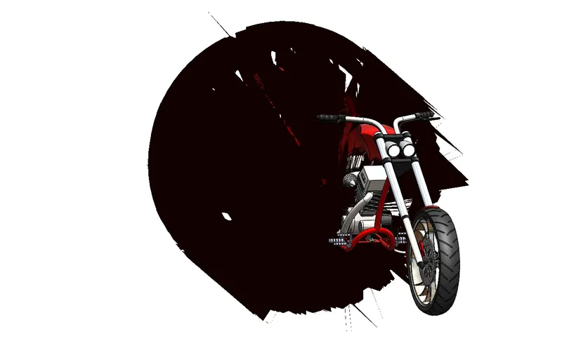
RENDERING
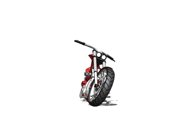
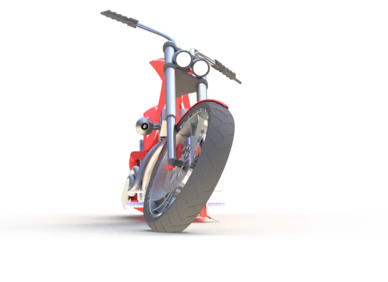
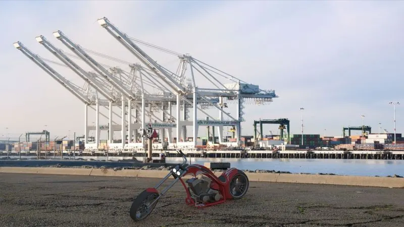
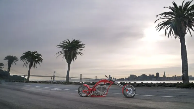
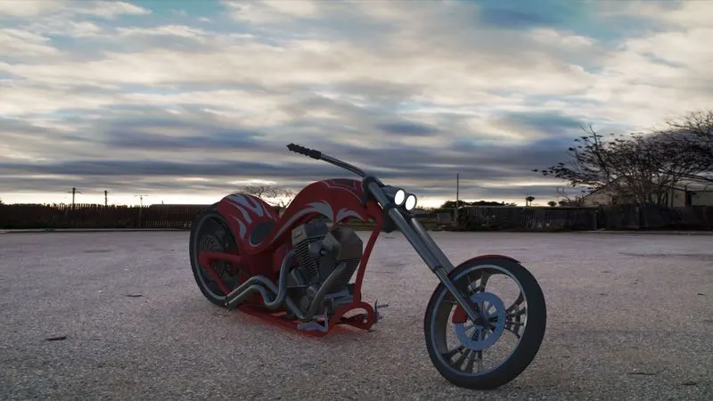
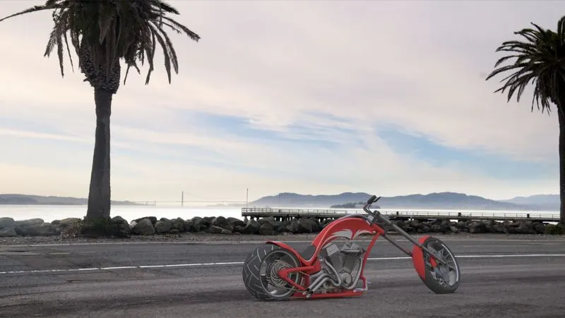
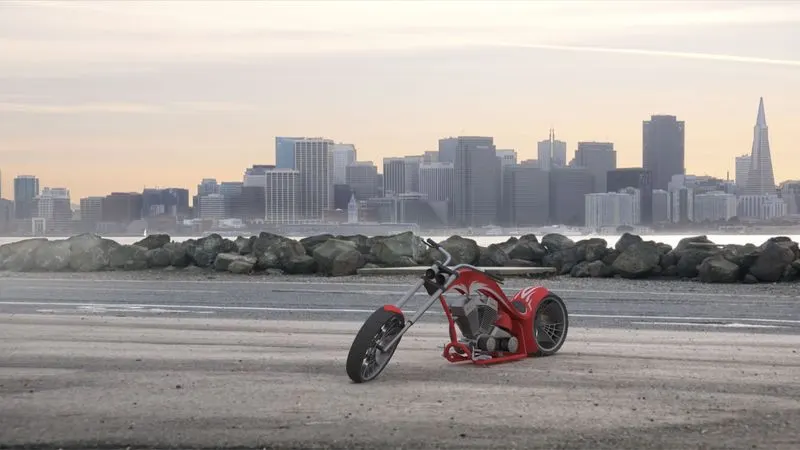
SOLIDWORKS Visualize is a photo-realistic rendering tool that utilizes your CAD data to create magazine quality images or commercial quality animations.
Rendering refers to the process of applying a coat of cement on the external walls of a property to make them smooth or textured as desired. The difference between rendering and plastering is that rendering involves the exterior walls while plastering involves the interior ones.
In 3-D graphic design, rendering is the process of add shading, color and lamination to a 2-D or 3-D wireframe in order to create life-like images on a screen. Rendering may be done ahead of time (pre-rendering) or it can be done in on-the-fly in real time.

CONCLUSION
- The parts are sketched and modelled in the SOLDWORKS.
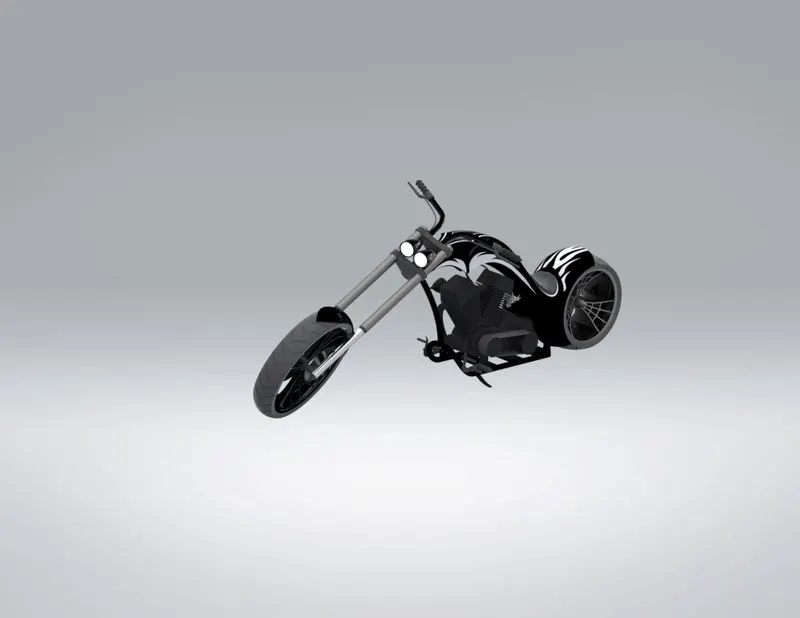
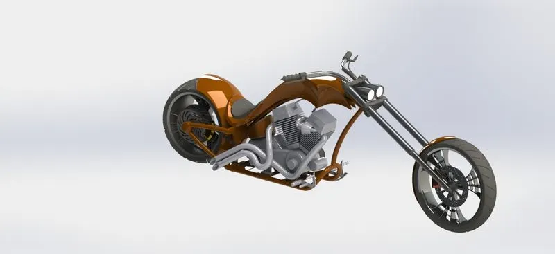
- The modeled parts are assembled with possible mates in to the main assembly of American chopper.
- The decals are applied to faces of parts.
- The realistic image was rendered with the use of the Solidworks visualize.
REFERENCE
- skill-lync.com/student-projects
- help.solidworks.com
- www.techtarget.com