Radar Mast & Final Assembly of Yacht
Detailed report on the design and modelling of the Sunseeker Predator 108 luxury Yatch and Final Assembly of Yacht
Report Created By- Rishabh Soni
Introduction:-
Sunseeker Predator 108:-Sunseeker Predator 108 is a 32.92 m / 108′1″ luxury motor yacht. She was built by Sunseeker in 2007. With a beam of 6.3 m and a draft of 1.58 m, she has a fiberglass hull. She is powered by MTU engines of 2000 hp each giving her a maximum speed of 45 knots and a cruising speed of 35 knots. The motor yacht can accommodate guests in 4 cabins with an interior design by Sunseeker
Some Yatch Specifications:-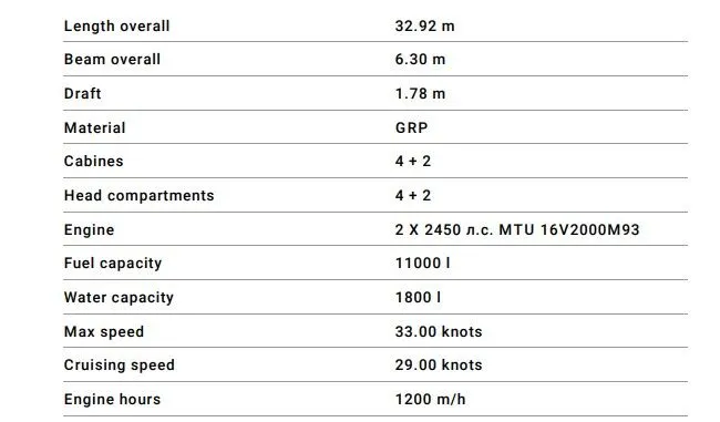
Objective:- Design all the individual parts of yacht with suitable solidworks features. Assemble the individual parts by using standard mates in assembly environment. Render the assembly model by assigning the appearance features like decals, scenes and camera. Learn the different techniques of surfacing in the solidworks.
Design Methodology:-The methodology which is used in the design and rendering of this yatch is shown in with the help of the flow chart diagram
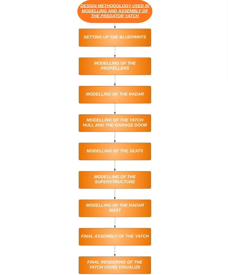
DESIGN FEATURES USED WHILE MODELLING:-
BOSS EXTRUDE:- It is a basic tool in Solidworks which converts a 2D sketch in to a 3D model with respect to its geometry in normal direction. First, we have to draw a fully closed 2D sketch and then extrude it by defining its starting point, ending point, contours and direction of extrusion.An extrude operation can either add material to a part or remove material from a part.
SWEEP:- A sweep tool is used to sweep a closed 2D sketch along an open or closed path. This tool is generally used for making tubes and bars. A closed loop and a path to sweep are required.
REVOLVE:- The revolve feature is used to revolve a 2D sketch along an axis or centreline and makes it a 3D model. A 2D sketch is drawn and revolved by selecting a line as a reference for axis of rotation and defining the angle of rotation.
KNIT SURFACE:- It is used to combine 2 or more faces and surfaces into one.
MIRROR:- Mirror tool in solidworks is used to copy a 2D or 3D object about a reference line or plane. We can have either only the mirrored object or both the original and mirrored objects.
SURFACE LOFT:- Loft Surfaces are surfaces generated by multiple 3D Curves or existing edges creating a smooth tangency between the selected curves. Match Points are created between each selection denoting the orientation and path of the loft surface.
SURFACE EXTRUDE:- Surface Extrude feature, we can extrude the boundary edges of a face of a solid body or edges of a surface body in a customized direction. When we run the Extruded Surface command, two things can happen: Either a sketch is active or preselected or no sketches exists.
PROJECTED CURVES:- A projected curve is a 3D curve that represents the intersection of two extruded surfaces of two sketches on intersecting planes.
SHELL:- The shell tool hollows out a part, leaves open the faces you select, and creates thin-walled features on the remaining faces. If you do not select any face on the model, you can shell a solid part, creating a closed, hollow model. You can also shell a model using multiple thicknesses. The thickness of the shell is defined.
MATES:- Mate operation is the basic tool for assembling the parts. There are various mate operations such as coincident, parallel, perpendicular, tangent, concentric, lock, etc. We can mate two faces by defining distance or angle between them.
TRIM SURFACE:- The power trim tool is a favorite among SOLIDWORKS users. It's a handy tool to cut away, trim or sketch geometry quickly.
SURFACE FILL:- the Filled Surface feature constructs a surface patch with any number of sides, within a boundary defined by existing model edges, sketches, or curves, including composite curves. You can use this feature to construct a surface to fill a gap in a model.
SPLIT LINE:- The Split Line. tool projects an entity (sketch, solid, surface, face, plane, or surface spline) to surfaces, or curved or planar faces. It divides a selected face into multiple separate faces.
The different components of the yacht we deal with are:-
1. Propeller
2. Radar and Radar Mast
3. Hull
4. Superstructure
5. Garage Door
6. Front Seat
7. Middle Seat
8. Rear Seat.
Propeller:-A propeller is a rotating fan-like structure that is used to propel the ship by using the power generated and transmitted by the main engine of the ship.
The transmitted power is converted from rotational motion to generate a thrust which imparts momentum to the water, resulting in a force that acts on the ship and pushes it forward.
A ship propels on the basis of Bernoulli’s principle and Newton’s third law. A pressure difference is created on the forward and aft side of the blade and water is accelerated behind the blades.
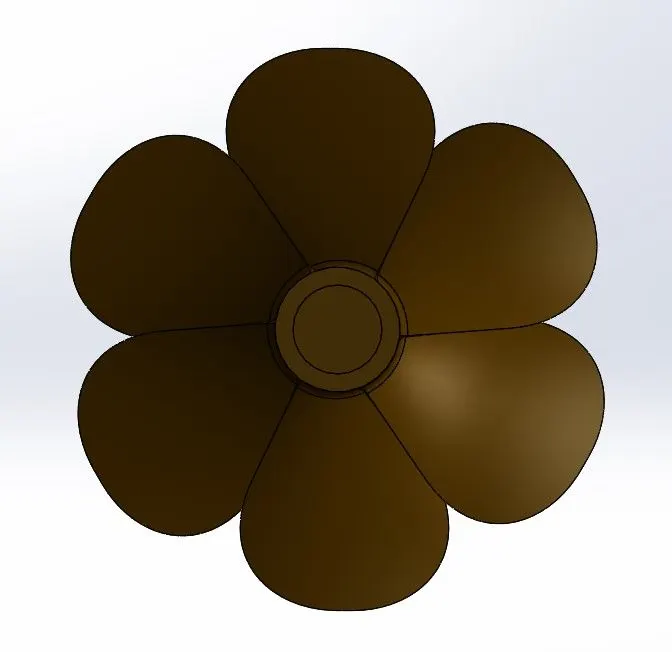
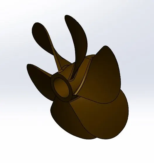
Radar:- A mandatory aid to navigation, the radar is used in identifying, tracking (with integrated ARPA) and positioning of vessels (including one’s own vessel) among other things in order to adhere to the COLREGs so as to safely navigate a ship from one point to another.
The marine radar is classified under the x-band (10 GHz) or S-band (3GHz) frequencies. The x-band, being of higher frequency is used for a sharper image and better resolution whereas the S-band is used especially when in rain or fog as well as for identification and tracking.
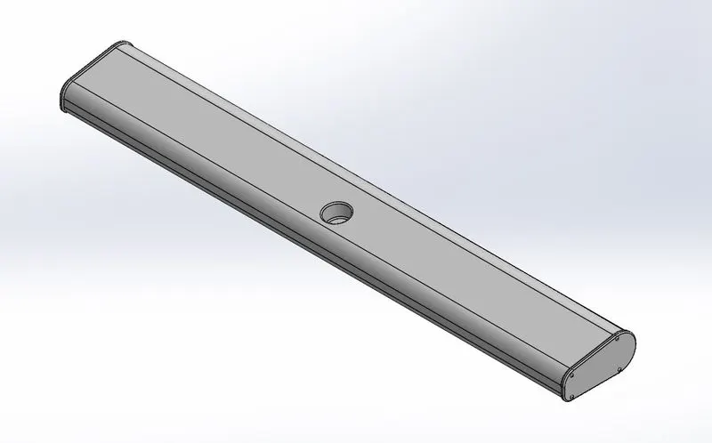
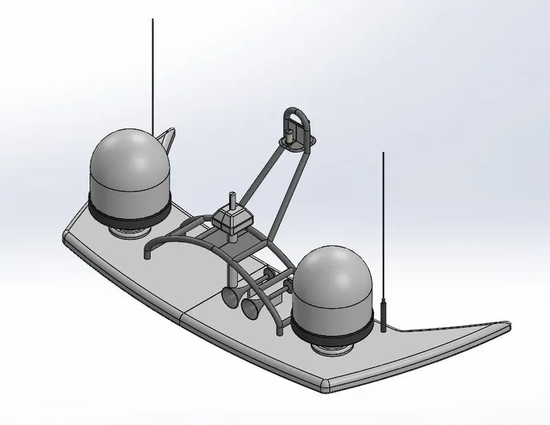
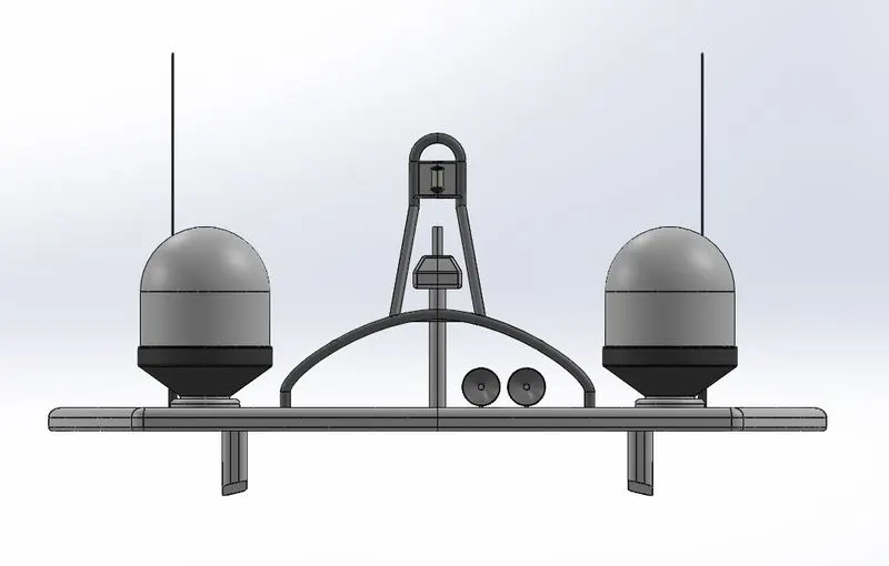
Radar Mast:-They are electronic navigation instruments that use a rotating antenna to sweep a narrow beam of microwaves around the water surface surrounding the ship to the horizon, detecting targets by microwaves reflected from them, generating a picture of the ship's surroundings on a display screen
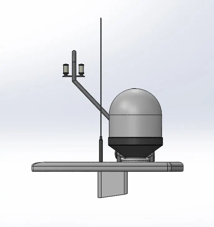
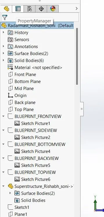
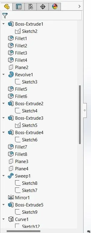
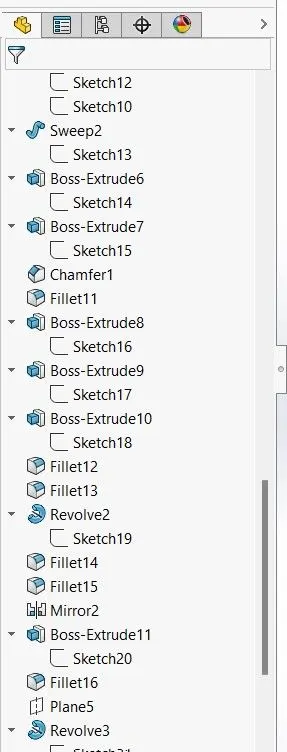
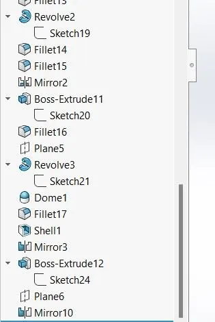
Hull:- The hull of a ship is the most notable structural entity of the ship. To define the hull, it can be said that it is the watertight enclosure of the ship, which protects the cargo, machinery, and accommodation spaces of the ship from the weather, flooding, and structural damage. But this alone does not suffice our requirements of understanding all the aspects of a ship’s hull.
In this article, we will see how the hull of a ship is designed for various factors taken into consideration during the entire lifetime of the ship, and how the design of a ship’s hull plays the most important role in the entire ship design and shipbuilding project.
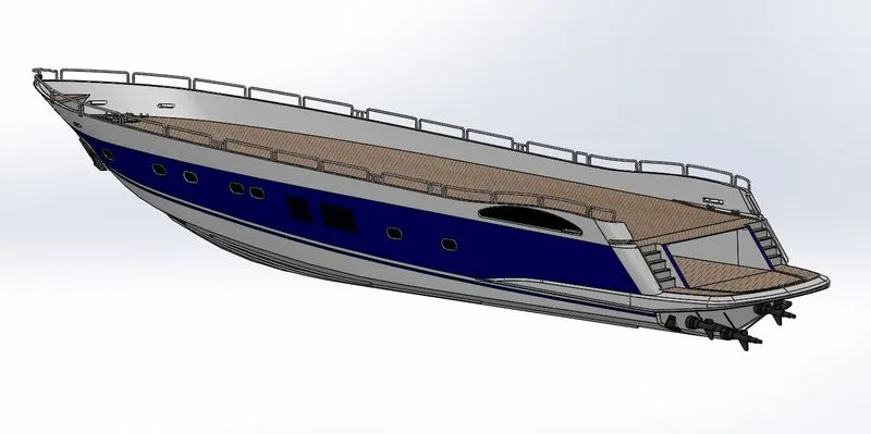
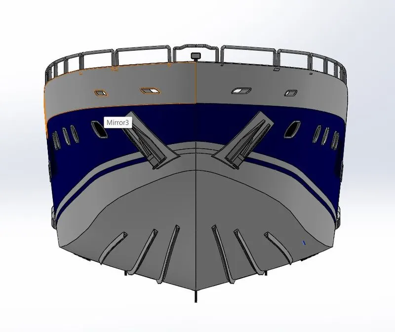
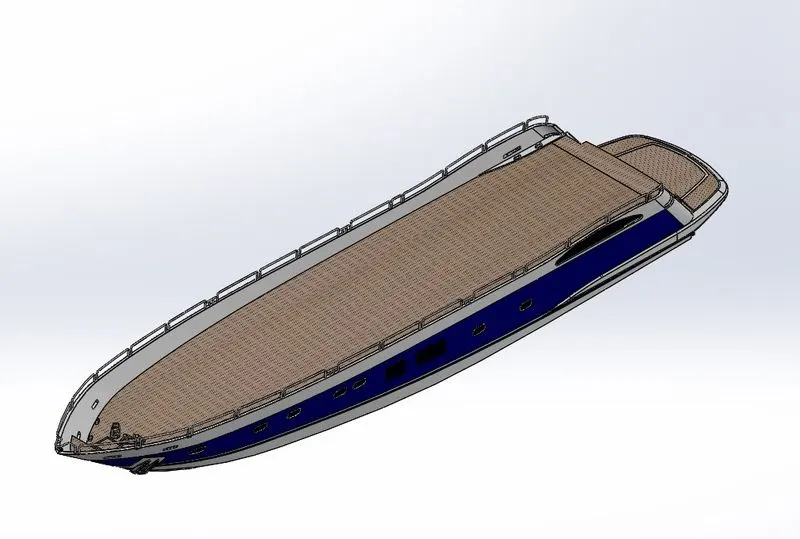
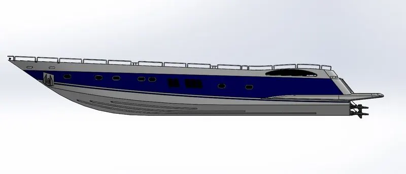
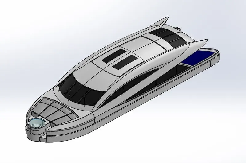
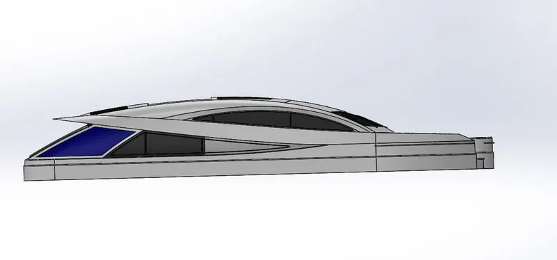
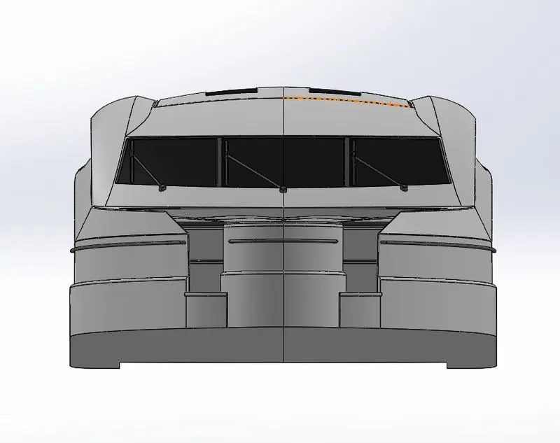
Superstructure:-A superstructure is an extended construction of any building or platform that rises above the rest of the building or platform in a distinct manner. The word comes from a combination of two Latin words, the Latin prefix ‘super’ means in addition or above or in excess of, whereas the stem word ‘structure’ means to build or to heap up. Thus, superstructure means to add a construction to an already existing structure. In ships this is the name given to the part of the ship that emerges from the deck. However any mast, sails, any armaments or arsenal are not included in this category.
The size of the superstructure has a great influence on the mobility of the vessels. They are designed in a manner, so that, they add value and hinder the speed and mobility in the least. The superstructure is mostly designed in fashion as well. This is because it is the most easily visible part of the ship, in fact it is the identification of the ship, and so the designers try to provide it with the identity that is unique.
Garage Door:-To assist the door's movement, the door is attached to a garage door opener by a curved arm. When prompted, the motor directs the movement of the door open or closed using the torsion spring system — or extension springs — to counterbalance the weight of the door, allowing safe and steady motion.
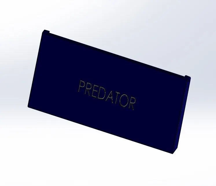
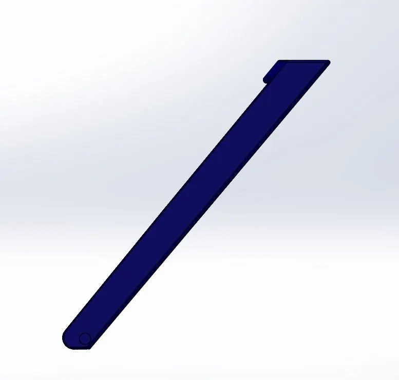
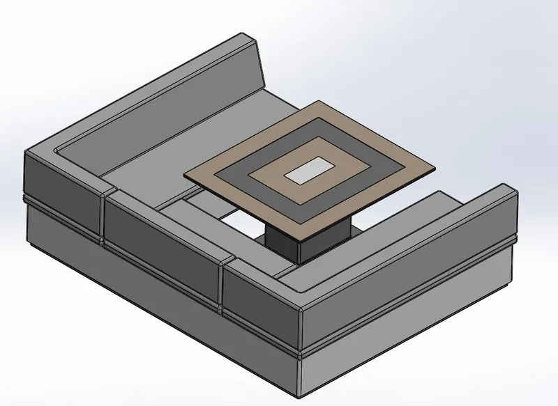
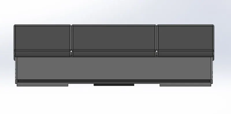
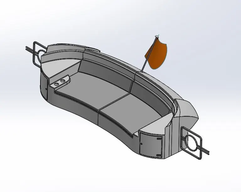
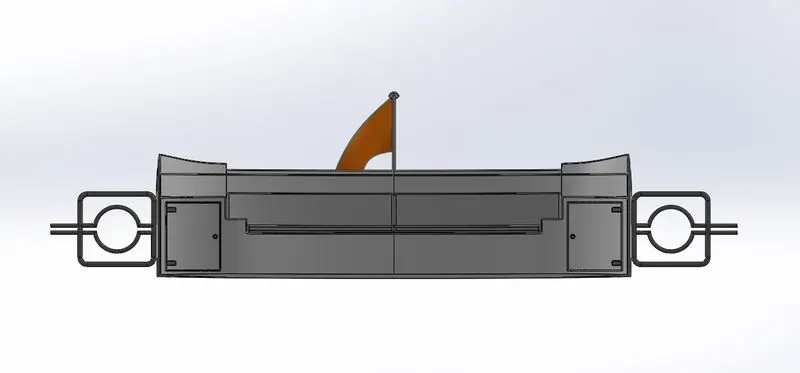
Front Seat, Rear Seat and Middle Seat:-Seats are modelled either by solid features or by using surface features. There are three seating in the model – Front, Middle and Rear.
Here, the Front and the Rear seats are modelled by first creating the outer surfaces using the features of the Surface tab. Then by creating a solid after carefully knitting the surfaces together using the Knit Surface feature.
1. Front Seat
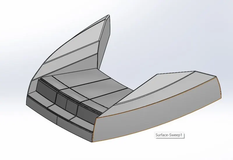
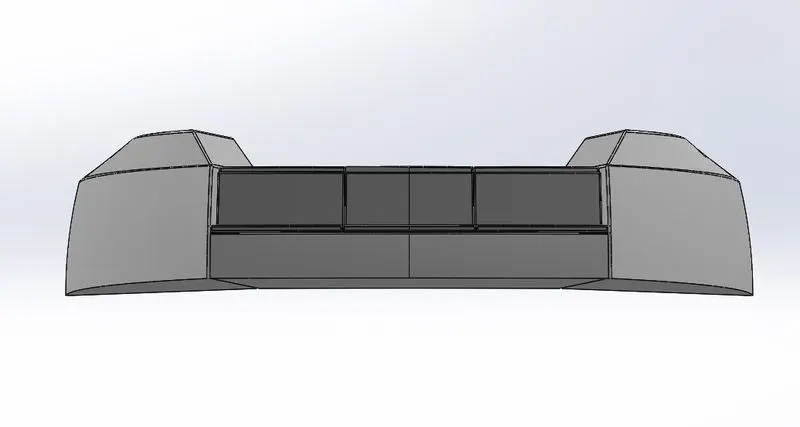
2.Middle Seat
3.Rear Seat
Final Assembly And Photo Realistic Rendering:-After all the parts are successfully modelled they are assembled in the assembly section interface of the SOLIDWORKS software, where all the components are assembled by applying appropriate constraints and mates between the structures and features. The following are the few snaps attached of the Yacht Assembly.
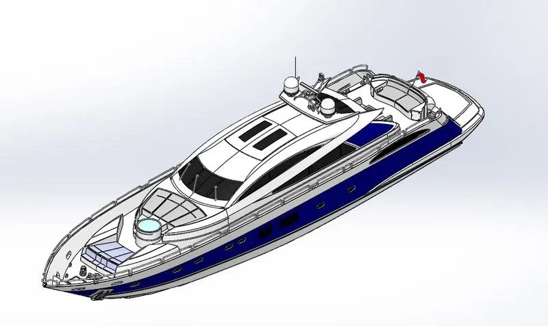
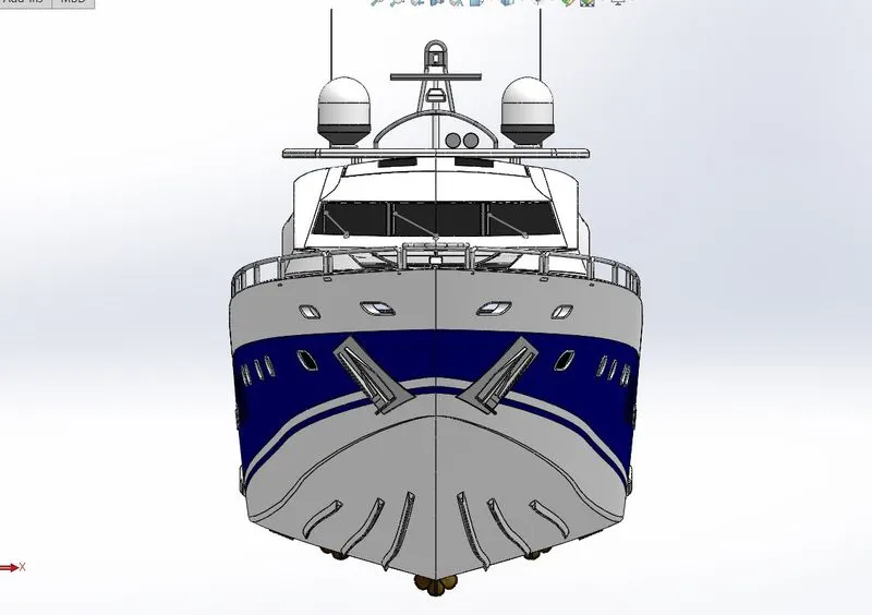
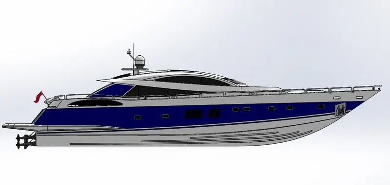
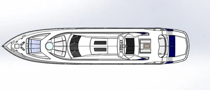
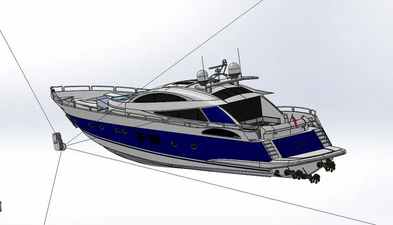
Photo Realistic Rendering:-After all the components are successfully assembled in the SOLIDWORKS software then the assembly is rendered with the various 3D realistic environment and the lights setup in finalised according to the environment used.The complete rendering process in done with the help of the SOLIDWORKS VISUALIZE software as it is one of the best tool available to create perfect realistic rendered images for the designed and modelled components.
Following rendered images of the Yacht are attached for the reference.
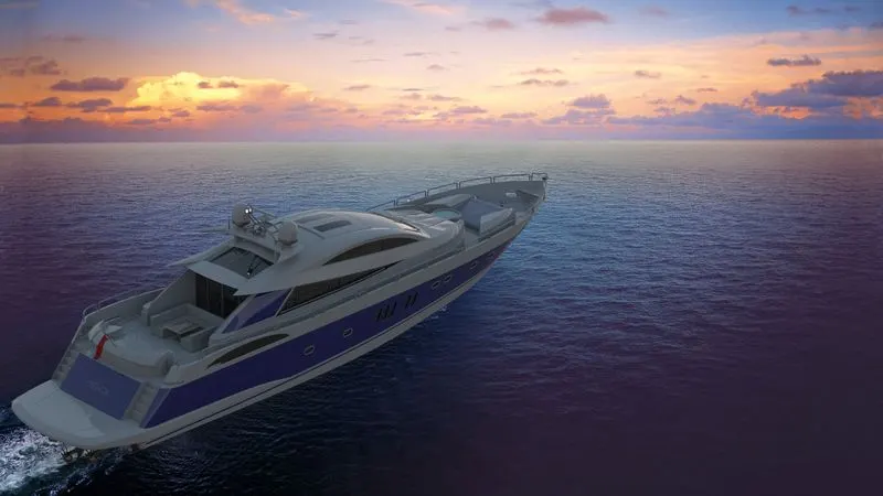
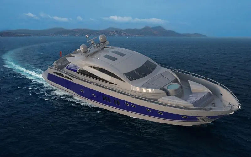
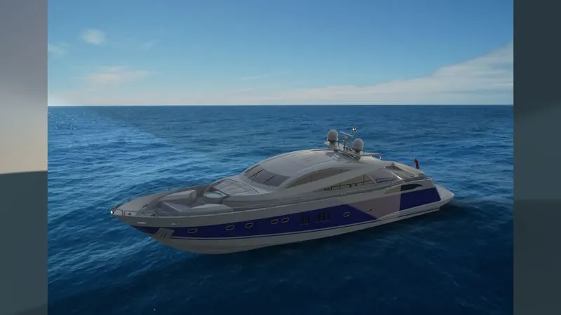
Conclusion:-Thus the Sunseeker Predator Yacht had been successfully modelled and assembled using SOLIDWORKS. Final Rendering is also carried out using and SOLIDWORKS VISUALIZE.